Wire Mode
Overview of Wire Mode
Wire Mode improves connectivity by allowing existing connections to fail over successfully by bypassing firewall enforcement. Traffic within a VPN community is, by definition, private and secure. In many cases, the firewall and the rule on the firewall concerning VPN connections is unnecessary. Using Wire Mode, the firewall can be bypassed for VPN connections by defining internal interfaces and communities as "trusted".
When a packet reaches a Security Gateway, the Security Gateway asks itself two questions regarding the packet(s):
Is this information coming from a "trusted" source?
Is this information going to a "trusted" destination?
If the answer to both questions is yes, and the VPN Community to which both Security Gateways belong is designated as "Wire Mode enabled," stateful inspection is not enforced and the traffic between the trusted interfaces bypasses the firewall. Since no stateful inspection takes place, no packets can be discarded. The VPN connection is no different from any other connection along a dedicated wire. This is the meaning of "Wire Mode." Since stateful inspection no longer takes place, dynamic routing protocols (which do not survive state verification in non-wire mode configuration) can now be deployed. Wire Mode thus facilitates Route Based VPN. For information on Route Based VPN, see Route Based VPN.
Wire Mode Scenarios
Wire mode can be used to improve connectivity and performance in different infrastructures. This section describes scenarios that benefit from the implementation of wire mode.
Wire Mode in a MEP Configuration
In this scenario:

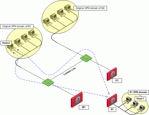
- Security Gateway M1 and Security Gateway M2 are both wire mode enabled and have trusted internal interfaces.
- The community where Security Gateway M1 and Security Gateway M2 reside, is wire mode enabled.
- Host 1, residing behind Security Gateway S1 is communicating through a VPN tunnel with Host 2 residing behind Security Gateway M1.
- MEP is configured for Security Gateway M1 and Security Gateway M2 with Security Gateway M1 being the primary Security Gateway and Security Gateway M2 as the backup. For more information on MEP see, Multiple Entry Point VPNs.
In this case, if Security Gateway M1 goes down, the connection fails over to Security Gateway M2. A packet leaving Host 2 will be redirected by the router behind Security Gateway M1 to Security Gateway M2 since Security Gateway M2 is designated as the backup Security Gateway. Without wire mode, stateful inspection is enforced at Security Gateway M2 and the connection is dropped. Packets that come into a Security Gateway whose session was initiated through a different Security Gateway, are considered "out-of-state" packets. Since Security Gateway M2's internal interface is "trusted," and wire mode in enabled on the community, no stateful inspection is performed and Security Gateway M2 will successfully continue the connection without losing any information.
Wire Mode with Route Based VPN
In this scenario:

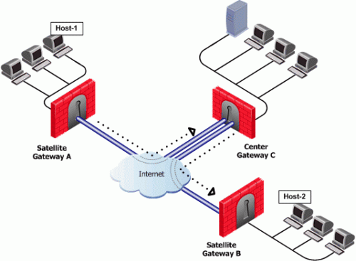
- Wire mode is enabled on Center Security Gateway C (without an internal trusted interface specified).
- The community is wire mode enabled.
- Host 1 residing behind Satellite Security Gateway A wishes to open a connection through a VPN tunnel with Host 2 behind Satellite Security Gateway B.
In a satellite community, Center Security Gateways are used to route traffic between Satellite Security Gateways within the community.
In this case, traffic from the Satellite Security Gateways is only rerouted by Security Gateway C and cannot pass through Security Gateway C's firewall. Therefore, stateful inspection does not need to take place at Security Gateway C. Since wire mode is enabled on the community and on Security Gateway C, making them trusted, stateful inspection is bypassed. Stateful inspection, however, does take place on Security Gateways A and B.
Wire Mode Between Two VPN Communities
In this scenario:

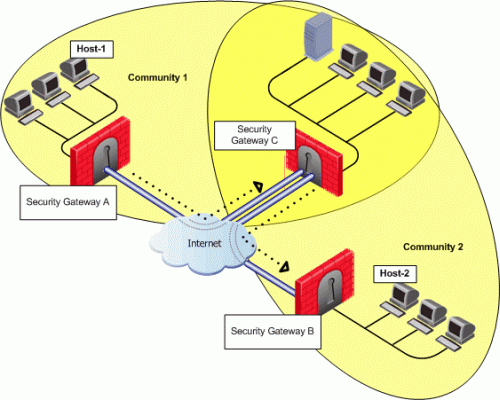
- Security Gateway A belongs to Community 1.
- Security Gateway B belongs to Community 2.
- Security Gateway C belongs to Communities 1 and 2.
- Wire mode is enabled on Center Security Gateway C (without an internal trusted interface specified).
- Wire mode is enabled on both communities.
- Host 1 residing behind Satellite Security Gateway A wishes to open a connection through a VPN tunnel with Host 2 behind Satellite Security Gateway B.
Wire mode can also be enabled for routing VPN traffic between two Security Gateways which are not members of the same community. Security Gateway C is a member of both communities and therefore recognizes both communities as trusted. When host 1 behind Security Gateway A initiates a connection to host 2 behind Security Gateway B, Security Gateway C is used to route traffic between the two communities. Since the traffic is not actually entering Security Gateway C, there is no need for stateful inspection to take place at that Security Gateway. Stateful inspection, however, does take place on Security Gateways A and B.
Special Considerations for Wire Mode
Wire mode is supported on SecurePlatform and Gaia platforms. It does not work with IPv6.
Configuring Wire Mode
Wire mode is configured in two places:
- Community Properties (meshed or star)
- Security Gateway Properties
Enabling Wire Mode on a VPN Community
- In SmartDashboard, click Manage > VPN Communities. The VPN Communities window appears.
- Select the community to be configured and click Edit.
- Double-click Advanced Settings to view the various options.
- Click Wire Mode.
The Wire Mode window opens.
- To enable Wire Mode on the community, select Allow uninspected encrypted traffic between Wire mode interfaces of the Community's members.
- To enable Wire Mode Routing, select Wire Mode Routing - Allow members to route uninspected encrypted traffic in VPN routing configurations.
Enabling Wire Mode on a Specific Security Gateway
- In SmartDashboard, click Manage > Network Objects. The Network Objects window will appear.
- Select the Security Gateway to be configured and click Edit.
- Double-click VPN to expand VPN tree. Select the VPN Advanced to display the VPN Advanced window.
- To enable Wire Mode on the Security Gateway, select Support Wire Mode.
- Click Add to include the interfaces to be trusted by the selected Security Gateway.
- Click Log Wire mode traffic to log wire mode activity.
|
|


