Installing Security Management Server and Security Gateways
Check Point software runs on many platforms and pre-configured appliances. Installations differ by deployment option, platform and operating system.
During installation, an automatic check is done to makes sure that there is enough disk space for the installation.
For more about supported deployments, platforms, hardware requirements and operating systems, see the R76 Release Notes.

|
Note - You must install, configure and activate the TCP/IP network protocol before you run the installation program.
|
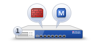
Installing Standalone
- The Security Management Server and the Security Gateway are installed on the same computer or appliance.
|
Item
|
Description
|
1
|
Standalone computer
|

|
Security Gateway component
|

|
Security Management Server component
|
Disk Partitions in a Gaia Clean Installation
In general, Gaia disk partitions in a clean installation are larger than SecurePlatform partitions.
On an appliance, the size of the disk partitions is predefined. During an installation you have 20 seconds to modify the predefined defaults. The non-interactive installation then continues.
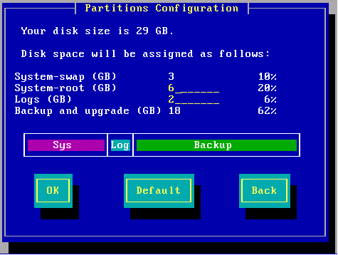
When installing Gaia on an open server, these partitions have default sizes:
- System-swap
- System-root
- Logs
- Backup and upgrade
You can change the System-root and the Logs partition sizes. The storage size assigned for backup and upgrade is updated accordingly.
For example:
To see the size of the system-root and log partitions on an installed system, enter expertdf -h
For example:
>df -h
Filesystem Size Used Avail Used% Mounted on
/dev/mapper/vg_splat-lv_current 13G 3.0G 9.0G 25% /
/dev/sda1 145M 19M 119M 14% /boot
tmpfs 187M 0 187M 0% /dev/shm
/dev/mapper/vg_splat-lv_log 9.0G 78M 2.7G 1% /var/log
|
In this example, the system root partition has 13G of disk space, and 9.0G is assigned for logs.
Most of the remaining space on the disk is reserved for backup images and upgrade. To see the disk space assigned for backup images, connect to the Gaia WebUI and go to the page. On an Open Server, the available space shown in the page is less than the space you defined when installing Gaia. The difference between the two amounts is the space reserved for upgrades. The amount of reserved space equals the size of the system-root partition.
Installing Standalone on Appliances
You can install a Standalone deployment on UTM-1 appliances, certain 2012 Models, and IP appliances. You can install the Gaia or SecurePlatform operating system. For more about supported appliances, see the R76 Release Notes.
UTM-1 and 2012 Models
In UTM-1 and 2012 model appliances, the first step to installation is to install the operating system.
Download the R76 ISO file for the relevant operating system and create a removable USB device, or burn it on a DVD disc. Use the ISO to do a clean install of SecurePlatform or Gaia on the appliance.
To install R76 SecurePlatform or Gaia:
- Download the ISO file with the R76 image for the Operating System: SecurePlatform or Gaia.
- Create a removable USB device (see sk65205) or burn the ISO file on a DVD.
- Turn off the appliance.
- Connect the installation media to the USB socket on the appliance.
If using a DVD, connect an external DVD drive and make sure that the DVD with the R76 ISO file is in the drive.
- Connect the supplied DB9 serial cable to the console port on the front of the appliance.
- Connect to the appliance using a terminal emulation program such as Microsoft HyperTerminal or PuTTY.
- Configure the terminal emulation program:
- In the HyperTerminalwindow, select a port from the list.
- In PuTTY select the connection type.
- Define the serial port settings: 9600 BPS, 8 bits, no parity, 1 stop bit.
- From the list, select .
- Connect to the appliance.
- Turn on the appliance.
The appliance begins the boot process and status messages show in the terminal emulation program.
- Press . You must press the Enter key within 90 seconds or the appliance boots from the hard drive.
The R76 ISO file is installed on the appliance.
- Reboot the appliance.
- For Gaia - Press .
- For SecurePlatform - Turn off the appliance and then turn it on again.
When the model number is shown on the LCD screen, the installation process is complete.
Gaia
To install Check Point products on Gaia UTM-1 and 2012 model appliances, use the First Time Configuration Wizard.
|
Note - The internal interface (INT) on a UTM-1 appliance is used as the management interface.
|
To start the First Time Configuration Wizard:
- Connect a standard network cable to the appliance management interface and to your management network.
The management interface is marked . This interface is preconfigured with the IP address 192.168.1.1
- Connect to the management interface from a computer on the same network subnet.
For example: IP address 192.168.1.x255.255.255.0
- To access the management interface, open a connection from a browser to the default management IP address:
https://192.168.1.1 - The login page opens. Log in to the system using the default username and password:
admin admin - Click .
|
Note - The features configured in the First Time Configuration Wizard are accessible after completing the wizard using the WebUI menu. The WebUI menu can be accessed by navigating to https://<appliance_ip_address>
|
- The runs.
To configure Gaia standalone appliances:
- In the First Time Configuration Wizard, set the password for and then click .
- Set the date and time manually, or enter the hostname, IPv4 address or IPv6 address of the NTP server and then click .
- Set the for the appliance.
- Optional: Set the , and IPv4 or IPv6 addresses for the .
Click .
- Set an IPv4 and an IPv6 address for the management interface, or set one IP address (IPv4 or IPv6).
If you change the management IP address, the new IP address is assigned to the interface. The old IP address is added as an alias and is used to maintain connectivity.
- Select and and then click .
- Set the username and password for the Security Management server administrator account and then click .
- Define the GUI Clients that can log in to the Security Management server. If you choose or , define an IPv4 or an IPv6 address. Click
- Click and then click OK.
- If the window shows, click or as necessary.
Gaia R76 is installed on the appliance.
- If necessary, download SmartConsole from the Gaia WebUI.
- Open a connection from a browser to the WebUI at
https://<management_ip_address> - In the page, click .
SecurePlatform
Use the SecurePlatform First Time Configuration Wizard to configure the new image on the appliance.
|
Note - The internal interface (INT) on a UTM-1 appliance is used as the management interface.
|
To start the First Time Configuration Wizard:
- Connect a standard network cable to the appliance management interface and to your management network.
The management interface is marked .
- Open Internet Explorer to the default management IP address,
https://192.168.1.1:4434 - Log in to the system using the default login name/password: .
|
Note - You can use the WebUI menu to configure the appliance settings. Navigate to https://<appliance_ip_address>:4434
|
- Set the username and password for the administrator account.
- Click .
The First Time Configuration Wizard opens.
To configure SecurePlatform standalone:
- In the First Time Configuration Wizard, set the date and time and then click .
- Configure the settings for the management and other interfaces and then click .
- Configure the settings for the routing table and then click .
- Set the , , and and then click .
- Select and then click .
- Do not configure the appliance as part of a cluster and then click .
- Set the clients that can manage the appliance using a web or SSH connection and then click .
- Download SmartConsole and then click .
The window shows the settings for the appliance.
- Click .
SecurePlatform R76 is installed on the appliance.
IP Appliances
For the IP Appliance models that are supported for this release, see the R76 Release Notes.
Gaia
You can install the Gaia operating system and Check Point Standalone, Security Management server, and Security Gateway deployments on IP appliances.
This section tells you how to do a clean installation of R76 Gaia on an IPSO platform in a Standalone deployment.
IPSO and Check Point product configurations are not imported. To keep your IPSO configuration, see the instructions for upgrading an IPSO Security Gateway IP appliance from IPSO to Gaia.
|
Note - You cannot upgrade an IPSO Standalone or Security Management server appliance to Gaia.
|
You can install R76 on all IP appliance platforms (IP150, IP280, IP290, IP390, IP560, IP690, IP1280, IP2450) using FTP over a network connection. You can also install R76 on all of these IP Appliance platforms except IP390 and IP560 using a USB removable device and the Check Point ISOmorphic utility.
- To install using a removable device see sk83200.
- To install over the network using FTP, continue with these instructions.
Preparing for Installation
Set up this environment.

Item
|
|
1
|
IP Appliance with
- IPSO
- IPSO to Gaia installation package or upgrade package.
|
2
|
FTP Server with a Gaia ISO image mounted. The ISO is copied to the IP Appliance as part of the installation or upgrade process. The FTP server can be Linux-based or Windows-based.
In this example, the FTP Server is at 192.0.2.2.
|
3
|
Optional: FTP Server used as a location for one or more of the following:
- Backup of IPSO and the Security Gateway configuration. (recommended)
- A special SmartUpdate package that can be to distribute the IPSO to Gaia installation and upgrade package to multiple Security Gateways.
- A special package that can be used to install or upgrade Security Gateways, one at a time, without having to answer any questions. This package is created using the answers supplied when running the installation and upgrade package.
You can use the same FTP server as for the Gaia ISO, or a different one. In this example, the FTP Server is at 192.0.2.3.
|
4
|
Computer with console access to the IP appliance and to the FTP server(s).
Console access is recommended because it allows you to keep the connection to the IP Appliance throughout the installation or upgrade. If you connect via SSH you lose the connection after the IP Appliance reboots, and you will not be able to track the installation or upgrade progress.
|
Installation Procedure Overview
|
|
|

|
Important - This is an overview of the steps, not the actual instructions. Detailed instructions follow.
|
Step 1: Get the IPSO to Gaia installation and upgrade package (tgz) and the Gaia ISO image.
Step 2: Put the Gaia ISO on an FTP server.
Step 3: Install the installation and upgrade package on the IP Appliance using Network Voyager or clish
Step 4: Run the script:
- Route to the FTP server
- Interface speed and duplex settings
- FTP access with the given credentials
- FTP access to the specified path
- Path contains the Gaia ISO and the user has Read/Write access to the directory
- Multiple simultaneous connections (>20) to the FTP server are allowed
- Timeout on FTP server is not too low
- FTP access to files downloaded by the Gaia boot manager
Step 6: Optional, but recommended: Enter data for an FTP server to hold IPSO system and configuration backup.
Step 7: Optional: Enter data to make a customized IPSO to Gaia upgrade package. Use this to upgrade multiple Security Gateways with SmartUpdate.
- Upgrade one Security Gateway with the standard IPSO to Gaia upgrade package. Enter the required data to create the special upgrade package.
- Upgrade all other Security Gateways simultaneously, using the special upgrade package, without more data. All IP Appliances must be able to access the same ftp servers as the first Security Gateway.
Step 8: Confirm your selections.
Step 9: The installation or upgrade package now runs automatically:
- If you made a backup package: The backup tar files are copied from the IP Appliance to the FTP server.
- If you made a customized installation or upgrade package: The package is copied from the IP Appliance to the FTP server.
- The Gaia image is copied from the FTP server to the IP Appliance.
- The Gaia image is installed.
- The Gaia boot manager is installed.
- The IP Appliance reboots.
You see the Gaia prompt on the IP Appliance.
|
Step 10: Run the First Time Configuration Wizard and select the products to install.
|
Step 1: Getting the Upgrade Package and the Gaia Image
- Download the Gaia packages for IP Appliance from the R76 home page on the Check Point Support Center.
You will see two packages:
- Gaia ISO image
- IPSO to Gaia installation and upgrade package. The file name is
Check_Point_Install_and_Upgrade_IPSO6.2_to_Gaia_R76.tgz
- Prepare the installation and upgrade packages:
Copy the packages to an FTP server, in a directory of your choice. Or transfer the packages by FTP to the IP Appliance.
Step 2: Putting the Gaia ISO on an FTP Server
Network Requirements
|
Important - High network traffic or large transfers (more than 10/100 Mbps links) can interfere with the FTP transfers for installation.
|
- Make sure the appliance can reach the FTP server.
- Make sure there is no Firewall which blocks incoming FTP requests from the appliance to the FTP server.
- Configure the FTP server to allow more than 100 (or an unlimited number of) concurrent connections.
- Make sure the Gaia ISO file is mounted on a directory to which the user has access permissions.
On a Linux-based FTP Server:
- Upload the Gaia ISO file to the FTP server
- On the FTP server, run:
mount -o loop -t iso9660 <ISO_filename> <mounting_destination_dir>
On a Windows-based FTP Server:
- Upload the Gaia ISO file to the FTP server
- Extract the Gaia ISO file to a folder on the FTP Server. Use 7-zip, Winzip, WinRAR or similar.
- In the folder, run the file
copyrpms.batThis batch file copies installation files, to give a required workaround to Windows' inability to support soft links.
- Give FTP credentials to the folder, so the folder can be accessed via FTP.
|
Step 3: Installing the Package on the IP Appliance
- Log in to the IP Appliance using a console.
- Run
clish - Install the IPSO to Gaia installation and upgrade package on the IPSO appliance using
clish
To use clishNote - If using anonymous ftp, change ftp anonftp
The installation and upgrade package is installed.
Trying to install package: ./.tgz
Package Information --
Name : IPSO to Gaia Upgrade
Version : <version>
Release : <Release>
Description: IPSO to Gaia Upgrade Package (<package_version>)
Package will be installed under: /opt
Package installed and activated successfully.
End of package installation.
|
The installation success message is Package installed and activated successfully
The package is reported to be activated, but there are no background processes running.
- Show the installed and active packages:
show package active
Name Ver Rel Dir Desc
{Check Point CPinfo } 10 00 /opt/CPinfo-10 {Check Point CPinfo}
{Check Point R70} R70 00 /opt/CPsuite-R70 {Check Point R70}
{IPSO to Gaia Upgrade} <ver> <rel> /opt/<package_name> {IPSO to Gaia Upgrade Package (<upgrade_package_version>)}
|
- Exit clish. Run:
exit
Step 4: Running the Installation and Upgrade Script
- Go to the location of the package
cd /opt/<package_name>/
- To upgrade, run
./run-upgrade-to-Gaia To do a clean installation, run
./run-install-Gaia
If you are upgrading multiple appliances from a special upgrade package that was previously saved, the installation or upgrade runs automatically. Continue with Step 9.
If you are upgrading or installing one appliance, continue here.
The script runs. The following shows an upgrade. If you do a clean installation, the IPSO configuration is not transferred to Gaia.
Welcome to the IPSO to Gaia Install/Upgrade procedure.
Checking platform...OK
Checking IPSO OS version ...OK
Checking hostname ...
Checking your configuration
Summary:
Errors: 0
Warnings: 0
Information: 14
Total Grade: 94
Details in file "/var/tmp/verify-IPSO-for-Gaia.msgs".
A newer version of this script may be available.
Contact the Check Point UserCenter at https://usercenter.checkpoint.com
and see SK66569.
Do you want to continue with the upgrade ? [y] y
=========================================================
The following types of information are needed to prepare
your IPSO appliance for the upgrade:
- info about downloading the Gaia image.
- info about transferring the verification reports (optional).
- info about transferring an IPSO backup (optional).
- info about transferring a special upgrade package with your answers (optional).
Answer the prompts for this info and then the upgrade is performed.
Hit 'Enter' to continue or Ctrl-C to exit
|
- Supply the information for downloading the Gaia image
|
Note - If you have run the upgrade script before, the previously entered values are shown in square brackets [ ]. Press Enter to accept the values, or type in the new values and press Enter.
|
Step 5: Verifying the FTP Server
Enter the requested FTP server data and the path to the Gaia installation file.
|
Required Directory Value
|
If ISO is mounted to a non-FTP directory
|
Enter full path to ISO.
A relative path or shortcut link will not work.
Example: if , ./gaia
|
If ISO is mounted to , and FTP user account is used to install
|
Enter path to ISO. A shortened path will work.
Example: if , gaia
|
If ISO is mounted to , and non-FTP user account is used to install
|
Enter full path to ISO.
A relative path or shortcut link will not work.
|
The script runs some tests to verify the FTP environment. If errors are detected, correct the FTP server configuration and then instruct the program to verify the FTP environment again.
Here is an example of a successful test:
Info for download of the Gaia image:
Info for download of the Gaia image:
IP address of FTP server [192.0.2.2]:
User name [gwhite]:
Password [******]:
Directory [/mnt/fiber292]:
Performing tests of access to FTP server and Gaia ISO
Checking route to 192.0.2.2 ... OK
Interface: eth-s4p1 speed 100M, duplex full
Checking FTP access with given credentials ... OK
Checking FTP access to /mnt/fiber292 ... OK
Checking /mnt/fiber292 is Gaia ISO ... Yes
Checking multiple simultaneous connections to 192.0.2.2 ... OK
Checking timeout to 192.0.2.2 ... OK
Checking FTP access to files downloaded by Gaia boot-manager
system/ramdisk.pxe ... OK
system/base/stage2.img ... OK
|
Step 6 (Optional, Recommended): Supplying Reports and Backup Server Information
The script will request details of the FTP server to store reports and backup data. The same path-rules apply here as in Step 5. The backup creates two tgz files, for:
- IPSO operating system configuration files, user directories, and log files.
- Security Gateway backup files.
Here is an example:
A complete backup of the IPSO system can performed
including system configuration, user home directories,
log files and files from packages.
Do you want to perform this backup ? [y]
Use IP address '192.0.2.2' and user 'root' for the backup? [n]
Details for transferring the IPSO Backup:
IP address of FTP server []: 192.0.2.3
User name []: ftp
Password []: ***
Directory []: /backupdir
Checking FTP access to 192.0.2.3 (it may take a minute) ... done
|
Step 7: (Optional): Supplying Special Package Server Information
Enter data of the destination FTP server for the special upgrade package. Enter a destination directory, with the same rules as in Step 5.
A package with your answers to the previous prompts can be created.
This package can be used on other IPSO gateways for
unattended conversion to Gaia.
Do you want to create such a package? [y]
Details for transferring the package with your answers:
IP address of FTP server [192.0.2.3]:
User name [ftp]:
Password [***]:
Directory [packagedir]:
Checking FTP access to 192.0.2.3 (it may take a minute) ... done
|
Step 8: Confirming Your Selections
You see a summary of all your answers.
Information for download of the Gaia image:
FTP Server IP Address = 192.0.2.2
FTP Server user name = root
Directory on FTP Server = /imagedir
Information for transferring the IPSO Backup:
FTP Server IP Address = 192.0.2.3
FTP Server user name = ftp
Directory on FTP Server = /backupdir
Information for transferring the package with your answers:
FTP Server IP Address = 192.0.2.3
FTP Server user name = ftp
Directory on FTP Server = /packagedir
Are these values correct? [y]
|
- Click
nThe backup file and the special upgrade package file, if you chose to create them, are created.
Writing values to file
Performing IPSO backup (file <ipso_backup_file_name>.tgz) ... done
Performing Check Point Security Gateway backup (file <Security Gateway_backup_file_name>.tgz) ... done
Transferring IPSO and Check Point Security Gateway backup files ... done
Creating a package with your answers (<package_name>_AUTO.tgz) ... done
Transferring package with your answers ... done
Installing Gaia Boot Manager ... done
|
- You have 30 seconds to abort. To stop the upgrade, press .
IP appliance reboots in 30 seconds to complete the upgrade.
Hit 'Enter' to abort.
|
|
Important - If you want to make changes, press Enter now.
This stops the upgrade to Gaia. To complete the upgrade to Gaia, reboot the IP Appliance.
|
Step 9: Installation Runs Automatically
The installation runs unattended.
- The IP Appliance reboots.
- The Gaia Boot Manager runs.
|
Important - After reboot, the system sometimes shows the Boot Manager prompt.
To complete installation, type INSTALL
|
- The Gaia image is installed.
- The IPSO and R76 configurations are not imported into Gaia.
- The Gaia prompt shows.
|
Important - The HTTPS port for the WebUI is set to 443 after an installation or upgrade.
To change this, you must use SmartDashboard > > .
|
Step 10: Selecting Check Point Products
To configure Check Point products on Gaia, use the First Time Configuration Wizard. Configure the operating system and install the products in one wizard.
To configure standalone products on Gaia:
- Using your Web browser, go to the WebUI:
https://<Gaia management IP address>
- In the window, log in using the administrator name and password that you defined during the installation procedure.
- The WebUI shows the . Click .
- Set the date and time manually, or enter the hostname, IPv4 address or IPv6 address of the NTP server and then click .
- Set the for the appliance.
- Optional: Set the , and IPv4 or IPv6 addresses for the .
Click .
- Set an IPv4 and an IPv6 address for the management interface, or set one IP address (IPv4 or IPv6).
If you change the management IP address, the new IP address is assigned to the interface. The old IP address is added as an alias and is used to maintain connectivity.
- Set the username and password for the Security Management server administrator account and then click .
- Select and and then click .
- Define the GUI Clients that can log in to the Security Management server. If you choose or , define an IPv4 or an IPv6 address. Click
- Click and then click OK.
- If the window shows, click or as necessary.
After some minutes, you can use the WebUI to configure your standalone environment.
Rollback from Gaia to IPSO
You can roll back from Gaia to IPSO 6.2. You can also restore the Check Point Security Gateway and/or Security Management server configuration.
Before doing a rollback from Gaia to IPSO:
Make sure that:
- The IPSO boot manager installer is available. Download it from the R76 home page.
- An IPSO image is available. Put the IPSO image on an FTP server, and make sure that the FTP server is accessible from the Gaia IP Appliance.
- A backup of the Check Point Security Gateway on the Gaia IP Appliance is available. Put the backup tar file on an FTP server, and make sure the FTP server is accessible from the Gaia IP Appliance.
To roll back from Gaia to IPSO:
- At the Gaia command line prompt, login as the administrator.
- Go to expert mode. Type
expert. - Download the IPSO boot manager installer
Check_Point_R76_Install_IPSOBootmanager.sh - Copy the IPSO boot manager installer to a location of your choice on the Gaia IP Appliance. For example, to
/var/tmp - Change file attributes to give executable permissions. Run
chmod 777 Check_Point_R76_Install_IPSOBootmanager.sh
- Install the IPSO boot manager. At the command prompt run
./Check_Point_R76_Install_IPSOBootmanager.sh /dev/hda
The script asks if you want to roll back to
1. IPSO 4.2
2. IPSO 6.2
- Choose
2 - Type
rebootAfter the reboot, the system is running the IPSO boot manager.
- At the
BOOTMGR>install
- Enter this data:
- IP address of the IP Appliance.
- Default gateway of the IP Appliance.
- IP address of the FTP server with the IPSO image.
- User credentials.
- Directory path.
- Various configuration questions (about the chassis serial number, whether the system is part of a VRRP cluster, and whether IGMP and BGP are enabled).
The system automatically reboots into IPSO.
- Configure the IP Appliance:
- Hostname
- New password for
admin - Enable the management port physical interface
- IP address for the management interface
- Default gateway
To restore the Check Point Security Gateway configuration:
- Log in to the newly installed and configured IPSO IP Appliance as
admin - Use FTP to transfer the backup archive file containing the Check Point Security Gateway to the IP Appliance, and then uncompress the archive. In the following example,
- The name of the backup archive is
CP_archive_nms71_20101124.tgz - The IP address of the FTP server containing the backup archive is 192.0.2.3.
cd /tmp
ftp ftp://192.0.2.3>/pub/CP_archive_nms71_20101124.tgz
tar xzf /tmp/CP_archive_nms71_20101124.tgz
|
- Restore the IPSO backup file using the
set restore- The IP address of the FTP server containing the IPSO backup file is 192.0.2.2
- The IPSO backup file is in the
pub
|
|
|
|
Important - If the backup contains IPSO and Check Point configuration data, the Check Point packages must be installed first before trying to restore the backup; otherwise the restore will fail.
|
clish
set restore remote ftp-site ftp://192.0.2.2
set restore remote ftp-user <username e.g. anonymous>
set restore remote ftp-pass <password>
set restore remote ftp-dir pub
set restore remote filename i2g_backup_<hostname and timestamp>.tgz
|
IPSO automatically reboots.
- Log out.
- Log in as
admin - Verify the configuration has been restored.
IPSO
For IPSO requirements see the R76 Release Notes.
To install on IPSO:
- Install IPSO 6.2 MR4. See the IPSO 6.2 MR4 Release Notes.
- Install R76 for IPSO.
Installing Standalone on Open Servers
A standalone deployment can be installed on any computer that meets the minimum requirements (see the Release Notes). For Gaia and SecurePlatform, first install and configure the operating system. Then install Check Point products. You can also install on Windows.
Gaia
This procedure explains how to install the Gaia operating system on an open server. Then you configure the Standalone Check Point products.
To install Gaia on an open server:
- Start the computer using the installation media.
- When the first screen shows, select and press
- You must press in 60 seconds, or the computer will try to start from the hard drive. The timer countdown stops once you press . There is no time limit for the subsequent steps.
- Press to continue with the installation.
- Select a keyboard language. English US is the default.
- Make sure the disk space allocation is appropriate for the environment.
- Enter and confirm the password for the account.
- Select the management interface (default =
eth0 - Configure the management IP address, net mask and default gateway. You can define the DHCP server on this interface.
- Select to format your hard drive and start the installation.
- Press to complete the installation.
To configure Check Point products on Gaia, use the First Time Configuration Wizard. Configure the operating system and install the products in one wizard.
To configure standalone products on Gaia:
- Using your Web browser, go to the WebUI:
https://<Gaia management IP address>
- In the window, log in using the administrator name and password that you defined during the installation procedure.
- The WebUI shows the . Click .
- Set the date and time manually, or enter the hostname, IPv4 address or IPv6 address of the NTP server and then click .
- Set the for the appliance.
- Optional: Set the , and IPv4 or IPv6 addresses for the .
Click .
- Set an IPv4 and an IPv6 address for the management interface, or set one IP address (IPv4 or IPv6).
If you change the management IP address, the new IP address is assigned to the interface. The old IP address is added as an alias and is used to maintain connectivity.
- Set the username and password for the Security Management server administrator account and then click .
- Select and and then click .
- Define the GUI Clients that can log in to the Security Management server. If you choose or , define an IPv4 or an IPv6 address. Click
- Click and then click OK.
- If the window shows, click or as necessary.
After some minutes, you can use the WebUI to configure your standalone environment.
- If necessary, download SmartConsole from the Gaia WebUI.
- Open a connection from a browser to the WebUI at
https://<management_ip_address> - In the page, click .
To configure a Gaia Secondary Security Management server on a Standalone Open Server:
Use the same procedure as for the primary Security Management server, with these changes:
- In the First Time Configuration Wizard, use a different IP address for the management interface. Make sure that the primary and secondary Security Management servers are on the same subnet.
- In the page, as Secondary.
- In the , define the Use this key to configure the secondary Security Management Server object in SmartDashboard.
SecurePlatform
|
Important - Installing the SecurePlatform operating system deletes all data on the hard drive.
|
To install on SecurePlatform using removable media:
- Put the installation removable media into the drive and boot the computer from the removable media.
- When the SecurePlatform window opens, press Enter.
You must press Enter in 90 seconds, or the computer starts from the hard drive.
- If error messages show during the hardware compatibility scan, correct the problems and then restart the procedure from step 1.
- Optional: Click to resolve hardware compatibility issues.
- Click to continue with the installation.
- Select a keyboard language and then click OK.
- Select as the management interface (networking device) and then click .
- Configure the settings for the interface (NIC) and then click .
- Not for Multi-Domain Server: Configure the clients that can connect to the WebUI and then click OK.
|
Note - If you are going to deploy remote access or Endpoint Security software, do not use the default port, 443
|
- Click to install SecurePlatform.
- When the window opens, disconnect the removable media from the computer.
- Click to complete the installation process and restart the computer.
When the computer restarts, configure the operating system. You can use the WebUI or using the CLI.
To configure SecurePlatform using the WebUI:
- Open a browser to the administration IP address:
- For appliances - https://<IP_address>:4434
- For open servers - https://<IP_address>
|
Note - Pop-ups must always be allowed on https://<IP_address>.
|
The login page appears.
- Login with the default login name () password () and click .
- Download the password recovery login token file. Save it in a safe place.
- Change the default login name and password.
- Click .
In the First Time Configuration Wizard, configure these settings:
- Network connections. The management interface has the administration IP address.
- Routing table.
- DNS servers.
- Host and domain name.
- Date, time, and time zone.
- Allowed IPs of SSH and administration WebUI clients.
- Products to install. For standalone, select and .
- Security Management Installation Type.
- Security Management GUI Clients.
- Security Management administrators.
- Click
To configure SecurePlatform using the CLI:
- Log in to the system using the default login name/password: .
- Set the username and password for the administrator account.
- Run:
sysconfigThe first-time system configuration wizard starts. Enter n to continue.
- Set the , , and .
- Configure the settings for the management and other interfaces (network connections).
- Configure the settings for the routing table and then enter .
- Set the date and time and then enter .
After you install and configure the SecurePlatform operating system on an open server, install the Check Point products for Security Management Server and Security Gateway.
When you complete this procedure, IP forwarding is automatically disabled on the Security Gateway. A default security policy is enforced. This policy blocks all inbound connections, except for control connections. This policy is used until you install a new security policy.
To install products on a standalone SecurePlatform computer using the CLI:
- To import a product configuration file from a TFTP server, enter 1 and do the on-screen instructions. Otherwise, enter n to continue.
- In the Welcome window, enter n to continue.
- Enter to accept the End User License agreement.
- Do one of these actions:
- New product installation - Select New Installation and then enter n.
- Use the imported installation file - Select Installation Using Imported Configuration and then enter n.
- Select the Check Point Security Gateway and Security Management server Software Blades to install, and enter n.
- Select Security Gateway and Security Management and enter n.
- SelectPrimary Security Management.
- In the Validation window, enter n.
- Enter n
- Optional: Enter y to save the certificate fingerprint to a file. Otherwise press n.
- Press Enter.
- Restart the computer.
To install a Secondary Security Management server on a SecurePlatform open server:
Use the same procedure as for the Primary Security Management server, with these changes:
- Use a different IP address for the management interface. Make sure that the primary and secondary appliances are on the same subnet.
- WebUI Configuration:
- In the First Time Configuration Wizard, in the page, select Secondary Security Management.
- In the Secure internal Communication page, define the Use this key to configure the secondary Security Management Server object in SmartDashboard.
- CLI Configuration:
- When installing Products after running
sysconfig - When prompted, define the Activation Key. Use this key to configure the secondary Security Management Server object in SmartDashboard.
Windows
You can do a clean installation of Check Point products on a Windows open server. If you have a configuration file from a supported upgrade path, you can import the configuration to the new R76 installation.
|
Note - If the required version of Microsoft.Net framework is not installed, it is installed during installation. This can take several minutes.
If necessary, the Windows Imaging Component is installed during installation.
|
To install on Windows:
- Log in to Windows using credentials.
- Put the installation media in the drive.
The installation wizard starts automatically.
Click .
- Accept the
Click .
- Select
Click .
- Select
Click .
- Select , and .
- Optional: Select .
Click .
- If prompted, confirm or change the destination folder
Click .
- Select Alternatively, in a Management High Availability deployment, to install the second Security Management server, select
Click .
- Review your selections
Click .
- Click .
- Restart the computer.
To install on Windows with a configuration file:
- In the first window after the License Agreement, select and click .
- Select the path of the imported configuration file and click .
- Select an option for obtaining the latest upgrade utilities and click .
- Continue with step 6 above.
Installing Security Management Server
- The Security Gateway and the Security Management Server are installed on different computers.
|
|
Item
|
Description
|
1
|
Security Management Server
|
2
|
Network connection
|
3
|
Security Gateway
|
|
Security Gateway component
|
|
Security Management Server component
|
This section explains how to install the Security Management Server.
Disk Partitions in a Gaia Clean Installation
In general, Gaia disk partitions in a clean installation are larger than SecurePlatform partitions.
On an appliance, the size of the disk partitions is predefined. During an installation you have 20 seconds to modify the predefined defaults. The non-interactive installation then continues.
When installing Gaia on an open server, these partitions have default sizes:
- System-swap
- System-root
- Logs
- Backup and upgrade
You can change the System-root and the Logs partition sizes. The storage size assigned for backup and upgrade is updated accordingly.
For example:
To see the size of the system-root and log partitions on an installed system, enter expertdf -h
For example:
>df -h
Filesystem Size Used Avail Used% Mounted on
/dev/mapper/vg_splat-lv_current 13G 3.0G 9.0G 25% /
/dev/sda1 145M 19M 119M 14% /boot
tmpfs 187M 0 187M 0% /dev/shm
/dev/mapper/vg_splat-lv_log 9.0G 78M 2.7G 1% /var/log
|
In this example, the system root partition has 13G of disk space, and 9.0G is assigned for logs.
Most of the remaining space on the disk is reserved for backup images and upgrade. To see the disk space assigned for backup images, connect to the Gaia WebUI and go to the page. On an Open Server, the available space shown in the page is less than the space you defined when installing Gaia. The difference between the two amounts is the space reserved for upgrades. The amount of reserved space equals the size of the system-root partition.
Installing Security Management Server on Appliances
You can install a Security Management server on Smart-1 appliances. The appliance platform can be Gaia or SecurePlatform. For more about supported appliances, see the R76 Release Notes.
Smart-1
- Make sure that you have the correct ISO file.
- Install the Gaia or SecurePlatform operating system on Smart-1. See instructions in UTM-1 and 2012 Models.
- Smart-1 50 only: Smart-1 50 appliances have two images: Security Management server and Multi-Domain Server. To select the Security Management server image:
- While the appliance is restarting, open the terminal emulation program.
- When prompted, press any key to enter the boot menu.
- Select and press .
- Type and press .
The Security Management server image is selected for the appliance and then the appliance resets.
- Install the Security Management server using the First Time Configuration Wizard.
Gaia
To install the Security Management Server on Smart-1, use the First Time Configuration Wizard.
To start the First Time Configuration Wizard:
- Connect a standard network cable to the appliance management interface and to your management network.
The management interface is marked . This interface is preconfigured with the IP address 192.168.1.1
- Connect to the management interface from a computer on the same network subnet.
For example: IP address 192.168.1.x255.255.255.0
- To access the management interface, open a connection from a browser to the default management IP address:
https://192.168.1.1 - The login page opens. Log in to the system using the default username and password:
admin admin - Click .
|
Note - The features configured in the First Time Configuration Wizard are accessible after completing the wizard using the WebUI menu. The WebUI menu can be accessed by navigating to https://<appliance_ip_address>
|
- The runs.
To configure Gaia Security Management on appliances:
- In the First Time Configuration Wizard, set the password for the administrator account and then click .
- Set the date and time manually, or enter the hostname, IPv4 address or IPv6 address of the NTP server and then click .
- Set the for the appliance.
- Optional: Set the , and IPv4 or IPv6 addresses for the .
Click .
- Set an IPv4 and an IPv6 address for the management interface, or set one IP address (IPv4 or IPv6).
If you change the management IP address, the new IP address is assigned to the interface. The old IP address is added as an alias and is used to maintain connectivity.
- For the appliance type, select .
Click .
- In the section, select and
Click .
- Set the username and password for the Security Management server administrator account for SmartConsole clients and then click .
- Define the GUI Clients that can log in to the Security Management server. If you choose or , define an IPv4 or an IPv6 address. Click
- Click and then click OK.
- If the window shows, click or as necessary.
Gaia R76 is installed on the appliance.
- If necessary, download SmartConsole from the Gaia WebUI.
- Open a connection from a browser to the WebUI at
https://<management_ip_address> - In the page, click .
To configure a Gaia secondary Security Management on Smart-1:
Use the same procedure as for the primary Security Management server, with these changes:
- In the First Time Configuration Wizard, use a different IP address for the management interface. Make sure that the primary and secondary Security Management servers are on the same subnet.
- In the page, as Secondary.
- In the , define the Use this key to configure the secondary Security Management Server object in SmartDashboard.
SecurePlatform
To install the Security Management Server on Smart-1 appliances, use the First Time Configuration Wizard.
To start the First Time Configuration Wizard:
- Connect a standard network cable to the appliance management interface and to your management network.
The management interface is marked .
- Open Internet Explorer to the default management IP address,
https://192.168.1.1:4434 - Log in to the system using the default login name/password: .
|
Note - You can use the WebUI menu to configure the appliance settings. Navigate to https://<appliance_ip_address>:4434
|
- Set the username and password for the administrator account.
- Click .
The First Time Configuration Wizard opens.
To configure a SecurePlatform Security Management:
- In the First Time Configuration Wizard, set the date and time and then click .
- Configure the settings for the management and other interfaces and then click .
- Configure the settings for the routing table and then click .
- Set the , , and and then click .
- For Security Management installation type, select and then click .
- Set the clients that can manage the appliance using a web or SSH connection and then click .
- Download SmartConsole and then click .
The window shows the settings for the appliance.
- Click .
SecurePlatform R76 is installed on the appliance.
To configure a SecurePlatform Secondary Security Management on Smart-1:
Use the same procedure as for the Primary Security Management server, with these changes:
- Use a different IP address for the management interface. Make sure that the primary and secondary appliances are on the same subnet.
- In the First Time Configuration Wizard, in the page, select Secondary Security Management.
- In the Secure internal Communication page, define the Use this key to configure the secondary Security Management Server object in SmartDashboard.
Installing Security Management Server on Open Servers
A Security Management server can be installed on any computer that meets the minimum requirements (see the Release Notes). For Gaia and SecurePlatform, first install and configure the operating system. Then install Check Point products. You can also install on Windows.
Gaia
This procedure explains how to install a Security Management Server in a distributed deployment after you install the operating system.
To configure a Security Management Server on Gaia:
- Using your Web browser, go the WebUI:
https://<Gaia management IP address>
- In the window, log in using the administrator name and password that you defined during the installation procedure.
- The WebUI shows the . Click .
- Set the date and time manually, or enter the hostname, IPv4 address or IPv6 address of the NTP server and then click .
- Set the for the appliance.
- Optional: Set the , and IPv4 or IPv6 addresses for the .
Click .
- Set an IPv4 and an IPv6 address for the management interface, or set one IP address (IPv4 or IPv6).
If you change the management IP address, the new IP address is assigned to the interface. The old IP address is added as an alias and is used to maintain connectivity.
- Set the username and password for the Security Management server administrator account and then click .
- Select and then click .
- Define the GUI Clients that can log in to the Security Management server. If you choose or , define an IPv4 or an IPv6 address. Click
- Click and then click OK.
- If the window shows, click or as necessary.
- If necessary, download SmartConsole from the Gaia WebUI.
- Open a connection from a browser to the WebUI at
https://<management_ip_address> - In the page, click .
To configure a Gaia Secondary Security Management server:
Use the same procedure as for the primary Security Management server, with these changes:
- In the First Time Configuration Wizard, use a different IP address for the management interface. Make sure that the primary and secondary Security Management servers are on the same subnet.
- In the page, as Secondary.
- In the , define the Use this key to configure the secondary Security Management Server object in SmartDashboard.
SecurePlatform
This procedure explains how to install a Security Management Server in a distributed deployment when you install the operating system.
To install Security Management Server on SecurePlatform:
- To import a product configuration file from a TFTP server, enter 1 and do the instructions on the screen. Otherwise, enter n to continue.
- In the Welcome window, enter n to continue.
- Enter to accept the End User License agreement.
- Do one of these actions:
- New product installation - Select New Installation and then enter n.
- Use the imported installation file - Select Installation Using Imported Configuration and then enter n.
- Select the Check Point management Software Blade to install, and enter n.
- In the window, select the components to install and enter n.
- Enter to enter your licenses later (recommended) using SmartUpdate or the WebUI.
- Do the on-screen instructions to add administrators and GUI clients.
- Press Enter.
- Restart the computer.
To install a Secondary Security Management Server on a SecurePlatform open server:
Use the same procedure as for the Primary Security Management server, with these changes:
- Use a different IP address for the management interface. Make sure that the primary and secondary appliances are on the same subnet.
- WebUI Configuration:
- In the First Time Configuration Wizard, in the page, select Secondary Security Management.
- In the Secure internal Communication page, define the Use this key to configure the secondary Security Management Server object in SmartDashboard.
- CLI Configuration:
- When installing Products after running
sysconfig - When prompted, define the Activation Key. Use this key to configure the secondary Security Management Server object in SmartDashboard.
Windows
You can do a clean installation of Security Management Server on a Windows open server. If you have a configuration file from a supported upgrade path, you can import the configuration to the new R76 installation.
|
Note - If the required version of Microsoft.Net framework is not installed, it is installed during installation. This can take several minutes.
If necessary, the Windows Imaging Component is installed during installation.
|
To install on Windows:
- Log in to Windows using credentials.
- Put the installation media in the drive.
The installation wizard starts automatically.
Click .
- Accept the
Click .
- Select
Click .
- Select
Click .
- Select and .
- Optional: Select .
Click .
- If prompted, confirm or change the destination folder and click .
- Select or applicable.
Click .
- Review your selections.
Click .
- Click .
- Restart the computer.
To install on Windows with a configuration file:
- In the first window after the License Agreement, select and click .
- Select the path of the imported configuration file and click .
- Select an option for obtaining the latest upgrade utilities and click .
Continue with step 6 above.
Installing Log Server
You can install a log server for a distributed deployment. Install the operating system and start to install the products as for a Security Management server, but stop at the step where you select components.
To install a Log Server:
Do the steps to install a Security Management Server with these changes:
- When selecting the products to install, select .
- Define the Security Management as a .
- In Windows: Do not select .
Installing Endpoint Security
In all non-standalone deployments, the Network Security Management Server can also act as an Endpoint Security Management server.
Installing Endpoint Security Servers
Use the installation instructions in this guide to install Security Management Servers. You can enable the Endpoint Security Management server after the Security Management Server installation is completed.
To enable an Endpoint Security Management Server:
- Use the instructions in this guide to install a Security Management Server.
- In SmartDashboard, open the Security Management Server object.
- Enable the blade in the page.
- Select.
To enable an Endpoint Policy Server:
- Use the instructions in this guide to install a .
- In SmartDashboard, open the Log Server object.
- Enable the blade in the page.
- Select.
When the Endpoint Policy Management blade is enabled, the SecurePlatform/Gaia WebUI port changes from 443 to 4434. If you disable the blade, the port changes back to 443.
Deploying Endpoint Security Client Packages
To deploy Endpoint Security clients, you must upload E80.40 client packages to the Endpoint Security Management Server. In R76 and higher, you can upload client packages automatically from SmartEndpoint.
Endpoint Security clients of version E80.40 and lower are supported with this release. To use E80.41 clients with R76 management, see sk92343.
To upload client packages to the Endpoint Security Management Server:
- Open > tab.
- In the navigation tree, select > .
- Click .
E80.40 Endpoint Security client packages are automatically uploaded to the Endpoint Security Management server.
- After the upload is completed, the packages show in the and are ready for deployment.
If there is no connectivity between the Endpoint Security Management Server and the Check Point Support Center, an error shows. You can manually download E80.40 client packages from sk82100.
Installing Security Gateway
- The Security Gateway and the Security Management Server are installed on different computers.
|
|
Item
|
Description
|
1
|
Security Management Server
|
2
|
Network connection
|
3
|
Security Gateway
|
|
Security Gateway component
|
|
Security Management Server component
|
Installing Security Gateway on Appliances
You can install a Security Gateway on UTM-1 appliances, Power-1 appliances, certain 2012 Models, and IP appliances. The appliance operating system can be Gaia or SecurePlatform. For more about supported appliances, see the R76 Release Notes.
UTM-1, Power-1, and 2012 Models
After you install the Gaia or SecurePlatform operating system, install the Security Gateway.
Gaia
To install the Security Gateway on Gaia appliances, use the First Time Configuration Wizard.
|
Note - The internal interface (INT) on a UTM-1 appliance is used as the management interface.
|
To start the First Time Configuration Wizard:
- Connect a standard network cable to the appliance management interface and to your management network.
The management interface is marked . This interface is preconfigured with the IP address 192.168.1.1
- Connect to the management interface from a computer on the same network subnet.
For example: IP address 192.168.1.x255.255.255.0
- To access the management interface, open a connection from a browser to the default management IP address:
https://192.168.1.1 - The login page opens. Log in to the system using the default username and password:
admin admin - Click .
|
Note - The features configured in the First Time Configuration Wizard are accessible after completing the wizard using the WebUI menu. The WebUI menu can be accessed by navigating to https://<appliance_ip_address>
|
- The runs.
To configure Gaia Security Gateway appliances:
- In the First Time Configuration Wizard, set the username and password for the administrator account and then click .
- Set the date and time manually, or enter the hostname, IPv4 address or IPv6 address of the NTP server and then click .
- Set the for the appliance.
- Optional: Set the , and IPv4 or IPv6 addresses for the .
Click .
- Set an IPv4 and an IPv6 address for the management interface, or set one IP address (IPv4 or IPv6).
If you change the management IP address, the new IP address is assigned to the interface. The old IP address is added as an alias and is used to maintain connectivity.
- Select and then click .
- Define the Secure Internal Communication (SIC) that is used by the gateway object in SmartDashboard and then click .
The window shows the settings for the appliance.
- Click .
Gaia R76 is installed on the appliance.
SecurePlatform
To install the Security Gateway on SecurePlatform appliances, use the First Time Configuration Wizard.
|
Note - The internal interface (INT) on a UTM-1 appliance is used as the management interface.
|
To start the First Time Configuration Wizard:
- Connect a standard network cable to the appliance management interface and to your management network.
The management interface is marked .
- Open Internet Explorer to the default management IP address,
https://192.168.1.1:4434 - Log in to the system using the default login name/password: .
|
Note - You can use the WebUI menu to configure the appliance settings. Navigate to https://<appliance_ip_address>:4434
|
- Set the username and password for the administrator account.
- Click .
The First Time Configuration Wizard opens.
To configure a Security Gateway on SecurePlatform appliance:
- In the First Time Configuration Wizard, set the date and time and then click .
- Configure the settings for the management and other interfaces and then click .
- Configure the settings for the routing table and then click .
- Set the , , and and then click .
- Select and then click .
- Set the clients that can manage the appliance using a web or SSH connection and then click .
- Select the type of gateway for the appliance and then click .
- Define the Secure Internal Communication (SIC) that is used by the gateway object in SmartDashboard and then click .
- Click .
SecurePlatform R76 is installed on the appliance.
IP Appliances
Gaia
You can install the Gaia operating system and Check Point Security Gateway on IP appliances.
This is a clean installation. The IPSO and Check Point product configurations are not imported into Gaia.
To install, do the procedure for installing Gaia operating system and Check Point Standalone on IP appliances. The only difference between the procedures is when running the First Time Configuration Wizard. When choosing the products to install, select . Do not select .
IPSO
For IPSO requirements see the R76 Release Notes.
To install on IPSO:
- Install IPSO 6.2 MR4. See the IPSO 6.2 MR4 Release Notes.
- Install R76 for IPSO.
Installing Security Gateway on Open Servers
A Security Gateway can be installed on any computer that meets the minimum requirements (see the Release Notes). For Gaia and SecurePlatform, first install and configure the operating system. Then install Check Point products. You can also install on Windows.
Gaia
This procedure explains how to install a Security Gateway in a distributed deployment after you install the operating system.
To configure a Security Gateway on Gaia:
- Using your Web browser, go to the WebUI:
https://<Gaia management IP address>
- In the Gaia Portal window, log in using the administrator name and password that you defined during the installation procedure.
- The WebUI shows the First Time Configuration Wizard. Click .
- Set the date and time manually, or enter the hostname, IPv4 address or IPv6 address of the NTP server and then click .
- Set the
- Optional: Set the , and IPv4 or IPv6 addresses for the .
Click .
- Make sure that the IPv4 and/or IPv6 address for the management interface is correct.
- Select .
- : Configure these settings if the Security Gateway is a cluster member:
- Select
- Select or as applicable.
- Select or as applicable
Click .
- Define the Secure Internal Communication (SIC) that is used by the gateway object in SmartDashboard and then click .
The Summary window shows the settings for the appliance.
- Click .
Gaia R76 is installed on the computer.
SecurePlatform
This procedure explains how to install a Security Gateway in a distributed deployment when you install the operating system.
When you complete this procedure, IP forwarding is automatically disabled on the Security Gateway. A default security policy is enforced. This policy blocks all inbound connections, except for control connections. This policy is used until you install a new security policy.
To install products on a standalone SecurePlatform computer:
- To import a product configuration file from a TFTP server, enter 1 and do the instructions on the screen. Otherwise, enter n to continue.
- In the Welcome window, enter n to continue.
- Enter to accept the End User License agreement.
- Do one of these actions:
- New product installation - Select New Installation and then enter n.
- Use the imported installation file - Select Installation Using Imported Configuration and then enter n.
- Select the Check Point Security Gateway Software Blade to install, and enter n.
- Enter to enter your licenses later (recommended) using SmartUpdate or the WebUI.
- Press Enter.
- Restart the computer.
Windows
You can do a clean installation of Check Point products on a Windows open server. If you have a configuration file from a supported upgrade path, you can import the configuration to the new R76 installation.
|
Note - If the required version of Microsoft.Net framework is not installed, it is installed during installation. This can take several minutes.
If necessary, the Windows Imaging Component is installed during installation.
|
To install on Windows:
- Log in to Windows using credentials.
- Put the installation media in the drive.
The installation wizard starts automatically.
Click .
- Accept the
Click .
- Select
- Click .
- Select and then click .
- Select Security Gateway and clear all other options. Click to continue.
- If prompted, confirm or change the destination folder and then click Next.
- Click .
- Click .
- In the screen, you can add a license now or use the trial period license. Make your selection and then click .
- In the window, specify whether or not this Security Gateway is cluster member. Click to continue.
- In the window, enter and confirm the activation key.
- Click .
- Restart the computer.
To install on Windows with a configuration file:
- In the first window after the License Agreement, select and click .
- Select the path of the imported configuration file and click .
- Select an option for obtaining the latest upgrade utilities and click .
- Continue with step 6 above.
Installing VSX Gateways
A VSX Gateway can be installed on certain Check Point appliances. You can also install it on any computer that meets the minimum requirements (see the Release Notes). Install and configure the Gaia operating system for a Security Gateway. Then install Check Point products and use SmartDashboard to change the Security Gateway to a VSX Gateway. The Security Gateway becomes virtual (VSX) when the VSX object is defined in SmartDashboard. The basic installation procedure for a Security Gateway and a VSX Gateway is the same.
For VSX Gateways on a Crossbeam platform, you must convert the gateway to VSX before you create the VSX object in SmartDashboard. For more about converting to VSX on a Crossbeam platform, see the Crossbeam Administration Guide.
To install a VSX Gateway:
- Install and configure the R76 ISO file on the VSX Gateway.
The steps are different if the VSX Gateway is on an appliance or an Open Server.
In the window, make sure to only select .
- For a VSX Gateway on a Crossbeam platform, convert the gateway to VSX.
- Open SmartDashboard.
- From the tree, right-click and select >.
- Do the on-screen instructions.
- Install the necessary licenses on the VSX Gateway.
Converting Gateways to VSX Gateways
Use the VSX Gateway Conversion wizard in SmartDashboard to convert Gaia Security Gateways to VSX Gateways. You can convert one Security Gateway or all the members of a cluster to VSX. The settings of the Security Gateways are applied to the VSX Gateway (VS0). You can also use SmartDashboard to convert a VSX Gateway to a Security Gateway.
We recommend that you go to sk79260, before you use the Conversion wizard. You can only convert Security Gateways or clusters that use the Gaia operating system.
|
Note - The Security Gateway loses connectivity during the conversion process.
|
Converting a Security Gateway
SmartDashboard converts a Security Gateway or cluster to VSX. You can only complete the Conversion Wizard if the features and settings of the Security Gateway or cluster are compatible with VSX.
When the window is shown, you cannot cancel or close the Conversion Wizard.
To convert a Security Gateway:
- Open SmartDashboard.
- In the tree, right-click the Security Gateway or cluster and select .
- When the window opens, click to continue.
- In the window, click .
The compatibility check makes sure that the Security Gateway or cluster is compatible with VSX.
- In the window, configure how interfaces are created for the new Virtual Systems and then click .
- After the conversion process completes, click .
The window shows as the management database is updated.
|
Note - You cannot use SmartDashboard while the window shows.
|
Checking Compatibility
The VSX Gateway Conversion Wizard cannot convert a Security Gateway or cluster that uses Software Blades or other features that VSX does not support. The wizard automatically checks for common compatibility problems with the Security Gateway. We recommend that you go to sk79260, to see a full list of limitations and compatibility problems.
If the Security Gateway is not compatible, the window tells you the solution for each compatibility problem. Close the wizard, disable the unsupported features, and run the VSX Gateway Conversion Wizard again.
Completing the Conversion
Complete the Security Gateway to VSX Gateway Conversion Wizard. When you complete the wizard, the management database is updated with the new VSX Gateway object.
To complete the Conversion Wizard:
Click . The window is shown as the management database is updated.
|
Note - You cannot use SmartDashboard while the window is shown.
|
Converting a VSX Gateway
SmartDashboard converts a VSX Gateway or cluster to a Security Gateway. You must remove all the Virtual Systems and other virtual devices from the VSX object before you can convert the VSX Gateway.
You cannot convert a VSX Gateway that uses a shared interface configuration to a Security Gateway.
To convert a VSX Gateway to a Security Gateway:
- Remove all the virtual devices from the VSX object.
From the tree, right-click each virtual device object and select .
- Right-click the VSX Gateway or cluster and select .
A confirmation window opens.
- Click .
The VSX Gateway is converted to a Security Gateway.
|
Note - You cannot use SmartDashboard while the window is shown.
|
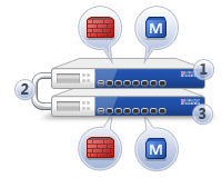
Installing Full High Availability Appliances
- Security Management server and Security Gateway are each installed on one appliance, and two appliances work in High Availability mode. One is active, and one is standby.
|
Item
|
Description
|
1
|
Primary appliance
|
2
|
Direct appliance to appliance connection
|
3
|
Backup appliance
|
|
Security Gateway component
|
|
Security Management Server component
|
- If the active member has a failure that affects the Security Management server and the Security Gateway, they failover to the standby.
- If the Security Management server on the active member experiences a failure, only the Security Management server fails over to the standby. The Security Gateway on the first member continues to function.
- If the Security Gateway on the active member experiences a failure, only the Security Gateway fails over to the standby. The Security Management server on the first member continues to function.
After you install the Gaia or SecurePlatform operating system, configure Standalone Full HA. First, configure each of the two standalone appliances with its First Time Configuration Wizard. Then configure the High Availability options in SmartDashboard.
Gaia Appliances
Some appliances have a dedicated SYNC interface that is used to synchronize with the other appliance. If there is no SYNC interface on the appliance, use the ETH1 interface.
|
Note - The internal interface (INT) on a UTM-1 appliance is used as the management interface.
|
To start the First Time Configuration Wizard:
- Connect a standard network cable to the appliance management interface and to your management network.
The management interface is marked . This interface is preconfigured with the IP address 192.168.1.1
- Connect to the management interface from a computer on the same network subnet.
For example: IP address 192.168.1.x255.255.255.0
- To access the management interface, open a connection from a browser to the default management IP address:
https://192.168.1.1 - The login page opens. Log in to the system using the default username and password:
admin admin - Click .
|
Note - The features configured in the First Time Configuration Wizard are accessible after completing the wizard using the WebUI menu. The WebUI menu can be accessed by navigating to https://<appliance_ip_address>
|
- The runs.
To configure Gaia Full HA appliances:
- In the First Time Configuration Wizard, set the username and password for the administrator account and then click .
- Set the date and time manually, or enter the hostname, IPv4 address or IPv6 address of the NTP server and then click .
- Set the for the appliance.
- Optional: Set the , and IPv4 or IPv6 addresses for the .
Click .
- Set an IPv4 and an IPv6 address for the management interface, or set one IP address (IPv4 or IPv6).
If you change the management IP address, the new IP address is assigned to the interface. The old IP address is added as an alias and is used to maintain connectivity.
- Select and .
- Configure these settings:
Click .
- Set the username and password for the Security Management server administrator account and then click .
- Define the GUI Clients that can log in to the Security Management server. If you choose or , define an IPv4 or an IPv6 address. Click
- Click and then click OK.
- If the window shows, click or as necessary.
Gaia R76 is installed on the appliance.
- Log in to the Gaia WebUI with the new management IP address that you entered in the First Time Configuration Wizard.
- Double-click the or interface and configure the settings. This interface is used to synchronize with the other appliance. Click .
- Configure the settings for other interfaces that you are using.
- Use a cross-over cable to connect the or interfaces on the appliances.
- Do steps 1 - 15 again for the secondary appliance, with these changes:
- If necessary, download SmartConsole from the Gaia WebUI.
- Open a connection from a browser to the WebUI at
https://<management_ip_address> - In the page, click .
SecurePlatform Appliances
Some appliances have a dedicated SYNC interface that is used to synchronize with the other appliance. If there is no SYNC interface on the appliance, use the ETH1 interface.
|
Note - The internal interface (INT) on a UTM-1 appliance is used as the management interface.
|
To start the First Time Configuration Wizard:
- Connect a standard network cable to the appliance management interface and to your management network.
The management interface is marked .
- Open Internet Explorer to the default management IP address,
https://192.168.1.1:4434 - Log in to the system using the default login name/password: .
|
Note - You can use the WebUI menu to configure the appliance settings. Navigate to https://<appliance_ip_address>:4434
|
- Set the username and password for the administrator account.
- Click .
The First Time Configuration Wizard opens.
To configure Full High Availability:
- In the First Time Configuration Wizard, set the date and time and then click .
- Configure the settings for the network connections.
- Click the interface and configure the settings and then click .
- Click the or interface and configure the settings and then click . This interface is used to synchronize with the other appliance.
- Configure the settings for other interfaces that you are using.
Click .
- Configure the settings for the routing table and then click .
- Set the (required), (optional), and (optional) and then click .
- Select and then click .
- Configure the appliance as the primary cluster member.
- Select .
- Select .
Click .
- Set the clients that can manage the appliance using a web or SSH connection and then click .
- Download SmartConsole and then click .
The window shows the settings for the appliance.
- Click .
SecurePlatform R76 is installed on the primary appliance.
- Use a cross-over cable to connect the or interfaces on the appliances.
- Do steps 1 - 9 again for the secondary appliance, with these changes:
Configuring Standalone Full High Availability
After you set up the appliances for Standalone Full High Availability, configure this deployment in SmartDashboard. You must configure both cluster members before you open the cluster configuration wizard in SmartDashboard.
The LAN1 interface serves as the SYNC interface between cluster members. If not configured, SYNC interfaces are automatically set to 10.231.149.1 and 10.231.149.2. If these addresses are already in use, their values can be manually adjusted. If you manually adjust the default IP SYNC addresses, verify that both reside on the same subnet.
|
Note - All interfaces in the cluster must have unique IP addresses. If the same IP address is used twice, policy installation will fail. A Load on gateway failed error message is displayed.
|
The cluster has a unique IP address, visible to the internal network. The unique Virtual IP address makes the cluster visible to the external network, and populates the network routing tables. Each member interface also has a unique IP address, for internal communication between the cluster members. These IP addresses are not in the routing tables.
To configure Standalone Full High Availability:
- Open SmartDashboard.
- Connect to the primary appliance and then click to accept the fingerprint as valid.
The opens.
Click .
- Enter the name of the Standalone Full High Availability configuration and then click .
- Configure the settings for the secondary appliance.
- In , enter the hostname.
- In, enter the IP address of the management interface.
- Enter and confirm the SIC activation key.
Click .
- Configure the IP address of the paired interfaces on the appliances. Select one of these options:
- - Enter a virtual IP address for the interface.
- - Configure the interface as the synchronization interface for the appliances.
- - Use the configured IP address of this interface.
Click .
- Do step 5 again for all the interfaces.
- Click .
Removing a Cluster Member
You can remove one of the two members of a cluster without deleting the cluster object. A cluster object can have only a primary member, as a placeholder, while you do maintenance on an appliance. You must remove the cluster member in the WebUI and in the CLI.
To remove a cluster member:
- Open the WebUI of the member to keep.
- Open Product Configuration > Cluster.
- Click Remove Peer.
- If the current member is the primary member, the secondary member is deleted.
- If the current member is the secondary member, the secondary member is promoted to primary. Then the peer is deleted.
Services running on the appliance are restarted.
- On the appliance command line, run:
cp_conf fullha disableThis command changes back the primary cluster member to a standalone configuration.
- Reboot.
The former cluster object is now a locally managed gateway and Security Management server.
Adding a New Appliance to a High Availability Cluster
You can add a standalone appliance to a cluster, after the High Availability cluster is defined. You can change which member is primary.
To add an existing appliance to a cluster:
- Open the WebUI of the appliance.
- On the Product Configuration, Cluster page, select Make this Appliance the primary member of a High Availability Cluster.
- Click Apply.
- Reboot the appliance.
- In SmartDashboard, open the object of the primary member.
The first-time cluster configuration wizard opens.
- Complete the wizard to configure the secondary cluster member.
Troubleshooting network objects:
In SmartDashboard, the network object of the standalone appliance is converted to a cluster object. If the standalone appliance was in the Install On column of a rule, or in the Gateways list of an IPSec VPN community, the cluster object is updated automatically. For all other uses, you must manually change the standalone object to the cluster object. These changes can affect policies.
To see objects and rules that use the object to change:
- Right-click the standalone object and select .
- Select a line and click .
- In the window that opens, replace the standalone object with the cluster object.
If the line is a:
- - Browse through the pages of the properties window that opens, until you find the object to change.
- Policy (for example, ) - Open the Gateways page of the Software Blade. Remove the standalone object. Add the cluster object.
- In > , see the rules that use the standalone object.
- Select each rule and click .
- Edit those rules to use the cluster object.
|
Note - The icon in SmartDashboard changes to show new status of the appliance as a primary cluster member. The Name and UID of the object in the database stay the same.
|
Recommended Logging Options for High Availability
In High Availability, log files are not synchronized between the two cluster members. For this reason, we recommend that you configure the logs of the cluster.
To forward cluster logs to an external log server:
- Open the properties of the cluster object.
- Open > .
- Click , and select the Log Server.
- Select or define a time object for .
Or:
Configure SmartEvent and SmartReporter with standard reports, to use only one of the cluster members as a source for log file correlation and consolidation.
Deploying Bridge Mode Security Gateways
If you install a new Security Gateway in a network and cannot change the IP routing scheme, use bridge mode. A Security Gateway in bridge mode is invisible to Layer-3 traffic. When authorized traffic arrives, the Security Gateway passes it to the next interface through bridging. This creates a Layer-2 relationship between two or more interfaces. Traffic that enters one interface exits the other interface. Bridging lets the Security Gateway inspect and forward traffic, without the original IP routing.
|
|
|
|
Before
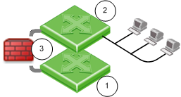
|
After
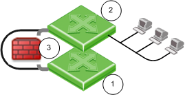
|
Item
|
Description
|
1
|
Switch 1
|
2
|
Switch 2
|
3 before
|
Connection between switches, one IP address.
|
3 after
|
Security Gateway Firewall bridging Layer-2 traffic over the one IP address, with a subnet on each side using the same address.
|
Before configuring the bridge, install the Security Gateway.
To manage the gateway in bridge mode, it must have a separate, routed IP address. You must configure the bridged interfaces.
Gaia
You can configure bridge mode in the Gaia WebUI or the CLI.
To configure a bridge interface in the WebUI:
- In the WebUI navigation tree, select .
- Click > , or select an interface and click .
The (or ) window opens.
- On the tab, enter or select a ID (unique integer between 1 and 1024).
- Select the interfaces from the list and then click .
- Click the or tabs, and then enter the IP addresses and subnet.
Or click .
- Click .
To configure a bridge interface with the CLI:
- Run:
add bridging group<Group Name> interface <physical interface name> - Run again for each interface in the bridge.
- Run:
save config - Add a bridge interface IP address:
- IPv4:
set interface <Group Name> ipv4-address <IP> subnet-mask <Mask> - IPV6:
set interface <Group Name> ipv6-address <IP> mask-length <Prefix>
- Run:
save config
SecurePlatform
You can configure bridge mode in the SecurePlatform WebUI or the CLI.
To configure a bridge interface in the SecurePlatform WebUI:
- Connect to the management interface of the Security Gateway.
- Select Network > Connections > New > Bridge.
- Select the two interfaces of the bridge and click Add.
- Enter the IP Address and Netmask of the bridge (not the physical) interface.
- Select Apply.
To configure a bridge interface in the Command Line:
- Enter:
sysconfig - Select Network Connections > Add new connection > Bridge.
- Add a pair of interfaces which are not configured with an IP address to the bridge.
- Enter:
N - Enter the IP address and netmask of the bridge (not the physical) interface.
If anti-spoofing is required for the bridged interfaces, define different IP address ranges behind each bridged interface. Do not use the same network for the two interfaces, as this can cause a loss of connectivity.
To see the bridge status:
The brctl show command displays the status of the bridge configuration. For example:
[Expert@GW-1]# brctl show
bridge name bridge id STP enabled interfaces
br0 8000.000423b93e56 no eth0 eth1
|
The are the two bridged interfaces. The MAC address of the bridge is inherited from one of the physical interfaces.
Installing Management High Availability
- A Primary and Secondary Security Management server are configured. The databases of the Security Management servers are synchronized, either manually or on a schedule, so they can back up one another. The administrator makes one Security Management server Active and the other(s) Standby. If the Active Security Management server is down, the administrator can make the Standby server Active.
|
|
|
|
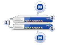
|
Item
|
Description
|
1
|
Primary Security Management server
|
2
|
Direct or indirect Security Management server to Security Management server connection
|
3
|
Secondary Security Management server
|
|
|
Security Management server component
|
You can configure Management High Availability between:
- Smart-1 appliances.
- Security Management servers on open servers.
- Security Management servers on standalone open servers. However, there is no High Availability between the Security Gateways.
Prerequisites for Management High Availability
- The Primary and Secondary Security Management servers must:
- Be installed using the same ISO, or upgraded in the same way.
- Have the same Check Point version.
- Have the same Hotfixes installed.
- SmartEvent is not supported in a Management HA configuration.
Workflow for Installing and Configuring Management High Availability:
- Install and configure the primary Security Management Server:
- Open server only: Install the operating system (Gaia, SecurePlatform or Windows).
- Configure the primary Security Management Server:
- Gaia: Use the First Time Configuration Wizard.
- SecurePlatform: Use
cpconfig - Windows: when choosing installation options.
- Install and configure the secondary Security Management Server:
- Open server only: Install the operating system (Gaia, SecurePlatform or Windows).
- Configure the secondary Security Management Server:
- Gaia: Use the First Time Configuration Wizard.
- SecurePlatform: Use
cpconfig - Windows: when choosing installation options.
For instructions on installing and configuring the primary and secondary Security Management server see the applicable section:
To learn how to synchronize the databases of the Security Management servers and make one Active and the other(s) Standby, see the R76 Security Management Administration Guide.
Installing SmartConsole Clients
The SmartDashboard and other SmartConsole applications are the GUI clients to manage the Security Management server and Security Gateways.
For SmartConsole requirements, see the R76 Release Notes.
To install the SmartConsole clients on Windows platforms:
- Insert the R76 distribution media or download the SmartConsole application from the Support Center.
- If you are using the installation media, go to the
Linux\linux\windows - Run the executable.
- Continue with the instructions on the screen.
Demo Mode
You can open the SmartDomain Manager in Demo mode. This mode does not require authentication or a connection to the Multi-Domain Server. Use the Demo mode to experiment with different objects, views, modes and features before you create a production system. The Demo mode includes several pre-configured sample Domains, Domain Management Servers, Security Gateways and policies.
Operations performed in Demo mode are stored in a local database. You can continue a Demo session from the point at which you left off in a previous session.
Logging in to SmartConsole
You connect to the Security Management server using SmartDashboard or other SmartConsole clients. Security Management server authenticates the connection when you log in for the first time.
You can create a new certificate for future logins. For more about certificates, see the R76 Security Management Administration Guide.
To log in to SmartConsole clients:
- Open the SmartConsole from the menu.
- To log in to the Security Management server:
- To use a password, enter the Security Management server host name or IP address. Then enter your administrator user name and password.
- To use a certificate, enter the Security Management server host name or IP address. Then click and select the certificate.
To experiment with pre-configured sample objects, views, modes and features, select .
- Optional: Enter a description of this session.
- Optional: Select . This option lets you connect to the Security Management server while other administrators are connected. You cannot change settings in this mode.
- Click .
- If necessary, confirm the connection using the fingerprint generated during installation.
You see this only the first time that you log in from a client computer.
Post-Installation Configuration
You can use the Check Point configuration tool (cpconfig) to configure settings after installation:
- Licenses and Contracts: Add or delete licenses for the Security Management server and Security Gateways.
- Administrators: Define administrators with Security Management server access permissions. These administrators must have Read/Write permissions to create the first security policy.
- GUI Clients: Define client computers that can connect to the Security Management server using SmartConsole clients.
- Certificate Authority: Starts the Internal Certificate Authority, which allows makes connections between the Security Management server and gateways. For Windows, you must define the name of the ICA host. You can use the default name or define your own. The ICA name must be in the
host name.domainica.checkpoint.com - Fingerprint: Save the certificate fingerprint when you log in to SmartConsole clients for the first time.
Enabling IPv6 on Gaia
IPv6 is automatically enabled if you configure IPv6 addresses in the First Time Configuration Wizard.
If you did not do this, enable IPv6 in one of the following ways:
To enable IPv6 using clish:
- Run:
set ipv6-state on Run:
save config- Run:
reboot
To enable IPv6 using the WebUI:
- In the WebUI navigation tree, select .
- For , select .
Where to Go From Here
You have learned the basics necessary to get started. Your next step is to get more advanced knowledge of your Check Point software.
Documentation is available on your Check Point DVD and on the R76 home page.
For more technical information about Check Point products, go to the Check Point Support Center.
Uninstalling R76
A command line uninstall utility for Windows and Linux open servers performs a silent uninstallation of the release.
|
Important - This does not remove Multi-Domain Security Management products.
|
To uninstall the release on SecurePlatform or Gaia appliances and open servers, use the built-in Backup and Restore functionality.
To uninstall R76 on Windows and Linux:
Platform
|
Procedure
|
Windows
|
- Open Start > Check Point > Uninstall R76
- At the prompt, enter Y to continue.
|
Linux
|
- Change directory to:
/opt/CPUninstall/R76/ - Run:
./UnixUninstallScript
|
Example of Uninstall output for Windows:
***********************************************************
Welcome to Check Point R76 Uninstall Utility
***********************************************************
All R76 packages will be uninstalled.
Uninstallation program is about to stop all Check Point processes.
Do you want to continue (y/n) ? y
Stopping Check Point Processes...Done!
Uninstalling Management Portal package...Done!
Uninstalling SmartEvent and SmartReporter Suite package...Done!
Uninstalling R75 Compatibility package...Done!
Uninstalling R75.20 Compatibility package...Done!
Uninstalling R75.40 Compatibility package...Done!
Uninstalling R75.40VS Compatibility package...Done!
Uninstalling R71 Compatibility package...Done!
Uninstalling CPSG 80 Series compatibility package...Done!
Uninstalling SFW R75 Compatibility Package package...Done!
Uninstalling Connectra R66 Compatibility package...Done!
Uninstalling NGX Compatibility package...Done!
Uninstalling V40 Compatibility package...Done!
Uninstalling UTM-1 Edge compatibility package...Done!
Uninstalling SmartLog package...Done!
Uninstalling CPinfo package...Done!
Uninstalling Unified EndPoint Security Management package...Done!
Uninstalling Security Gateway / Security Management package...Done!
************************************************************************
Package Name Status
------------ ------
Management Portal Succeeded
SmartEvent and SmartReporter Suite Succeeded
R75 Compatibility Succeeded
R75.20 Compatibility Succeeded
R75.40 Compatibility Succeeded
R75.40VS Compatibility Succeeded
R71 Compatibility Succeeded
CPSG 80 Series compatibility Succeeded
SFW R75 Compatibility Package Succeeded
Connectra R66 Compatibility Succeeded
NGX Compatibility Succeeded
V40 Compatibility Succeeded
UTM-1 Edge compatibility Succeeded
SmartLog Succeeded
CPinfo Succeeded
Unified EndPoint Security Management Succeeded
Security Gateway / Security Management Succeeded
************************************************************************
Uninstallation program completed successfully.
Do you wish to reboot your machine (y/n) ?
|
If any package fails to uninstall, the script generates a log file and prints its location on the screen.
|
|
