


|
|
|
In This Section: |
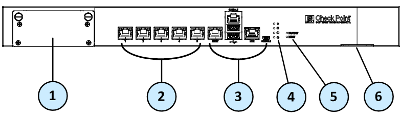
Check Point 5100 and 5200
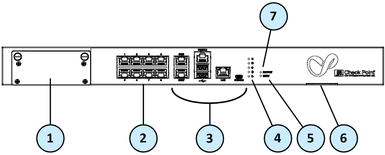
Check Point 5400 and 5600
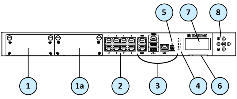
Check Point 5800 and 5900
Item |
Component |
Description |
|---|---|---|
1 |
Expansion line card |
Expansion slot. |
1a |
Expansion line card |
5800 and 5900 appliances - Expansion slot. |
2 |
On board LAN ports |
5100 and 5200 appliances - Five 10/100/1000Base-T RJ-45 ports. 5400, 5600, 5800, and 5900 appliances - Eight 10/100/1000Base-T RJ-45 ports. |
3 |
Appliance ports |
Use these ports to connect to the appliance. |
4 |
System LEDs |
System power, storage device activity, power supply status (in the 5600, 5800, and 5900 appliances only), alert, and location. |
5 |
Reset
|
Insert a pin for 5 to 8 seconds to perform a hardware reset. 5100, 5200, 5400, and 5600 appliances - Insert a pin to restore the appliance to its factory defaults. 5800 and 5900 factory defaults can be restored from the LCD. |
6 |
Identification service tag |
A slide out card that identifies the appliance and shows its serial number, MAC address, and model number. |
7 |
LCD screen |
Allows system monitoring and configuration (in the 5800 and 5900 appliances only). |
8 |
Keypad |
Use the buttons to control the LCD screen (in the 5800 and 5900 appliances only). |
Item |
Component |
Description |
|---|---|---|
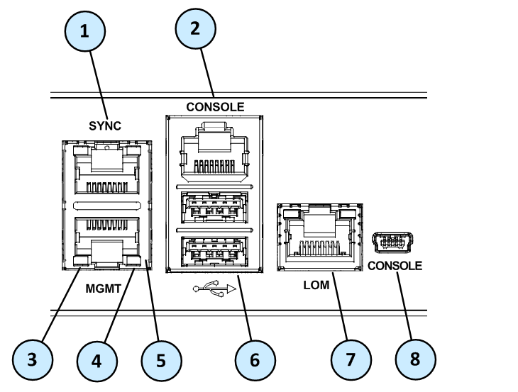
1 |
Synchronization port |
Synchronize with cluster members or a High Availability peer (available in the 5400, 5600, 5800, and 5900 appliances). |
2 |
RJ45 console port |
For a serial connection to the appliance. See Connecting to the 5000 Appliances CLI. |
3 |
Port activity LED |
|
4 |
Link LED |
|
5 |
Management port |
For an Ethernet connection to a remote management computer. |
6 |
USB ports |
2 USB ports. |
7 |
LOM port |
LOM (Lights Out Management) port to connect to the LOM card. Optional for 5100, 5200, and 5400 appliances. |
8 |
MiniUSB console port |
For a serial connection to the appliance. |
The 5000 appliance series includes front panel LEDs to monitor system status.
In addition, the 5800 and 5900 appliances include an LCD screen for enhanced system monitoring and configuration.
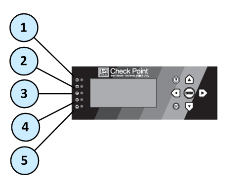
Item |
Icon |
Component |
Description |
|---|---|---|---|
1 |
|
System power |
|
2 |
|
Storage device activity |
|
3 |
|
Power supply status |
5600, 5800, and 5900 only
|
4 |
|
Alert |
|
5 |
|
Location |
|
The 5800 and 5900 appliances have an LCD panel that you can use to do these basic management operations:
For more information, see the Gaia Administration Guide for your version.
Menu Options
Menu |
Sub-menu |
Purpose |
|---|---|---|
Network |
|
|
|
Set Mgmt IP |
Set the management interface IP address. |
|
Set Netmask |
Set the management interface Netmask. |
|
Set Default GW |
Set the management interface default gateway. |
System |
|
|
|
Reboot |
Reboot the appliance. |
LCD Panel Buttons
To |
Press |
|---|---|
Enter the main menu |
Any button, other than |
Navigate the menu |
|
Change a number |
|
Select a menu option |
|
Go back to previous menu |
|
When Entering an IP Address
To |
Press |
|---|---|
Move to the next digit |
|
Move back to the previous digit |
|
Approve the change |
|
Cancel the IP change |
|
Change current digit |
|
5800 Appliance Rear Panel
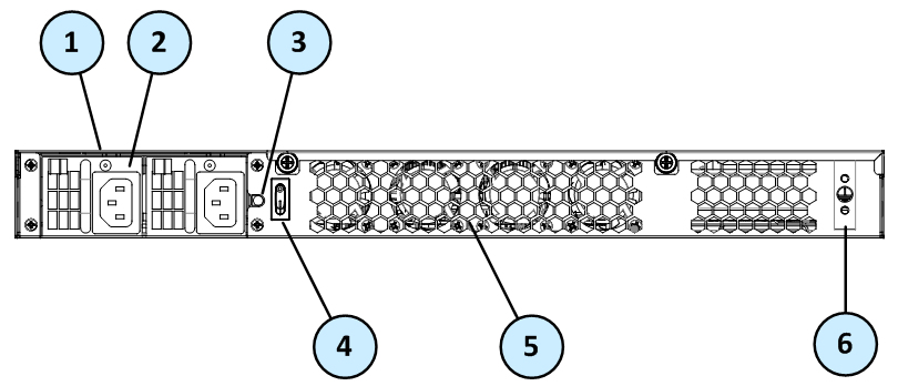
5900 Appliance Rear Panel
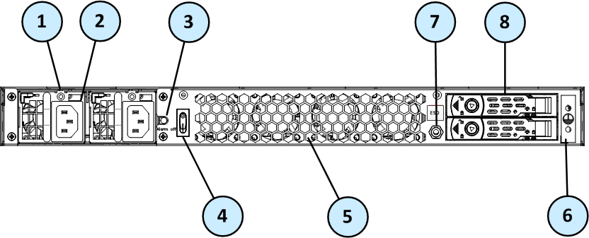
Differences in other 5000 appliances are described in the table.
Item |
Component |
Description |
|---|---|---|
1 |
LED indicator for each power supply unit |
In 5100, 5200, and 5400 appliances:
In 5600, 5800, and 5900 appliances:
|
2 |
Power supply units |
Connect to an electric outlet. One module is included. An optional dual redundant hot-swappable power supply is available in the 5600, 5800, and 5900 appliances. You can use the cable restraints to avoid accidental removal of the power supply cable. |
3 |
Alarm off button for power supply units |
If a power supply cable is not connected to the outlet, an alarm sounds continuously. Press this button to turn off the alarm. |
4 |
Main power switch |
|
5 |
Fixed cooling fans |
Numbered from right to left. In the 5100, 5200, 5400, and 5600 appliances - |
6 |
Grounding lug |
When using a DC power supply unit (PSU), use the grounding lug that is located on the DC PSU. |
7 |
ESD grounding plug |
When servicing the appliance, connect an ESD strap to this plug (in 5900 appliances only). |
8 |
Storage devices |
When monitoring the storage devices with the |
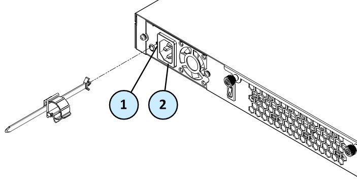
On 5100, 5200, and 5400 appliances, you can use the power cable restraint to prevent accidental removal of the power cable.
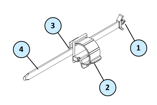
Item |
Description |
|---|---|
1 |
Restraint anchor |
2 |
Cable loop |
3 |
Restraint strip tab |
4 |
Restraint strip |
Item |
Description |
1 |
Restraint strip slot |
2 |
Power supply inlet |
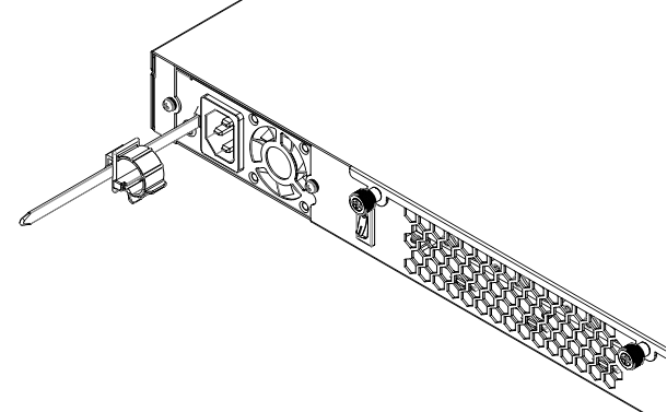
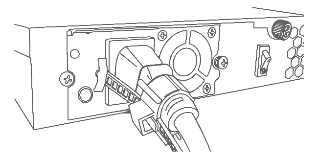
To install the power cable restraint:
The 5600, 5800, and 5900 appliances have a power cable restraint clip attached to the power supply unit (PSU). Use the restraint clip to prevent accidental removal of the power cable.
To secure the restraint clip on the power supply cable:
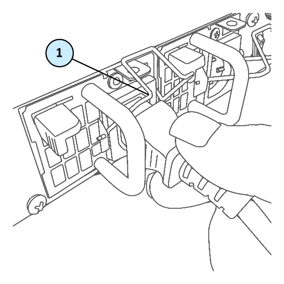
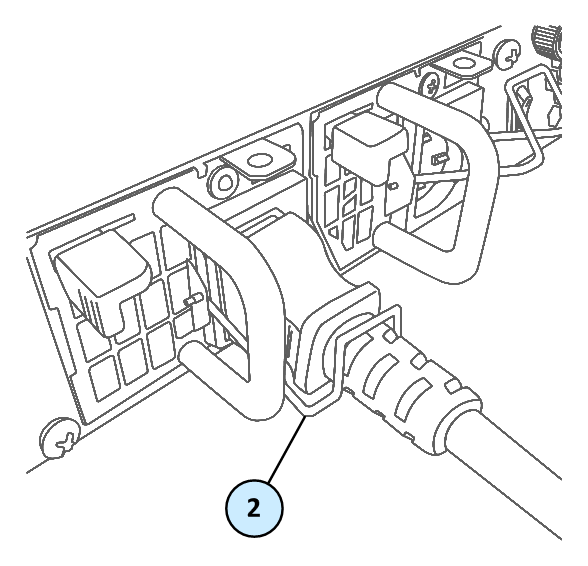
Item |
Description |
1 |
Restraint clip in the open position (upward) |
2 |
Restraint clip in the closed position |
The Check Point Lights Out Management (LOM) card lets you use a dedicated management channel to remotely control Check Point appliances. Lights Out Management can also work when the appliance is turned off or not responding.
Lights Out Management is an optional feature on the 5100, 5200, 5400, and 5600 appliances. It is included by default with the 5800 and 5900 appliances.
For more about using Lights Out Management, see the Lights Out Management Administration Guide.
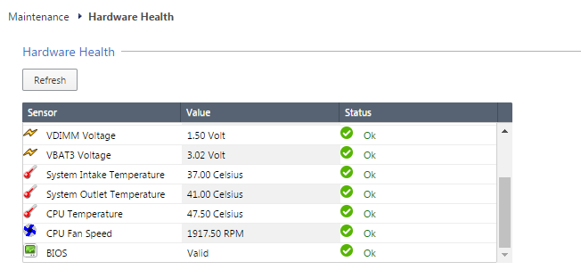
To ensure resilience in the event of a BIOS failure, 5000 Appliances are equipped with dual redundant BIOS images.
If an appliance encounters a BIOS failure, it will boot up from a recovery, read-only BIOS image that enables full functionality of the appliance.
These notifications are shown in the event of a BIOS failure:
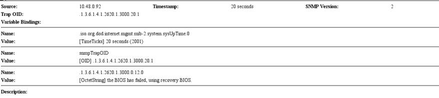
To recover from a BIOS failure, see sk108517 or contact Check Point support. The appliance is fully functional until the BIOS recovery is completed.
The 5000 Appliances has parts that you can easily replace to minimize downtime. There are also components that you can install to upgrade the appliance. These are the parts and components that can be used with the appliance:
For more information about installing these parts and components, see the appliance home page.
Unless directed to do so by Check Point technical support, you are prohibited by warranty and support agreements from replacing any parts.


