


|
|
|
In This Section: |
The line drawing shows the front panel elements in the 16000 appliance.

Item |
Component |
Description |
|---|---|---|
1 |
Service tag |
A slide out card that identifies the appliance and shows its serial number and MAC address. |
2 |
Locator button |
Turns the location beacon LED on and off in the appliance. |
3 |
System LEDs |
|
4 |
Reset |
Insert a pin for 5 to 8 seconds to perform a hardware reset. |
5 |
USB Type-C port |
For a serial connection to the appliance. |
6 |
RJ45 Console port and |
RJ45 port for a serial connection to the appliance. |
7 |
LOM port |
LOM (Lights Out Management) port to connect to the LOM card. Note - In 16000 Base appliances, LOM is optional by default. |
8 |
Management and Synchronization ports |
The top synchronization port synchronizes with cluster members or a High Availability peer. |
9 |
ESD grounding point |
When servicing the appliance, connect an ESD strap to this point. |
10 |
2 Storage devices |
When monitoring the storage devices with the Note - 16000 Base appliances are supplied with one storage device by default. |
11 |
Storage device power LED |
|
12 |
Storage device activity LED |
|
13 |
4 Expansion line cards |
4 expansion slots. |
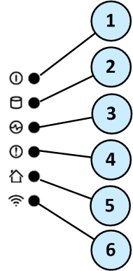
Item |
Icon |
Component |
Description |
|
|---|---|---|---|---|
1 |
|
System power |
|
|
2 |
|
Storage device activity |
|
|
3 |
|
Power supply status |
|
|
4 |
|
Alert |
|
|
5 |
|
Location beacon |
Note - Turn off the Location beacon LED the same way you turned it on |
|
6 |
|
WiFi |
Not supported
|
|
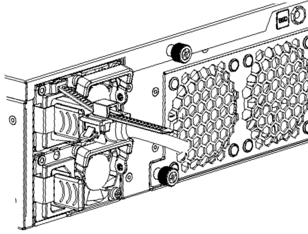
The line drawing shows the rear panel elements in the 16000 appliance.

Item |
Component |
Description |
|---|---|---|
1 |
Cover screws |
Loosen screws to remove the cover of the appliance. |
2 |
ESD grounding point |
When servicing the appliance, connect an ESD strap to this point. |
3 |
Alarm Off button for power supply units |
If a power supply cable is not connected to the outlet, an alarm sounds continuously. Press this button to turn off the alarm. Note that this button is functional immediately after powering up the appliance. |
4 |
Grounding lugs |
Used to connect grounding. |
5 |
LED indicator for each power supply unit |
|
6 |
Power supply units |
Dual redundant power supplies that you can hot swap. Each power supply unit connects to an electric outlet. You can use the cable restraints to avoid accidental removal of the power supply cable. The PSUs are numbered from top to bottom in the OS as Power Supply #1 and Power Supply #2 . Note - 16000 Base appliances that use AC PSUs, contain one AC PSU and one dummy filler. See also PSU Configuration and Monitoring. |
7 |
Thumb screws for cooling fan unit |
Loosen screws to remove cooling fan unit from the appliance. |
8 |
Cooling fan units |
Numbered from right to left: |
9 |
Location LED |
Note - Turn off the Location LED the same way you turned it on |
10 |
Main power switch |
When the appliance is turned off, turns the appliance on. When the appliance is turned on, pressing and releasing the switch will start an orderly shutdown process. Alternatively, holding the switch for 4 seconds will force a machine shut down. |
You can use the power cable restraint to prevent accidental removal of the power cable.
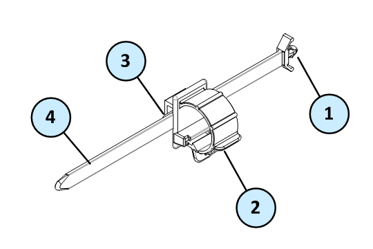
Item |
Description |
|---|---|
1 |
Restraint anchor |
2 |
Cable loop |
3 |
Restraint strip tab |
4 |
Restraint strip |
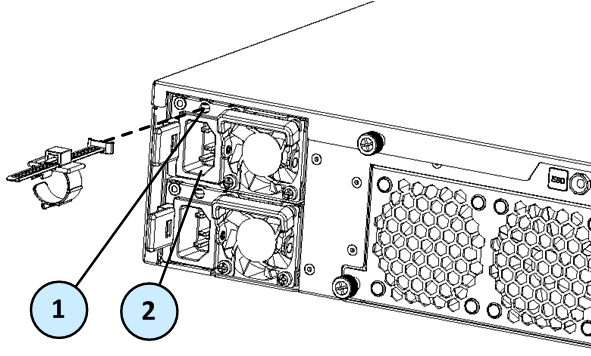
Item |
Description |
|---|---|
1 |
Restraint strip slot |
2 |
Power supply inlet |
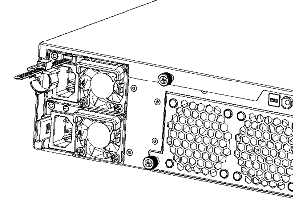
To install the power cable restraint:
The Check Point Lights Out Management (LOM) card lets you use a dedicated management channel to remotely control Check Point appliances. Lights Out Management can also work when the appliance is turned off or not responding. However, the appliance must be connected to a power source.
For more about using Lights Out Management, see the Lights Out Management Administration Guide.
To ensure resilience in the event of a BIOS failure, 16000 Appliances are equipped with dual redundant BIOS images.
If an appliance encounters a BIOS failure, it will boot up from a recovery, read-only BIOS image that enables full functionality of the appliance.
These notifications are shown in the event of a BIOS failure:
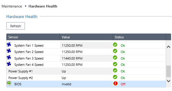
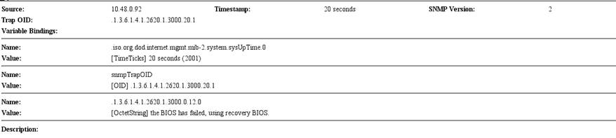
To recover from a BIOS failure, see sk108517 or contact Check Point support. The appliance is fully functional until the BIOS recovery is completed.
These are the supported PSU configurations for the 16000 appliance models and PSU types:
PSU Type |
16000 Base |
16000 Plus |
16000 Turbo |
||
|---|---|---|---|---|---|
AC PSU |
1 AC PSU 1 Dummy filler |
2 AC PSUs |
2 AC PSUs |
||
DC PSU |
2 DC PSUs |
2 DC PSUs |
2 DC PSUs |
||
|
Important - All PSUs on an appliance must be of the same type, either all AC or all DC. |
||||
When a PSU is functioning correctly: the PSU LED is green, the Alert LED is not blinking due to a PSU issue (might still be blinking due to other errors), and there is no SNMP alarm.
When a PSU is not functioning correctly: the PSU LED is amber, the Alert LED is blinking due to a PSU issue, and an SNMP alarm is sent.
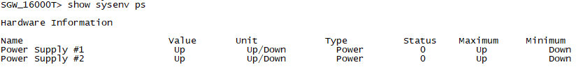
To monitor the PSUs through the CLI:
show sysenv ps
Sample output for a 16000 Turbo appliance:
Where:
Column |
Description |
|---|---|
|
Power Supply #1 - The PSU in the top PSU slot. Power Supply #2 - The PSU in the bottom PSU slot. |
|
Up - The PSU slot contains a PSU is up. Down - The PSU slot contains a PSU and it is not connected to a power source. Empty - There is nothing in the PSU slot. Dummy - The PSU slot contains a dummy filler (only supported for 1 PSU slot in 16000 Base of AC PSU type. |
|
Up/Down - The type of measure unit used for PSUs is either Up or Down. |
|
Power - The type of sensor is power supply. |
|
0 - Denotes no problems found. 1 - Denotes an error. |
|
Denotes the maximum and minimum thresholds. For PSUs they are only measured as Up and Down. |
The 16000 appliance has parts that you can easily replace to minimize downtime. There are also components that you can install to upgrade the appliance. These are the parts and components that can be used with the appliance:
For more information about installing these parts and components, see the appliance home page.
Unless directed to do so by Check Point technical support, you are prohibited by warranty and support agreements from replacing any parts.


