


|
|
|
In This Section: |
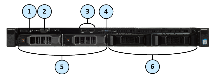
Item |
Component |
Icon |
Description |
|---|---|---|---|
1 |
Power-on indicator, Power button |
|
Lets you know the power status of the system. The power-on indicator glows when the system power is on. The power button controls the power supply output to the system. |
2 |
VGA Port |
|
Lets you connect a display to the system. |
3 |
USB connectors |
|
Let you connect USB devices to the system. The ports are USB 2.0-compliant. |
4 |
Service tag |
|
The service tag contains the MAC address, serial number, and the appliance model. The service tag is a slide-out label panel. |
5 |
Storage device slots |
|
Smart-1 525 supports 2 drives. See Storage Devices and Smart-1 525, 5050 and 5150 Installing and Removing Storage Devices. |
6 |
Disk blanks |
|
Cover the empty disk slots. |
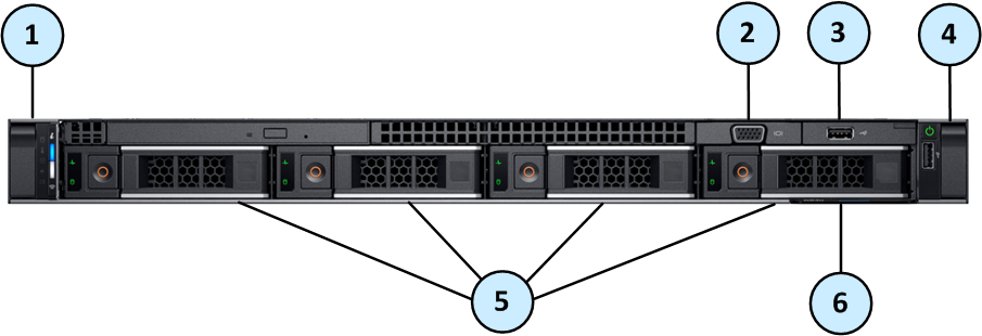
Item |
Component |
Description |
|---|---|---|
1 |
Left control panel |
Contains the status LED indicators and system notification LED indicator. |
2 |
VGA port |
Enables you to connect a display device to the system. For more information, see the Technical specifications section. |
3 |
USB port |
The USB port is USB 2.0 compliant. |
4 |
Right control panel |
Contains the power button and a USB 2.0 compliant port. |
5 |
Disk slots |
Smart-1 5050 is supplied with 4 disk drives. See Smart-1 525, 5050 and 5150 Installing and Removing Storage Devices. |
6 |
Service tag |
The service tag contains the MAC address, serial number, and the appliance model. The service tag is a slide-out label panel. |
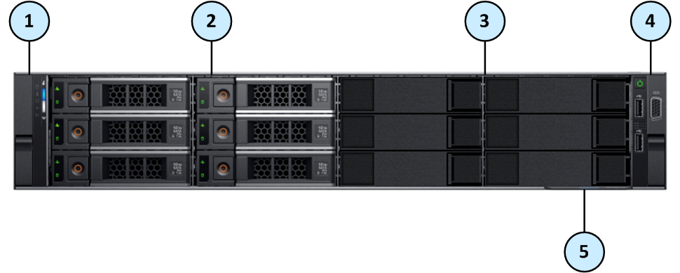
Item |
Component |
Description |
|---|---|---|
1 |
Left control panel |
Contains the status LED indicators and system notification LED indicator. |
2 |
Disk slots |
Enable you to install storage devices that are supported on your system. Smart-1 5150 is supplied with 6 or 12 disks. You can install up to 6 additional disks if your system starts with 6 disks. See Smart-1 525, 5050 and 5150 Installing and Removing Storage Devices. |
3 |
Disk blanks |
Disk blanks that cover the empty disk slots. |
4 |
Right control panel |
Contains the power button, two USB 2.0 ports, and a VGA connector. |
5 |
Service tag |
The service tag contains the MAC address, serial number, and the appliance model. The service tag is a slide-out label panel. |
RAID Levels and Disk Storage
|
Smart-1 525 |
Smart-1 5050 |
Smart-1 5150 |
|---|---|---|---|
Default |
1 |
10 |
6 for 6, 8, 10 disks 60 for 12 disks |
Supported |
1 |
5, 10 |
5 for 6, 8, 10, 12 disks 6 for 6, 8, 10, 12 disks 10 for 8, 12 disks 50 for 6, 8, 10, 12 disks 60 for 8, 10, 12 disks |
Default Storage |
2 x 4TB disks |
4 x 4TB disks |
6 x 4TB disks |
Optional Storage |
N/A |
N/A |
+2, +4, +6 x 4TB disks |
Numbering of the Disk Slots on the Front Panel
Slot 0: |
Slot 1: |
Slot 2: |
Slot 3: |
Note - Only Slot 0 and Slot 1 are supported in Smart-1 525.
Do not install a disk in Slot 2 or Slot 3. If you do so, your appliance will show this error:Disk slot occupation mismatch!!Only use of slot 0 and 1 is supported.
Slot 0: |
Slot 1: |
Slot 2: |
Slot 3: |
Note - See the slot numbers below the bottom row of disk slots on the appliance.
Slot 0: |
Slot 3: |
Slot 6: |
Slot 9 |
Slot 1: |
Slot 4: |
Slot 7: |
Slot 10: |
Slot 2: |
Slot 5: |
Slot 8: |
Slot 11: |
Note - See the slot numbers below the bottom row of disk slots on the appliance.
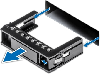
Disk Carrier
Item |
Description |
|---|---|
1 |
Status indicator LED. |
2 |
Activity indicator LED. |
3 |
Release button. |
4 |
Release handle. |
5 |
Disk. |
Status indicator LED patterns
Status Indicator |
Disk Condition |
|---|---|
Steady green |
Disk is online. |
Flashes green twice per second |
Identifying disk or preparing disk for removal. |
Blinks green, amber, and then turns off |
Predicted disk failure. |
Blinks amber four times per second |
Disk failed. |
Blinks green slowly |
Disk is rebuilding. |
Blinks green for three seconds, blinks amber for three seconds, then turns off after six seconds |
Disk rebuild stopped. |
Off |
Disk is ready for insertion or removal. The status indicator LED remains off until all disks are initialized after the system is turned on. Disks are not ready for insertion or removal during this time. |
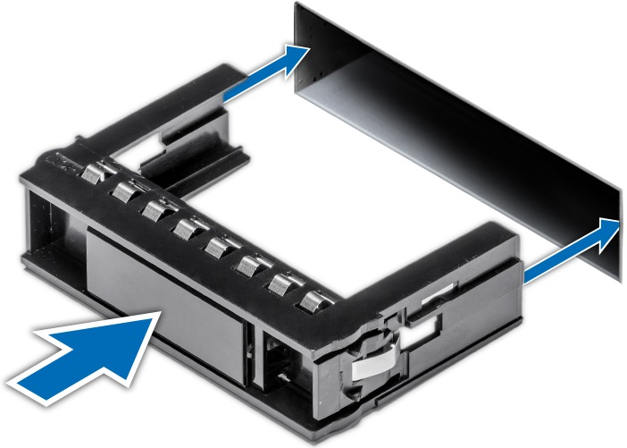
Smart-1 5150 lets you install additional disks. This section shows how to remove and install disk blanks that cover the empty disk slots.
To remove a disk blank on Smart-1 5150:
To install a disk blank on Smart-1 5150:
Important - If you are not replacing the failed disk immediately, then to maintain proper system cooling, install a disk blank in the empty disk slot. You can also remove the disk from the disk carrier and install the empty disk carrier into its disk slot.
Item |
Indicator |
Icon |
Description |
|---|---|---|---|
1 |
Status LED indicators |
N/A |
Indicate the status of the system. For more information, see Status LED Indicators. |
2 |
System notification LED indicator |
Indicates the system health. For more information, see System Notification LED Indicator. Note that the button is not supported. |
The status LED indicators are always off and only turns on to a solid amber if any error occurs.
Icon |
Description |
Condition |
|---|---|---|
|
Drive indicator |
The indicator turns solid amber if there is a drive error. |
|
Temperature indicator |
The indicator turns solid amber if the system experiences a thermal error (for example, the ambient temperature is out of range or there is a fan failure). |
|
Electrical indicator |
The indicator turns solid amber if the system experiences an electrical error (for example, voltage out of range, or a failed power supply unit (PSU) or voltage regulator). |
|
Memory indicator |
The indicator turns solid amber if a memory error occurs. |
|
PCIe indicator |
The indicator turns solid amber if a PCIe card experiences an error. |
The system notification indicator is located on the left control panel of your system. The LED is functioning and descriptions are in the table below. The button is not supported.
System Notification LED Indicator Code |
Condition |
|---|---|
Off |
Indicates that the appliance is turned on and the system is healthy. |
Blinking amber |
Indicates that the system is experiencing a fault. Check the System Event Log, see the |
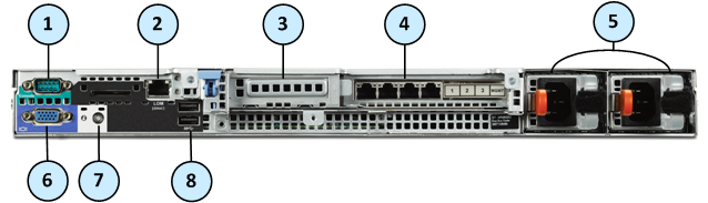
Item |
Component |
Description |
|---|---|---|
1 |
Serial console port |
Enables you to connect a serial device to the appliance. |
2 |
LOM (iDRAC) |
Enables LOM (iDRAC) management. For more information, see sk122914. |
3 |
PCIe expansion slot |
The expansion slot enables you to connect a PCI Express expansion card. For more information on the expansion cards that are supported on your appliance, see Smart-1 525/5050/5150 Installing and Removing Expansion Line Cards. |
4 |
Integrated network card |
4 Ethernet ports:
|
5 |
Power supply units |
For more information about the PSU configurations, see Smart-1 525/5050/5150 Installing and Removing AC Power Supply Units and Smart-1 525/5050/5150 Installing and Removing DC Power Supply Units. |
6 |
VGA port |
Enables you to connect a display device to the appliance. |
7 |
System notification LED |
Off - Indicates that the appliance is turned on and the system is healthy. Blinking amber - Indicates that the system is experiencing a fault. Check the System Event Log, see the |
8 |
USB 2.0 ports |
The USB ports are 9-pin and USB 2.0 compliant. These ports enable you to connect USB devices to the appliance. |
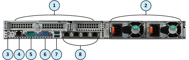
Item |
Component |
Description |
|---|---|---|
1 |
PCIe expansion slots |
The expansion slots enable you to connect PCI Express expansion cards. For more information on the expansion cards that are supported on your appliance, see Smart-1 525/5050/5150 Installing and Removing Expansion Line Cards. |
2 |
Power supply units |
For more information about the PSU configurations, see Smart-1 525/5050/5150 Installing and Removing AC Power Supply Units and Smart-1 525/5050/5150 Installing and Removing DC Power Supply Units. |
3 |
System notification LED |
Off - Indicates that the appliance is turned on and the system is healthy. Blinking amber - Indicates that the system is experiencing a fault. Check the System Event Log, see the |
4 |
LOM (iDRAC) |
Enables LOM (iDRAC) management. For more information, see sk122914. |
5 |
Serial console port |
Enables you to connect a serial device to the appliance. |
6 |
VGA port |
Enables you to connect a display device to the appliance. |
7 |
USB 3.0 ports |
The USB ports are 9-pin and USB 3.0 compliant. These ports enable you to connect USB devices to the appliance. |
8 |
Onboard network ports |
4 Ethernet ports:
|
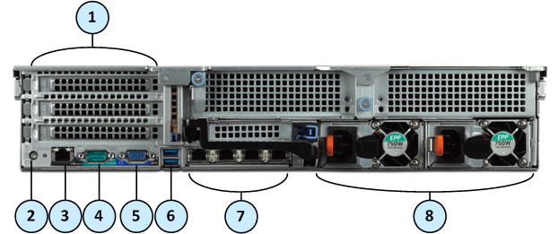
Item |
Component |
Description |
|---|---|---|
1 |
PCIe expansion slots |
The expansion slots enable you to connect PCI Express expansion cards. For more information on the expansion cards that are supported on your appliance, see Smart-1 525/5050/5150 Installing and Removing Expansion Line Cards. |
2 |
System notification LED |
Off - Indicates that the appliance is turned on and the system is healthy. Blinking amber - Indicates that the system is experiencing a fault. Check the System Event Log, see the |
3 |
LOM (iDRAC) |
Enables LOM (iDRAC) management. For more information, see sk122914. |
4 |
Serial console port |
Enables you to connect a serial device to the appliance. |
5 |
VGA port |
Enables you to connect a display device to the appliance. |
6 |
USB 3.0 ports |
The USB ports are 9-pin and USB 3.0 compliant. These ports enable you to connect USB devices to the appliance. |
7 |
Onboard network ports |
4 Ethernet ports:
|
8 |
Power Supply Units |
For more information about the PSU configurations, see Smart-1 525/5050/5150 Installing and Removing AC Power Supply Units and Smart-1 525/5050/5150 Installing and Removing DC Power Supply Units. |
The NIC on the back panel has LED indicators that provide information about the network activity and link status.
Item |
Component |
Description |
|---|---|---|
1 |
Link LED |
Off - Link off: No connectivity or the port is turned off. Steady green - Link on: 1Gbit/s data rate is selected. Steady amber - Link on: 100Mbit/s data rate is selected. Steady amber - Link on: 10Mbit/s data rate is selected. |
2 |
Activity LED |
Off - Link off: No connectivity, the port is turned off, or link is on without traffic. Blinking green - Link is on with traffic. |
The line card has LED indicators that provide information about the network activity and link status.
2 x 10GbE Expansion Line Cards
Item |
Component |
Description |
|---|---|---|
1 |
Link LED |
Off - Link off: No connectivity or the port is turned off. Steady green - Link on: 10Gbit/s data rate is selected. Steady amber - Link on: 1Gbit/s data rate is selected. |
2 |
Activity LED |
Off - Link off: No connectivity, the port is turned off, or link is on without traffic. Blinking green - Link is on with traffic. |
2 x 1GbE Expansion Line Cards
Item |
Component |
Description |
|---|---|---|
1 |
Link LED |
Off - Link off: No connectivity or the port is turned off. Steady amber - Link on: 1Gbit/s data rate is selected. |
2 |
Activity LED |
Off – Link off: No connectivity, the port is turned off, or link is on without traffic. Blinking green - Link is on with traffic. |
The Smart-1 Appliances has parts that you can easily replace to minimize downtime. There are also components that you can install to upgrade the appliance. These are the parts and components that can be used with the appliance:
For more information about installing these parts and components, see the Smart-1 525, 5050 and 5150 Appliances Home Page.
Unless directed to do so by Check Point technical support, you are prohibited by warranty and support agreements from replacing any parts.


