


|
|
|
In This Section: |
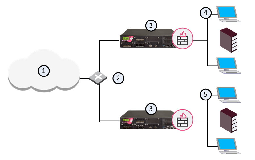
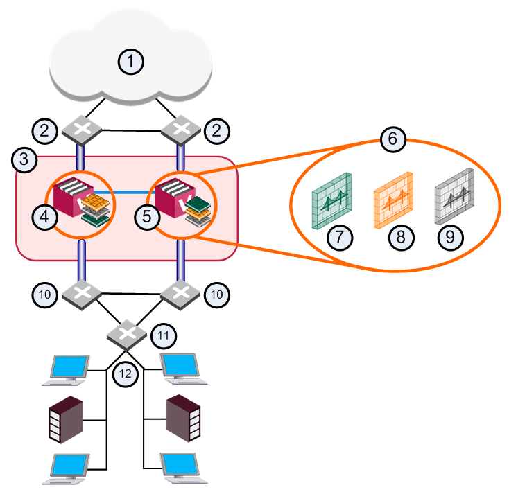
In large physical network deployments, multiple Check Point security products, such as Security Gateways, are deployed to protect network segments.
Item |
Description |
|---|---|
1 |
Internet |
2 |
Router |
3 |
Security Gateways |
4 |
Network 1 |
5 |
Network 2 |
Each Security Gateway physically connects to its own internal protected network and to a router for access to other internal networks and the Internet.
In a VSX environment, Virtual Systems protect internal networks. This section shows sample VSX deployments with Virtual Systems to protect internal networks.
Each example highlights different VSX features. In a real-world deployment, you can combine features to create a powerful cyber security solution for complex enterprise environments.
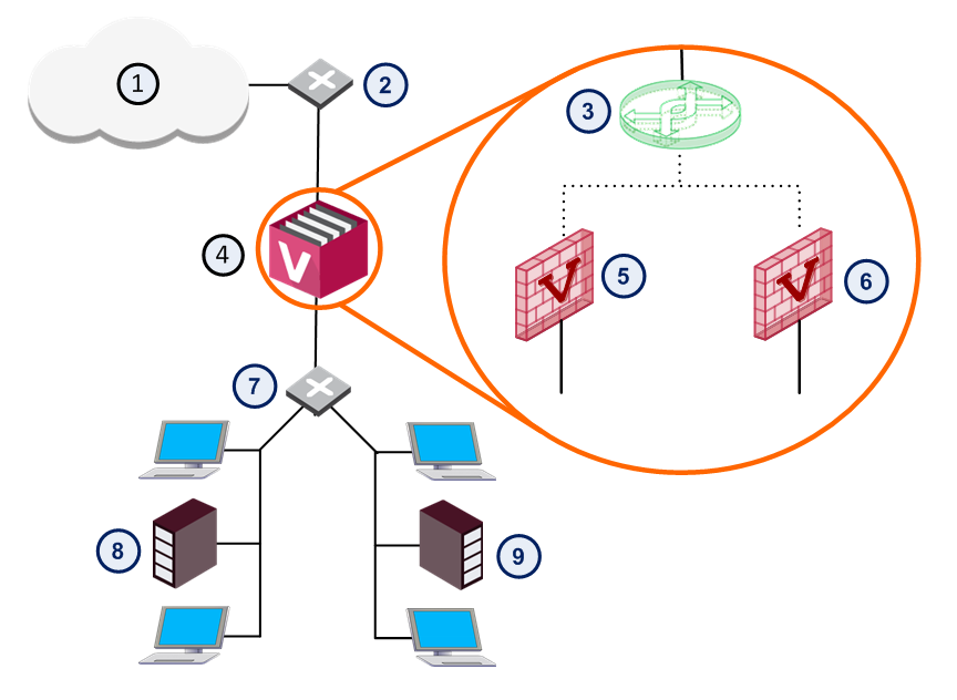
In a basic VSX configuration, Virtual Systems connect directly to protected internal networks through physical interfaces on the VSX Gateway. A Virtual Switch connects between internal networks, and to the Internet. This deployment is suitable for protecting a small, fixed quantity of internal networks.
The main disadvantage of this deployment is that each protected network requires its own dedicated physical interface on the VSX Gateway. Obviously, this deployment is not suitable for networks that require many Virtual Systems.
Item |
Description |
|
Item |
Description |
|---|---|---|---|---|
1 |
Internet |
|
6 |
Virtual System 2 |
2 |
Router |
|
7 |
Switch |
3 |
Virtual Switch |
|
8 |
Network 1 |
4 |
VSX Gateway |
|
9 |
Network 2 |
5 |
Virtual System 1 |
|
|
Warp Link |
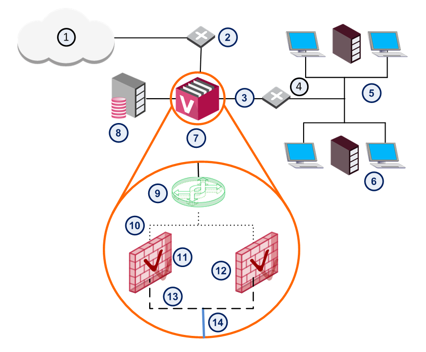
In this deployment example, Virtual Systems connect to internal protected networks through VLAN interfaces. The VSX Gateway connects to a VLAN switch with an 802.1q VLAN trunk, which is an aggregate of all VLANs passing through it.
This deployment option is appropriate for environments where many Virtual Systems protect many internal networks with one VSX Gateway or cluster. VLANs provide scalability and granularity, to provision more Virtual Systems and protected networks quickly, without changing the existing IP address structure.
Item |
Description |
|
Item |
Description |
|---|---|---|---|---|
1 |
Internet |
|
8 |
Management Server |
2 |
Router |
|
9 |
Virtual Switch |
3 |
Physical interface |
|
10 |
Warp interface |
4 |
VLAN Switch |
|
11 |
Virtual System 1 |
5 |
Network 1 |
|
12 |
Virtual System 2 |
6 |
Network 2 |
|
13 |
VLAN Interface |
7 |
VSX Gateway |
|
14 |
VLAN Trunk |
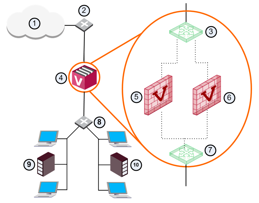
This deployment scenario enables Virtual Systems to connect to protected networks using a single physical interface without VLAN technology. The Virtual Router uses source-based routing rules to forward traffic to the appropriate Virtual System based on its source IP address.
In a VSX deployment with each Virtual System connected to a single Virtual Router: You can configure the Virtual Router to use source-based routing rules, to forward traffic to the appropriate Virtual System, based on the source IP address.
Item |
Description |
|
Item |
Description |
|---|---|---|---|---|
1 |
Internet |
|
7 |
Virtual Router |
2 |
Router |
|
8 |
Router |
3 |
Virtual Switch |
|
9 |
Network 1 |
4 |
VSX Gateway |
|
10 |
Network 2 |
5 |
VS 1 |
|
|
Warp link |
6 |
VS 2 |
|
|
|
Notes to this scenario:
The Routing Concept section provides a detailed discussion of routing options in VSX environments.
A Virtual System in bridge mode implements native layer-2 bridging instead of IP routing and can co-exist with layer-3 Virtual Systems on the same VSX Gateway. This allows network administrators to easily and transparently deploy a Virtual System in an existing network topology without reconfiguring the existing IP routing scheme.
Bridge Mode deployments are particularly suitable for large-scale clustered environments.
The Active/Standby Bridge Mode provides path redundancy and loop prevention, while offering seamless support for Virtual System Load Sharing and overcoming many Spanning Tree Protocol (STP) Bridge mode limitations.
In this scenario, each individual member connects to pair of redundant switches via a VLAN trunk. All Virtual Systems in a given member share the same VLAN trunk.
Item |
Description |
|
Item |
Description |
|---|---|---|---|---|
1 |
Internet |
|
9 |
VS 3 Backup |
2 |
Redundant switches (external) |
|
10 |
Redundant switches (internal) |
3 |
VSX Cluster |
|
11 |
VLAN Switch |
4 |
Member 1 |
|
12 |
Internal Networks |
5 |
Member 2 |
|
|
Sync Network |
6 |
Virtual Systems in Bridge Mode |
|
|
Physical Interface |
7 |
VS 1 Active |
|
|
VLAN Trunk |
8 |
VS 2 Standby |
|
|
|
When using the Active/Standby Bridge Mode in a High Availability deployment, VSX directs traffic to VSX Cluster Members according to predefined priorities and state of VSX Cluster Members. In VSLS deployments, VSX distributes the traffic load amongst VSX Cluster Members according to a set of predefined preferences.
This deployment scenario is appropriate for very large enterprises.
A three layer hierarchical model is appropriate for large, high-traffic network environments. It contains a mixture of components as described below:
Use Active/Standby Bridge Mode with VSX to enforce the security policy over the distribution layer. 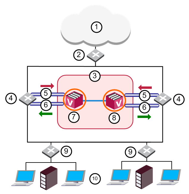
Item |
Description |
|
Item |
Description |
|---|---|---|---|---|
1 |
Internet |
|
8 |
Member 2 |
2 |
Core Network Backbone switch |
|
9 |
LAN switches |
3 |
VSX Cluster |
|
10 |
Internal Networks |
4 |
Router |
|
|
Sync Network |
5 |
VLAN 10 |
|
|
Physical Interface |
6 |
VLAN 20 |
|
|
VLAN Trunk |
7 |
Member 1 |
|
|
|
The routers direct external, "dirty" traffic (typically from the Internet) to the appropriate Virtual System via a segregated VLAN. Filtered, "clean" traffic exits the Virtual System through a separate segregated VLAN back to the routers and on to internal destinations.
This deployment scenario is appropriate for very large enterprises.

