


|
|
|
By implementing native layer-2 bridging instead of IP routing, you can add Virtual Systems without adversely affecting the existing IP structure.
When in the Bridge mode, Virtual System interfaces do not require IP addresses. You can optionally assign an IP address to the Virtual System itself (not the interfaces) to enable layer-3 monitoring, which provides network fault detection functionality.
VSX supports these Bridge mode models:
The Spanning Tree Protocol is an industry standard technology to prevent loops in high-speed switched networks. To use the STP Bridge mode, you must have STP deployed and properly configured on your network. These STP layer-2 protocols are supported:
See your vendor documentation to learn how to deploy and configure STP on your network hardware.
The Active/Standby Bridge Mode enhances both:
Active/Standby Bridge Mode has these advantages:
The principal limitation of the Active/Standby Bridge Mode is that it breaks the STP tree structure.
|
Note - When configuring a Virtual System in the Active/Standby Bridge Mode, you should remove Virtual System VLANs from the STP database in the switches. This action prevents delays due to trunk interface failback. |
This section presents illustrative Active/Standby Bridge Mode deployments, which cannot function using a standard STP Bridge mode configuration.
In this deployment, each member connects to pair of redundant switches through a VLAN Trunk. All Virtual Systems in a given VSX Cluster Member share the same VLAN Trunk.
Item |
Description |
|
Item |
Description |
|---|---|---|---|---|
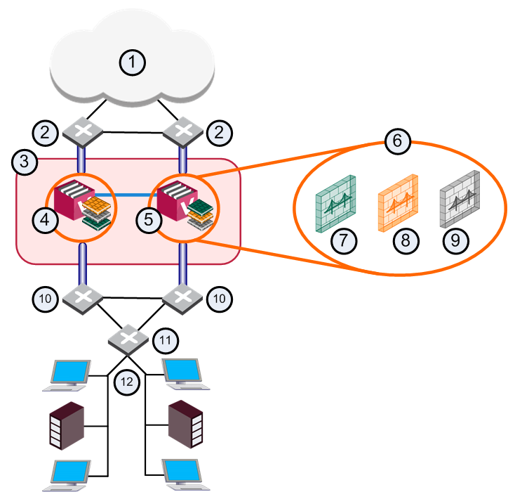
1 |
Internet |
|
9 |
Virtual System 3 is Backup |
2 |
Redundant switches (external) |
|
10 |
Redundant switches (internal) |
3 |
VSX Cluster |
|
11 |
VLAN Switch |
4 |
VSX Cluster Member 1 |
|
12 |
Internal Networks |
5 |
VSX Cluster Member 2 |
|
|
Sync Network |
6 |
Virtual Systems in Bridge Mode |
|
|
Physical Interface |
7 |
Virtual System 1 is Active |
|
|
VLAN Trunk |
8 |
Virtual System 2 is Standby |
|
|
|
With Active/Standby Bridge Mode in High Availability mode, VSX Cluster directs traffic to VSX Cluster Members according to administrator-defined priorities and status.
In Virtual System Load Sharing deployments, the system distributes the traffic load amongst VSX Cluster Members according to the Virtual System Load Sharing configuration.
A three-layer hierarchical model is used in large, high-traffic network environments.
VSX in Active/Standby Bridge Mode is incorporated in the distribution layer, enforcing the security policy.
The routers direct external traffic to the appropriate Virtual System through a segregated VLAN. Inspected traffic exits the Virtual System through a separate segregated VLAN, to the routers and then to internal destinations.

