


|
|
|
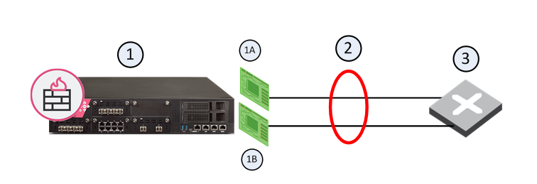
Check Point security devices support Link Aggregation, a technology that joins multiple physical interfaces into one virtual interface, known as a bond interface. The bond interface share the load among many interfaces, which gives fault tolerance and increases throughput. Check Point devices support the IEEE 802.3ad Link Aggregation Control Protocol (LACP) for dynamic link aggregation.
Item No. |
Description |
|---|---|
1 |
Security Gateway |
1A |
Interface 1 |
1B |
interface 2 |
2 |
Bond Interface |
3 |
Router |
A bond interface (also known as a bonding group or bond) is identified by its Bond ID (for example: bond1) and is assigned an IP address. The physical interfaces included in the bond are called slaves and do not have IP addresses.
You can define a bond interface to use one of these functional strategies:
Note - Bonding Load Sharing mode requires SecureXL to be enabled on Security Gateway or each Cluster Member.
You can configure Bond Load Sharing to use one of these modes:
For Bonding High Availability mode and for Bonding Load Sharing mode:
To configure a bond interface:
Step |
Description |
|---|---|
1 |
In the navigation tree, click Network Management > Network Interfaces. |
2 |
Make sure that the slave interfaces, which you wish to add to the Bond interface, do not have IP addresses. |
3 |
For a new bond interface, select Add > Bond. To edit an existing Bond interface, select the Bond interface and click Edit. |
4 |
On the IPv4 tab, enter the IPv4 address and subnet mask. You can optionally select the Obtain IPv4 Address automatically option. |
5 |
On the IPv6 tab (optional), enter the IPv6 address and mask length. You can optionally select the Obtain IPv6 Address automatically option. Important - First, you must enable the IPv6 Support and reboot. |
6 |
On the Bond tab:
|
7 |
On the Advanced tab:
|
8 |
Additional configuration settings are available depending on the selected Bond Operation Mode:
|
9 |
Click OK. |
In the CLI, bond interfaces are known as bonding groups.
Important: After you run a Gaia Clish command to add, configure, or delete an object, run the save config command to save the settings permanently.
To create a bond interface in the Gaia Clish:
Step |
Description |
|---|---|
1 |
Make sure that the slave interfaces do not have IP addresses. |
2 |
|
3 |
Define the slave interfaces and set them to the UP state. |
4 |
|
5 |
Define other bond parameters: primary interface, media monitoring, and delay rate. |
This is a quick reference for Link Aggregation commands. Use these commands to configure Link Aggregation.
Note - You configure an IP address on a Bonding Group in the same way as you do on a physical interface.
Syntax
add bonding group <Bond Group ID> |
add bonding group <Bond Group ID> interface <Name of Slave Interface> |
Note - Make sure that the slave interfaces, which you wish to add to the Bonding Group, do not have IP addresses.
set bonding group <Bond Group ID> mode active-backup [primary <Name of Slave Interface>] mode round-robin mode 8023AD [lacp-rate {slow | fast}] mode xor xmit-hash-policy {layer2 | layer3+4} [up-delay <0-5000>] [down-delay <0-5000>] [monitoring-type {arp <options> | mii <options>}] |
show bonding {group <Bond Group ID> | groups} |
delete bonding group <Bond Group ID> [interface <Interface Name> | force-ignore-routes] |
delete bonding group <Bond Group ID> interface <Name of Slave Interface 1> delete bonding group <Bond Group ID> interface <Name of Slave Interface ...> delete bonding group <Bond Group ID> interface <Name of Slave Interface N> delete bonding group <Bond Group ID> |
Important - After you add, configure, or delete features, run the save config command to save the settings permanently.
Parameters
Parameter |
Description |
|---|---|
<Bond Group ID> |
Configures the Bond Group ID.
|
<Name of Slave Interface> |
Specifies the name of the slave physical interface, which you add to (or remove from) the bond group. Make sure that the slave interfaces do not have any IP addresses or aliases configured. |
|
Configures the Bond operating mode:
|
|
Specifies the name of the primary slave interface in the bond. The first slave interface added to the bond group, becomes the primary. Note - Applies only to the active-backup bond mode. |
|
Specifies the time in milliseconds to wait before enabling a slave after link recovery was detected.
|
|
Specifies the time in milliseconds to wait before disabling a slave after link failure was detected.
|
|
Specifies the Link Aggregation Control Protocol packet transmission rate:
Note - Applies only to the 802.3AD bond mode. |
|
Specifies the Bond monitoring type:
|
|
Specifies the algorithm to use for assigning the traffic to Active slave interfaces:
Note - Applies only to the XOR bond mode. |
Example 1 - Active-Backup mode with default settings
gaia> add bonding group 1
gaia> add bonding group 1 interface eth2
gaia> add bonding group 1 interface eth3
gaia> set bonding group 1 mode active-backup primary eth2
gaia> show bonding group 1 Bond Configuration xmit-hash-policy Not configured down-delay 200 primary eth2 monitoring-type Not configured arp-target-ip Not configured lacp-rate Not configured mode active-backup up-delay 200 mii-interval 100 Bond Interfaces eth2 eth3 gaia> |
Example 2 - XOR mode with default settings
gaia> add bonding group 1
gaia> add bonding group 1 interface eth2
gaia> add bonding group 1 interface eth3
gaia> set bonding group 1 mode xor xmit-hash-policy layer3+4
gaia> show bonding group 1 Bond Configuration xmit-hash-policy layer3+4 down-delay 200 primary Not configured monitoring-type Not configured arp-target-ip Not configured lacp-rate Not configured mode xor up-delay 200 mii-interval 100 Bond Interfaces eth2 eth3 gaia> |
Example 3 - XOR mode with monitoring type 'mii'
gaia> add bonding group 1
gaia> add bonding group 1 interface eth2
gaia> add bonding group 1 interface eth3
gaia> set bonding group 1 mode xor xmit-hash-policy layer3+4
gaia> set bonding group 1 monitoring-type mii mii-interval 50
gaia> show bonding group 1 Bond Configuration xmit-hash-policy layer3+4 down-delay 100 primary Not configured monitoring-type mii arp-target-ip 0 lacp-rate Not configured mode xor up-delay 100 mii-interval 50 Bond Interfaces eth2 eth3 gaia> |
Example 4 - XOR mode with monitoring type 'arp'
gaia> add bonding group 1
gaia> add bonding group 1 interface eth2
gaia> add bonding group 1 interface eth3
gaia> set bonding group 1 mode xor xmit-hash-policy layer3+4
gaia> set bonding group 1 monitoring-type arp arp-target-ip 192.168.1.1
gaia> show bonding group 1 Bond Configuration xmit-hash-policy layer3+4 down-delay 0 primary Not configured monitoring-type arp arp-target-ip 192.168.1.1 lacp-rate Not configured mode xor up-delay 0 mii-interval 0 Bond Interfaces eth2 eth3 gaia> |
Syntax
|
Example
gaia> add bonding group 777 |
Note - Do not change the state of bond interface manually using the set interface <Bond ID> state command. This is done automatically by the bonding driver.
Syntax
add bonding group <Bond Group ID> interface <Name of Slave Interface> |
Example
gaia> add bonding group 777 interface eth4 gaia> |
Notes:
Syntax
delete bonding group <Bond Group ID> interface <Name of Slave Interface> |
Example
gaia> delete bonding group 777 interface eth4 |
Note - You must delete all non-primary slave interfaces before you remove the primary slave interface.
Syntax
delete bonding group <Bond Group ID> |
Example
gaia> delete bonding group 777 |
Notes:
set interface bondID state command. This is done automatically by the bonding driver.Bond operating mode specifies how slave interfaces are used in a bond interface.
Syntax
set bonding group <Bond Group ID> mode round-robin active-backup [primary <Name of Slave Interface>] xor xmit-hash-policy {layer2 | layer3+4} 8023AD [lacp-rate {slow | fast}] |
Example
|
Notes:
You can configure the monitoring of the slave interfaces for link-failure.
Syntax
set bonding group <Bridge Group ID> monitoring-type arp arp-target-ip <IPv4 Address> mii mii-interval<0-5000> |
Example
gaia> set bonding group 1 monitoring-type arp arp-target-ip 192.168.1.1 gaia> set bonding group 1 monitoring-type mii mii-interval 50 |
Note - The default mii-interval value is 100 ms.
The Up-Delay specifies show much time in milliseconds to wait before enabling a slave after link recovery was detected.
Syntax
set bonding group <Bond Group ID> up-delay <0-5000> |
Example
gaia> set bonding group 1 up-delay 100 |
Note - The default up-interval value is 200 ms.
The Down-Delay specifies how much time in milliseconds to wait before disabling a slave after link failure was detected
Syntax
set bonding group <Bond Group ID> down-delay <0-5000> |
Example
gaia> set bonding group 1 down-delay 100 |
Note - The default down-interval value is 200 ms.
To make sure that a Bond interface is working, run this command in Expert mode:
[Expert@Gaia:0]# cat /proc/net/bonding/<Bond Group ID> |
Example output for Round Robin mode:
[Expert@Gaia:0]# cat /proc/net/bonding/bond1 Ethernet Channel Bonding Driver: v3.2.4 (January 28, 2008)
Bonding Mode: load balancing (round-robin) MII Status: up MII Polling Interval (ms): 100 Up Delay (ms): 200 Down Delay (ms): 200
Slave Interface: eth2 MII Status: up Link Failure Count: 0 Permanent HW addr: 00:50:56:a3:73:69
Slave Interface: eth3 MII Status: up Link Failure Count: 0 Permanent HW addr: 00:50:56:a3:73:70 [Expert@Gaia:0]# |
Example output for Active-Backup mode:
[Expert@Gaia:0]# cat /proc/net/bonding/bond1 Ethernet Channel Bonding Driver: v3.2.4 (January 28, 2008)
Bonding Mode: fault-tolerance (active-backup) Primary Slave: eth2 Currently Active Slave: eth2 MII Status: up MII Polling Interval (ms): 100 Up Delay (ms): 200 Down Delay (ms): 200
Slave Interface: eth2 MII Status: up Link Failure Count: 0 Permanent HW addr: 00:50:56:a3:73:69
Slave Interface: eth3 MII Status: up Link Failure Count: 0 Permanent HW addr: 00:50:56:a3:73:70 [Expert@Gaia:0]# |
Example output for XOR mode:
[Expert@Gaia:0]# cat /proc/net/bonding/bond1 Ethernet Channel Bonding Driver: v3.2.4 (January 28, 2008)
Bonding Mode: load balancing (xor) Transmit Hash Policy: layer2 (0) MII Status: up MII Polling Interval (ms): 100 Up Delay (ms): 200 Down Delay (ms): 200
Slave Interface: eth2 MII Status: up Link Failure Count: 0 Permanent HW addr: 00:50:56:a3:73:69
Slave Interface: eth3 MII Status: up Link Failure Count: 0 Permanent HW addr: 00:50:56:a3:73:70 [Expert@Gaia:0]# |
Example output for 802.3ad mode:
[Expert@Gaia:0]# cat /proc/net/bonding/bond1 Ethernet Channel Bonding Driver: v3.2.4 (January 28, 2008)
Bonding Mode: IEEE 802.3ad Dynamic link aggregation Transmit Hash Policy: layer2 (0) MII Status: up MII Polling Interval (ms): 100 Up Delay (ms): 200 Down Delay (ms): 200
802.3ad info LACP rate: slow
Slave Interface: eth2 MII Status: up Link Failure Count: 0 Permanent HW addr: 00:50:56:a3:73:69 Aggregator ID: 1
Slave Interface: eth3 MII Status: up Link Failure Count: 0 Permanent HW addr: 00:50:56:a3:73:70 Aggregator ID: 1 [Expert@Gaia:0]# |

