


|
|
|
In This Section: |
Network Objects, defined in SmartConsole and stored in the proprietary Check Point object database, represent physical and virtual network components (such as gateways, servers, and users), and logical components (such as IP address ranges and Dynamic Objects). Before you create Network Objects, analyze the needs of your organization:
Objects in SmartConsole represent networks, devices, protocols and resources. SmartConsole divides objects into these categories:
Icon |
Object Type |
Examples |
|---|---|---|
|
Network Objects |
Gateways, hosts, networks, address ranges, dynamic objects, security zones |
|
Services |
Services, Service groups |
|
Custom Applications/Sites |
Applications, Categories, Mobile applications |
|
VPN Communities |
Site to Site or Remote Access communities |
|
Users |
Users, user groups, and user templates |
|
Data Types |
International Bank Account Number - IBAN, HIPAA - Medical Record Number - MRN, Source Code. |
|
Servers |
Trusted Certificate Authorities, RADIUS, TACACS |
|
Time Objects |
Time, Time groups |
|
UserCheck Interactions |
Message windows: Ask, Cancel, Certificate Template, Inform, and Drop |
|
Limit |
Download and upload bandwidth |
You can add, edit, delete, and clone objects. A clone is a copy of the original object, with a different name. You can also replace one object in the Policy with another object.
Note - Do not create two objects with the same name. You will see a validation error when you try to publish. To resolve, change one of the object names.
To work with objects, right-click the object in the object tree or in the Object Explorer, and select the action.
You can delete objects that are not used, and you can find out where an object is used.
To clone an object:
The Clone Object window opens.
To find out where an object is used:
In the object tree or in the Object Explorer, right-click the object and select Where Used.
To replace an object with a different object:
To delete all instances of an object:
Object tags are keywords or labels that you can assign to the network objects or groups of objects for search purposes. These are the types of tags you can assign:
Each tag has a name and a value. The value can be static, or dynamically filled by detection engines.
To add a tag to an object:
The new tag shows to the right of the Add Tag field.
In This Section: |
A Network is a group of IP addresses defined by a network address and a net mask. The net mask indicates the size of the network.
A Broadcast IP address is an IP address which is destined for all hosts on the specified network. If this address is included, the Broadcast IP address will be considered as part of the network.
A network group is a collection of hosts, gateways, networks or other groups.
Groups are used where you cannot work with single objects, e.g. when working with VPN domains or with topology definitions.
Groups facilitate and simplify network management. Modifications are applied to the group instead of each member of the group.
To create a group of network objects:
The New Network Group window opens.
A Check Point Host can have multiple interfaces but no routing takes place. It is an endpoint that receives traffic for itself through its interfaces. (In comparison, a Security Gateway routes traffic between its multiple interfaces.) For example, if you have two unconnected networks that share a common Security Management Server and Log Server, configure the common server as a Check Point Host object.
A Check Point Host has one or more Software Blades installed. But if the Firewall blade is installed on the Check Point Host, it cannot function as a firewall. The Host requires SIC and other features provided by the actual firewall.
A Check Point Host has no routing mechanism, is not capable of IP forwarding, and cannot be used to implement Anti-spoofing. If the host must do any of these, convert it to be a Security Gateway.
The Security Management Server object is a Check Point Host.
Note - When you upgrade to R80.10 from R77.30 or earlier versions, Node objects are converted to Host objects.
A gateway cluster is a group of Security Gateways with Cluster software installed: ClusterXL, or another Clustering solution. Clustered gateways add redundancy through High Availability or Load Sharing.
An address range is a range of IP addresses on the network, defined by the lowest and the highest IP addresses. Use an Address Range object when you cannot define a range of IP addresses by a network IP and a net mask. The Address Range objects are also necessary for the implementation of NAT and VPN.
A Domain object lets you define a host or DNS domain by its name only. It is not necessary to have the IP address of the site.
You can use the Domain object in the source and destination columns of an Access Control Policy.
You can configure a Domain object in two ways:
In the object name, use the Fully Qualified Domain Name (FQDN). Use the format .x.y.z (with a dot "." before the FQDN). For example, if you use .www.example.com then the Gateway matches www.example.com
This option is supported for R80.10 and higher, and is the default. It is more accurate and faster than the non-FQDN option.
The Security Gateway looks up the FQDN with a direct DNS query, and uses the result in the Rule Base.
This option supports SecureXL Accept templates. Using domain objects with this option in a rule has no effect on the performance of the rule, or of the rules that come after it.
This option enforces the domain and its sub-domains. In the object name, use the format .x.y for the name. For example, use .example.com or .example.co.uk for the name. If you use .example.com, then the Gateway matches www.example.com and support.example.com
The Gateway does the name resolution using DNS reverse lookups, which can be inaccurate. The Gateway uses the result in the Rule Base, and caches the result to use again.
When upgrading from R77, this option is enforced.
A dynamic object is a "logical" object where the IP address is resolved differently for each Security Gateway, using the dynamic_objects command.
For R80.10 Security Gateways and higher, dynamic objects support SecureXL Accept templates. Therefore, there is no performance impact on a rule that uses a dynamic object, or on rules that come after it.
Dynamic Objects are predefined for LocalMachine-all-interfaces. The DAIP computer interfaces (static and dynamic) are resolved into this object.
Security Zones let you to create a strong Access Control Policy that controls the traffic between parts of the network.
A Security Zone object represents a part of the network (for example, the internal network or the external network). You assign a network interface of a Security Gateway to a Security Zone. You can then use the Security Zone objects in the Source and Destination columns of the Rule Base.
Use Security Zones to:
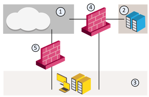
For example, in the diagram, we have three Security Zones for a typical network: ExternalZone (1), DMZZone (2) and InternalZone (3).
A Security Gateway interface can belong to only one Security Zone. Interfaces to different networks can be in the same Security Zone.
Workflow
Source |
Destination |
VPN |
Service |
Action |
|
|---|---|---|---|---|---|
InternalZone |
ExternalZone |
Any Traffic |
Any |
Accept |
|
Before you can use Security Zones in the Rule Base, you must assign Gateway interfaces to Security Zones.
To create a Security Zone:
The Security Zone window opens.
To assign an interface to a Security Zone
The Gateway Properties window opens.
The Interface window opens. The Topology area of the General pane shows the Security Zone to which the interface is already bound. By default, the Security Zone is calculated according to where the interface Leads To.
The Topology Settings window opens.
Or click New to create a new one.
These are the predefined security zones, and their intended purposes:
A DMZ lets external users and applications access specific internal servers, but prevents the external users accessing secure company networks. Add rules to the firewall Rule Base that allow traffic to the company DMZ. For example, a rule that allows HTTP and HTTPs traffic to your web server in the DMZ.
An Externally Managed Security Gateway or a Host is a gateway or a Host which has Check Point software installed on it. This Externally Managed gateway is managed by an external Security Management Server. While it does not receive the Check Point Security Policy, it can participate in Check Point VPN communities and solutions.
An Interoperable Device is a device that has no Check Point Software Blades installed. The Interoperable Device:
There are five types of VoIP Domain objects:
In many VoIP networks, the control signals follow a different route through the network than the media. This is the case when the call is managed by a signal routing device. Signal routing is done in SIP by the Redirect Server, Registrar, and/or Proxy. In SIP, signal routing is done by the Gatekeeper and/or gateway.
Enforcing signal routing locations is an important aspect of VoIP security. It is possible to specify the endpoints that the signal routing device is allowed to manage. This set of locations is called a VoIP Domain. For more information refer to the R80.10 VoIP Administration Guide.
A Logical Server is a group of machines that provides the same services. The workload of this group is distributed between all its members.
When a Server group is stipulated in the Servers group field, the client is bound to this physical server. In Persistent server mode the client and the physical server are bound for the duration of the session.
The load balancing algorithm stipulates how the traffic is balanced between the servers. There are several types of balancing methods:
The Open Security Extension features let you manage third-party devices with the Check Point SmartConsole. The number of managed devices, both hardware and software packets, depends on your license. OSE devices commonly include hardware security devices for routing or dedicated Network Address Translation and Authentication appliances. Security devices are managed in the Security Policy as Embedded Devices.
The Security Management Server generates Access Lists from the Security Policy and downloads them to selected routers and open security device. Check Point supports these devices:
OSE Device |
Supported Versions |
|---|---|
Cisco Systems |
9.x, 10.x, 11.x, 12.x |
The Check Point Rule Base must not have these objects. If it does, the Security Management Server will not generate Access Lists.
OSE devices report their network interfaces and setup at boot time. Each OSE device has a different command to list its configuration. You must define at least one interface for each device, or Install Policy will fail.
To define an OSE Device:
We recommend that you also add the OSE device to the host lists on other servers: hosts (Linus) and lmhosts (Windows).
You can enable Anti-Spoofing on the external interfaces of the device. Double-click the interface. In the Interface Properties window > Topology tab, select External and Perform Anti-Spoofing.
For Cisco (Version 10.x and higher) devices, you must specify the direction of the filter rules generated from anti-spoofing parameters. The direction of enforcement is specified in the Setup tab of each router.
For Cisco routers, the direction of enforcement is defined by the Spoof Rules Interface Direction property.
Access List No — The number of Cisco access lists enforced. Cisco routers Version 12x and below support an ACL number range from 101-200. Cisco routers Version 12x and above support an ACL range number from 101-200 and also an ACL number range from 2000-2699. Inputting this ACL number range enables the support of more interfaces.
For each credential, select an option:
Username — The name required to logon to the OSE device.
Password — The Administrator password (Read only) as defined on the router.
Enable Username — The user name required to install Access Lists.
Enable Password — The password required to install Access Lists.
Version — The Cisco OSE device version (9.x, 10.x, 11.x, 12.x).
OSE Device Interface Direction — Installed rules are enforced on data packets traveling in this direction on all interfaces.
Spoof Rules Interface Direction — The spoof tracking rules are enforced on data packets traveling in this direction on all interfaces.


