


In This Section: |
While there are a few connectivity issues regarding VPN between Security Gateways, remote access clients present a special challenge. Remote clients are, by their nature, mobile. During the morning they may be located within the network of a partner company, the following evening connected to a hotel LAN or behind some type of enforcement or NATing device. Under these conditions, a number of connectivity issues can arise:
Check Point resolves NAT related connectivity issues with a number of features:
Check Point resolves port filtering issues with Visitor Mode (formally: TCP Tunneling).
Other connectivity issues can arise, for example when a remote client receives an IP address that matches an IP on the internal network. Routing issues of this sort are resolved using Office mode. For more information see: Office Mode.
Other issues, such as Domain Name Resolution involving DNS servers found on an internal network protected by a Security Gateway, are resolved with Split DNS. For more information on Split DNS see: Remote Access Advanced Configuration.
NAT related issues arise with hide NAT devices that do not support packet fragmentation.
When a remote access client attempts to create a VPN tunnel with its peer Security Gateway, the IKE or IPsec packets may be larger than the Maximum Transmission Unit (MTU) value. If the resulting packets are greater than the MTU, the packets are fragmented at the Data Link layer of the Operating System's TCP/IP stack.
Problems arise when the remote access client is behind a hide NAT device that does not support this kind of packet fragmentation:
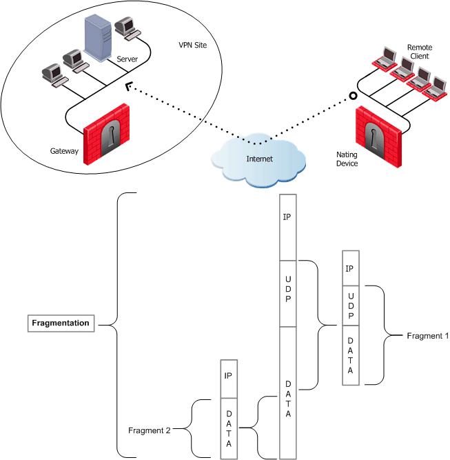
Hide NAT not only changes the IP header but also the port information contained in the UDP header. In Figure 31‑1, the UDP packet is too long so the remote client fragments the packet. The first fragment consists of the IP header plus the UDP header and some portion of the data. The second fragment consists of only the IP header and the second data fragment. The NATing device does not know how to wait for all the fragments, reassemble and NAT them.
When the first fragment arrives, the NAT device successfully translates the address information in the IP header, and port information in the UDP header and forwards the packet. When the second fragment arrives, the NATing device cannot translate the port information because the second packet does not contain a UDP header; the packet is dropped. The IKE negotiation fails.
To understand why large UDP packets arise, we need to take a closer look at the first phase of IKE. During IKE phase I, the remote access client and Security Gateway attempt to authenticate each other. One way of authenticating is through the use of certificates. If the certificate or Certificate Revocation List (CRL) is long, large UDP packets result, which are then fragmented by the operating system of the remote client.
|
Note - If the VPN peers authenticate each other using pre-shared secrets, large UDP packets are not created; however, certificates are more secure, and thus recommended. |
IKE over TCP solves the problem of large UDP packets created during IKE phase I. The IKE negotiation is performed using TCP packets. TCP packets are not fragmented; in the IP header of a TCP packet, the DF flag ("do not fragment") is turned on. A full TCP session is opened between the peers for the IKE negotiation during phase I.
A remote access client does not have a policy regarding methods of encryption and integrity. Remote access clients negotiate methods for encryption and integrity via a series of proposals, and need to negotiate all possible combinations with the Security Gateway. This can lead to large UDP packets which are once again fragmented by the remote client's OS before sending. The NAT device in front of the remote client drops the packet that has no UDP header (containing port information). Again, the IKE negotiation fails.
Why not use IKE over TCP again, as in phase I?
IKE over TCP solves the fragmentation problem of long packets, but in phase II there are times when the Security Gateway needs to initiate the connection to the remote client. (Only the remote client initiates phase I, but either side can identify the need for a phase II renewal of keys; if the Security Gateway identifies the need, the Security Gateway initiates the connection.)
If the Security Gateway initiates the connection, the Security Gateway knows the IP address of the NATing device, but cannot supply a port number that translates to the remote client behind the NATing device. (The port number used during previous connections is only temporary, and can quickly change.) The NATing device cannot forward the connection correctly for the remote client; the connection initiated by the Security Gateway fails.
It is possible to use IKE over TCP, but this demands a TCP connection to be always open; the open session reserves the socket on the Security Gateway, taking up valuable system resources. The more reasonable solution is to keep open the port on the NATing device by sending UDP "keep alive" packets to the Security Gateway, and then performing IKE phase II in the usual way. However, there is still a need to shorten the UDP packets to prevent possible fragmentation.
Both Security Gateway and remote peer start the IKE negotiation by proposing a small number of methods for encryption and integrity. The more common methods are included in the small proposals.
If proposals match between the remote client and the Security Gateway, the proposed methods are used; if no match is found, a greater number of proposals are made. Usually a match is found with the small proposals, and fragmentation is no longer an issue. However, there are cases where a match is not found, and a larger number of proposals need to be made. (This will most likely happen in instances where the remote Security Gateway uses AES-128 for encryption, and AES-128 is not included in the small proposals.)
A greater number of proposals can result in larger UDP packets. These larger packets are once again fragmented at the Data Link Layer of the TCP/IP stack on the client, and then discarded by the hide NAT device that does not support fragmentation. In the case of AES-128, this method of encryption can be included in the small proposals by defining AES-128 as the preferred method.
Having successfully negotiated IKE phases I and II, we move into the IPsec stage. Data payloads encrypted with (for example) 3DES and hashed (for integrity) with MD5, are placed within an IPsec packet. However, this IPsec packet no longer contains a TCP or UDP header. A hide NAT device needs to translate the port information inside the header. The TCP/UDP header has been encrypted along with the data payload and can no longer be read by the NATing device.
A port number needs to be added; UDP Encapsulation is a process that adds a special UDP header that contains readable port information to the IPsec packet:
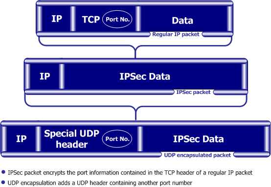
The new port information is not the same as the original. The port number 2746 is included in both the source and destination ports. The NAT device uses the source port for the hide operation but the destination address and port number remains the same. When the peer Security Gateway sees 2746 as the port number in the destination address, the Security Gateway calls a routine to decapsulate the packet.
IPsec Path MTU is a way of dealing with IPsec packet fragmentation. The Data Link layer imposes an upper limit on the size of the packets that can be sent across the physical network, the Maximum Transmission Unit, or MTU. Before sending a packet, the TCP/IP stack of the operating system queries the local interface to obtain its MTU. The IP layer of the TCP/IP stack compares the MTU of the local interface with the size of the packet and fragments the packet if necessary.
When a remote client is communicating across multiple routers with a Security Gateway, it is the smallest MTU of all the routers that is important; this is the path MTU (PMTU), and for remote access clients there is a special IPsec PMTU discovery mechanism to prevent the OS of the client from fragmenting the IPsec packet if the IPsec packet is too large.
However, the PMTU between the remote client and the Security Gateway will not remain constant, since routing across the Internet is dynamic. The route from Security Gateway to client may not be the same in both directions, hence each direction may have its own PMTU. VPN handles this in two ways:
After IKE phase II but before the IPsec stage, the remote access client sends special discovery IPsec packets of various sizes to the Security Gateway. The DF (do not fragment) bit on the packet is set. If a packet is longer than any router's MTU, the router drops the packet and sends an ICMP error message to the remote client. From the largest packet not fragmented, the remote client resolves an appropriate PMTU. This PMTU is not conveyed directly to the OS. Unknown to the operating system, during the TCP three-way handshake, the Maximum Segment Size (MSS) on the SYN and SYN-ACK packets are changed to reflect the PMTU. This is known as Active IPsec PMTU.
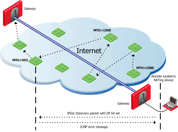
Passive IPsec PMTU solves the problem of dynamic Internet routing. Passive IPsec PTMU is a process that occurs when either side receives an ICMP error message resulting from a change in the routing path. Since routes change dynamically on the Internet, if a different router needs to fragment the packet that has the DF bit set, the router discards the packet and generates an ICMP "cannot fragment" error message. The error message is sent to the VPN peer that sent the packet. When the peer receives this error message, the peer decreases the PMTU and retransmits.
|
Note - From the system administrator perspective, there is nothing to configure for PMTU; the IPsec PMTU discovery mechanism, both active and passive, runs automatically. |
In the following figure, the remote client is behind a NATing device and connecting to a load-sharing cluster:
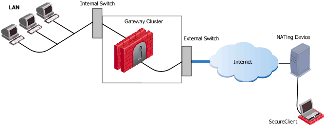
For the connection to survive a failover between cluster members, the "keep alive" feature must be enabled in Global Properties > Remote Access > Enable Back connections from gateway to client
This is also true if the NATing is performed on the Security Gateway cluster side.
When a user connects to the organization from a remote location such as hotel or the offices of a customer, Internet connectivity may be limited to web browsing using the standard ports designated for HTTP, typically port 80 for HTTP and port 443 for HTTPS. Since the remote client needs to perform an IKE negotiation on port 500 or send IPsec packets (which are not the expected TCP packets; IPsec is a different protocol), a VPN tunnel cannot be established in the usual way. This issue is resolved using Visitor Mode, formally known as TCP Tunneling.
Visitor Mode tunnels all client-to-Security Gateway communication through a regular TCP connection on port 443.
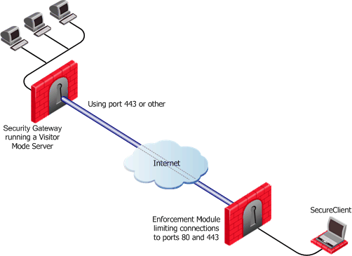
All required VPN connectivity (IKE, IPsec, etc.) between the Client and the Server is tunneled inside this TCP connection. This means that the peer Security Gateway needs to run a Visitor Mode (TCP) server on port 443.
|
Note -
|
To obtain optimal performance of the Visitor Mode server:
The organization decides that it would like to use a customized port for the Visitor Mode Server other than the typically designated port 443. In this scenario, another port that is mutually agreed upon by all the remote locations and the home organization, can be used for Visitor Mode. This solution works well with business partners; the partner simply agrees to open a port for the visitor Mode connections. If the chosen port is not represented by a pre-defined service in SmartDashboard, this service must be created in order for the port to be used. If a port has been mutually agreed upon, and there is a proxy, configure the proxy to allow traffic destined to this port.
|
Note - All partner Security Gateways must agree on the same allocated port, since the visitor Mode server on the peer gateway will be listening on only one port. |
If you change the port for Visitor Mode, see sk103107 for how to create an Endpoint Security VPN site.
Visitor Mode can still be utilized in instances where the remote location runs a proxy server. In this scenario, the remote user enables Visitor Mode connections to pass through the proxy server.
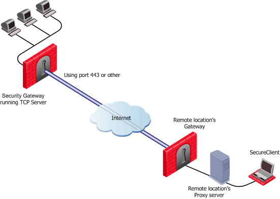
If the designated port is already in use, for example reserved for HTTPS connections by a Server at the organization's Security Gateway, a log is sent "Visitor Mode Server failed to bind to xxx.xxx.xxx.xxx:yy (either port was already taken or the IP address does not exist)" to Security Management Server.
If the peer Security Gateway is already running a regular HTTP server that also listens on the standard HTTPS port 443, then it must be set up with two external interfaces, both of which have public IP addresses — one for the HTTP server, and one for the Visitor Mode server. This second routable address can be achieved in two ways:
On the Security Gateway object running the Visitor Mode server, General Properties > Remote Access page > there is a setting for Allocated IP address. All the available IP addresses can be configured to listen on port 443 for Visitor Mode connections.
SecurePlatform running on Linux and IPSO boxes are installed with a pre-configured HTTPS server; the server runs on the Security Gateway and listens on port 443. Installing an additional network interface or utilizing a virtual IP for the Visitor Mode server is not relevant since these HTTPS servers automatically bind to all available IP addresses.
In this case, it is preferable to reserve 443 for Visitor Mode, since users connecting, for example, from a hotel, may only be allowed to connect via ports 80 and 443. These pre-configured HTTPS servers need to be allocated ports that do not conflict with the Visitor Mode server.
Visitor Mode also works in a MEP environment. For more information, see: Visitor Mode and MEP.
For interface resolution in a Visitor Mode environment, it is recommended to use static IP resolution or dedicate a single interface for Visitor Mode.
This section describes how to configure Remote Access connectivity in SmartDashboard and DBedit.
If the user is not working in connect mode, the user has to manually enable IKE over TCP on the client.
When IKE over TCP is enabled on the Security Gateway, the Security Gateway continues to support IKE over UDP as well. For remote clients, IKE over TCP is supported only for as long as the client works with a profile that enables IKE over TCP.
Small phase II IKE proposals always include AES-256, but not AES-128. Suppose you want to include AES-128 in the small proposals:
|
Note - NAT Traversal (UDP Encapsulation) currently does not support IPv6. |
To configure Nat Traversal on a Security Gateway:
If the user is not working in connect mode, the user has to manually enable UDP Encapsulation on the client. On the client's file menu, Tools > Advanced IKE Settings, select Force UDP Encapsulation.
Selecting UDP encapsulation on the Security Gateway means that the Security Gateway supports both encapsulated VPN traffic and traffic that is not encapsulated.
Visitor Mode requires the configuration of both the Server and the Client. See also: Visitor Mode and MEP.
To enable the TCP tunneling feature on the Security Gateways:
On the Security Gateway object running the Visitor Mode Server, IPsec VPN > Remote Access > Visitor Mode Configuration section, select Support Visitor Mode.
|
Note - When Visitor Mode is activated on the gateway, the RDP interface discovery mechanism does not work. A Visitor Mode handshake is used instead. |
These settings configure a Visitor Mode server to run on the Security Gateway.
Cluster support is limited. The High Availability and Load Sharing solutions must provide "stickiness". That is, the visitor mode connection must always go through the same cluster member.
Failover from cluster member to cluster member in a High Availability scenario is not supported.
Create a customized connection profile for Visitor Mode users. This profile enables the Visitor Mode feature on the Client side.
To create the profile:
On the remote client, configure the user to work in connect mode.
In previous versions, the proxy had to be manually defined.
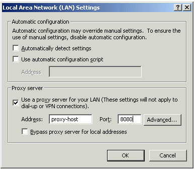
Now SecureClient can read any of the Visitor Mode settings, but only if:
|
Note - Visitor mode attempts to connect to the proxy server without authenticating. If a user name and password is required by the proxy, the error message "proxy requires authentication appears". |
If SecureClient is on a LAN\WLAN and a proxy server is configured on the LAN, SecureClient replaces the proxy settings so that new connections are not sent to the VPN domain via the proxy but go directly to the LAN\WLAN's Security Gateway. This feature works with and without Visitor Mode. SecureClient must be on a WAN\WLAN and not using a dial-up connection.
When SC replaces the proxy file, it generates a similar plain script PAC file containing the entire VPN domain IP ranges and DNS names (to be returned as "DIRECT"). This file is stored locally, since the windows OS must receive this information as a plain script PAC file. This file replaces the automatic configuration script as defined in Internet Explorer:
Sensitive information regarding the site's IP Address and DNS settings are contained in the SecureClient userc.C file. For this reason, the file is obfuscated by an algorithm that hides the real content (but does not encrypt it). When the proxy replacement feature is used, the same information is written to the plain text PAC file. For this reason, administrators should be aware that the Windows Proxy Replacement feature exposes the VPN domain by writing Site IP addresses and DNS settings as Java Script code in this plain text PAC file, which can be viewed by any end user.
Windows proxy replacement is configured either on the Security Gateway or on the Remote Access client.
The Advanced Configuration window opens:
When SecureClient performs an update, the policy regarding windows proxy replacement is downloaded and put into effect.