


|
|
|
In This Section: |
Link Selection is a method used to determine which interface is used for incoming and outgoing VPN traffic as well as the best possible path for the traffic. Using the Link Selection mechanisms, the administrator can choose which IP addresses are used for VPN traffic on each Security Gateway.
Link Selection has many configuration options to enable you to control VPN traffic. These options include:
Configuration settings for remote access clients can be configured together or separately from the Site-to-Site configuration. For more information, see Link Selection for Remote Access Clients.
There are several methods that can determine how remote peers resolve the IP address of the local Security Gateway. These settings are configured in Security Gateway Properties > IPsec VPN > Link Selection. Remote peers can connect to the local Security Gateway with these settings.
Always Use This IP Address:
Configure a certain IP address that is always used. The options are:
Calculate IP Based on Network Topology:
The VPN tunnel is created using an IP address of an external interface on the local gateway. The remote peer selects the first IP address on the list of external interfaces. This method is best when the main IP address of the local gateway is unknown and the external interfaces change frequently.
Use DNS Resolving:
This method is required for Dynamically Assigned IP (DAIP) Security Gateways. A VPN tunnel to a DAIP Security Gateway can only be initiated using DNS resolving since the IP address of the DAIP Security Gateway cannot be known in advance. If using this method for a non-DAIP Security Gateway, the IP address must be defined in the Topology tab. Without DNS resolving, a DAIP Security Gateway can only initiate the first connection between two peers. The second connection can be initiated by the peer Security Gateway as long as the IP address of the DAIP Security Gateway has not changed. The options are:
Use Probing Redundancy Mode:
When more than one IP address is available on a Security Gateway for VPN, Link Selection may employ the RDP probing method to determine which link will be used. The RDP probing method is implemented using a proprietary protocol that uses UDP port 259. This protocol is proprietary to Check Point and works only between Check Point entities. (Note that it does not comply with RDP as specified in RFC 908/1151). IP addresses you do not want to be probed (i.e., internal IP addresses) may be removed from the list of IP’s to be probed. Once a Security Gateway maps the links' availability, a link selection per connection can be made according to the following redundancy modes:
In High Availability mode the VPN tunnel uses the first IP address to respond, or the primary IP address if a primary IP is configured and active. If the chosen IP address stops responding, the connection fails over to another responding IP address. If a primary IP address is configured, the VPN tunnel will stay on the backup IP address until the primary one becomes available again.
Note that if one time probing is configured, the VPN tunnel will stay on the first chosen IP address until the next time policy is installed. See ongoing probing and onetime probing methods below.
In Load Sharing mode the encrypted traffic is distributed among all available links. Every new connection ready for encryption uses the next available link in a round robin manner. When a link becomes unavailable, all of its connections are distributed among the other available links. A link's availability is determined using RDP probing.
The peer Security Gateway that responds to the connection will route the reply traffic through the same route that it was received on, as long as that link is available.
Although the VPN tunnel traffic can be routed through multiple links in Load Sharing mode, only one VPN tunnel is generated. IKE sessions are arbitrarily routed though one of the available links.
Load Sharing is supported on Security Gateways of version R71 and higher. If a Security Gateway of version R71 or higher is configured to use the Load Sharing redundancy mode, Security Gateways of versions before R71 will use the High Availability redundancy mode when routing traffic to the R71 or higher Security Gateways.
Load Sharing is supported on all platforms for incoming traffic. For outgoing traffic, VPN traffic between peers with Load Sharing configuration is not accelerated by IPSO acceleration devices. Load Sharing is not supported on UTM-1 Edge devices.
Probing Settings:
Additional settings related to probing are set in Link Selection > IP Selection by Remote Peer > Use probing > Configure > Probing Settings
Choose one of the following probing methods.
Note - UDP RDP packets are not encrypted. The RDP mechanism only tests connectivity.
The IP address used by a Security Gateway during a successful IKE negotiation with a peer Security Gateway, is used by the peer Security Gateway as the destination IP address for the next IPsec traffic and IKE negotiations that it initiates. This is only the case when the Link Selection configuration does not use probing.
For outbound traffic, there are different methods that can be used to determine which path to use when connecting with a remote peer. These settings are configured in Security Gateway Properties > IPsec VPN > Link Selection.
If you selected the IP Selection by Remote Peer setting of Use probing with Load Sharing, it also affects Route based probing link selection. In this case, Route based probing distributes the outgoing encrypted traffic among all available links. All possible links to the peer Security Gateway are derived from the routing table and the link's availability is tested using RDP probing. Every new connection ready for encryption uses the next available link in a round robin manner.
Route based probing enables the use of On Demand Links (ODL), which are triggered upon failure of all primary links. You can run a script to activate an On Demand Link when all other links with higher priorities become unavailable. For more information, see On Demand Links.
For IKE and RDP sessions, Route based probing uses the same IP address and interface for responding traffic.
Route based probing is supported on the SecurePlatform, Gaia, Linux, and IPSO platforms. VPN traffic between peers with Load Sharing probing mode and Route Based probing configuration will not be accelerated by IPSO acceleration devices.
Notes:
The High Availability mechanism is based on:
resolver_session_interval (30) - Defines for how many seconds the remote peer status (up or down) stays validresolver_ttl (10) - Defines how many seconds the gateway waits before it decides that a remote peer is downSome network protocols (for example, TCP) might timeout in the time between link failure and the next attempt to resolve. Administrators can decrease these default values. Note that high resolution frequency can overload the gateway. This configuration also changes the default resolution timeouts for the MEP mechanism.
For L2 links, there must be routes to the peer's encryption domains through the local L2 interface device.
When responding to a remotely initiated tunnel, there are two options for selecting the interface and next hop that are used. These settings are only relevant for IKE and RDP sessions.
These settings are configured in Link Selection > Outgoing Route Selection > Setup > Link Selection - Responding Traffic window.
Note - When Route Based Probing is enabled, Reply from the same interface is the selected method and cannot be changed.
The local Security Gateway, using RDP probing, considers all possible routes between itself and the remote peer Security Gateway. The Security Gateway then decides on the most effective route between the two Security Gateways:
In this scenario, Security Gateway A has two external interfaces, 192.168.10.10 and 192.168.20.10. Peer Security Gateway B also has two external interfaces: 192.168.30.10 and 192.168.40.10.
For Security Gateway A, the routing table reads:
Destination |
Netmask |
Next hop |
Metric |
|---|---|---|---|
192.168.40.10 |
255.255.255.0 |
192.168.10.20 |
1 |
192.168.40.10 |
255.255.255.0 |
192.168.20.20 |
2 |
192.168.30.10 |
255.255.255.0 |
192.168.10.20 |
3 |
192.168.30.10 |
255.255.255.0 |
192.168.20.20 |
4 |
For Security Gateway B, the routing table reads:
Destination |
Netmask |
Next hop |
Metric |
|---|---|---|---|
192.168.20.10 |
255.255.255.0 |
192.168.40.20 |
1 |
192.168.20.10 |
255.255.255.0 |
192.168.30.20 |
2 |
192.168.10.10 |
255.255.255.0 |
192.168.40.20 |
3 |
192.168.10.10 |
255.255.255.0 |
192.168.30.20 |
4 |
If all routes for outgoing traffic from Security Gateway A are available, the route from 192.168.10.10 to 192.168.40.10 has the lowest metric (highest priority) and is therefore the preferred route.
The source IP address used for outgoing packets can be configured for sessions initiated by the Security Gateway. These settings are configured in Security Gateway Properties > IPsec VPN > Link Selection > Outgoing Route Selection > Source IP address settings.
When initiating a VPN tunnel, set the source IP address using one of the following:
These settings are relevant for RDP and IKE sessions. When responding to an IKE session, use the reply_from_same_IP (default: true) attribute to follow the settings in the Source IP address settings window or to respond from the same IP.
|
Note - When Route Based Probing is enabled, reply_from_same_IP will be seen as true. |
When Outgoing link tracking is activated on the local Security Gateway, the Security Gateway sends a log for every new resolving decision performed with one of its remote VPN peers. If Use Probing is configured on the local Security Gateway for Remote Peer resolving, or if Route Based Probing is activated on the local Security Gateway, log entries are also created for all resolving changes. For example, if a link in use becomes unavailable and a new available link is chosen, a log entry is issued.
Link Selection can be used in many environments. This section describes various scenarios and how Link Selection should be configured in each scenario.
This is the simplest scenario, where the local Security Gateway has a single external interface for VPN:
How do peer Security Gateways select an IP address on the local Security Gateway for VPN traffic?
Since there is only one interface available for VPN, to determine how remote peers determine the IP address of the local Security Gateway, select the following from the IP Selection by Remote Peer section of the Link Selection page:
In this scenario, the local Security Gateway has a point-to-point connection from two different interfaces. Each interface is used by a different remote party:
The local Security Gateway has two IP addresses used for VPN. One interface is used for VPN with a peer Security Gateway A and one interface for peer Security Gateway B.
To determine how peer Security Gateways discover the IP address of the local Security Gateway, enable one-time probing with High Availability redundancy mode. Since only one IP is available for each peer Security Gateway, probing only has to take place one time.
In this scenario, the local Security Gateway has two external interfaces available for VPN. The address of interface eth0 is being translated using a NAT device:
To determine how peer Security Gateways discover the IP address of the local Security Gateway, use ongoing probing with High Availability redundancy mode. In order for the Static NAT IP address to be probed, it must be added to the Probe the following addresses list in the Probing Settings window.
Depending on your configuration, there are many ways to use Load Sharing to distribute VPN traffic among available links between the local and peer Security Gateways.
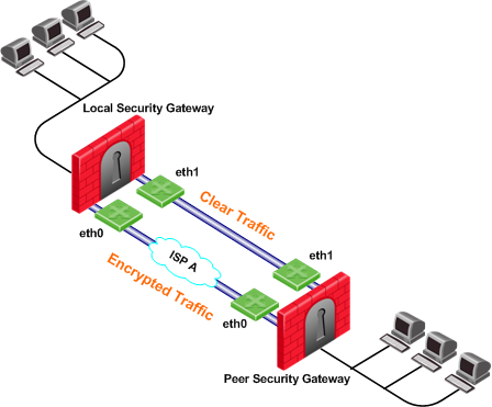
In the following scenario, the local and peer Security Gateways each have two external interfaces available for VPN traffic.
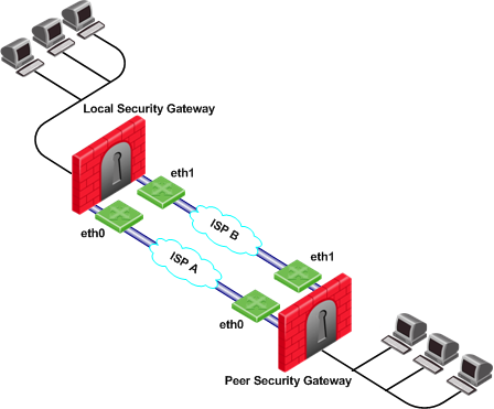
To utilize both external interfaces by distributing VPN traffic among all available links, use the Probing redundancy mode of Load Sharing on both Security Gateways. You can also specify that only certain external interfaces should be probed by putting only those interfaces in the Probe the following addresses list in the Probing Settings window. If one link goes down, traffic will automatically be rerouted through the other link.
To enable this configuration, make sure that your routing table allows packet flow back and forth between both eth0 interfaces and packet flow back and forth between both eth1 interfaces. Then Link Selection can reroute the VPN traffic between these available links.
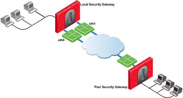
In the following scenario, the local Security Gateway has two external interfaces available for VPN traffic. The peer Security Gateway has one external interface for VPN traffic.
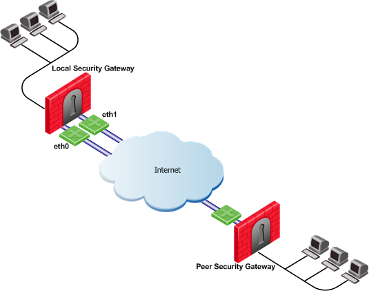
To utilize both external interfaces and distribute VPN traffic between the available links, use the Probing redundancy mode of Load Sharing on the local Security Gateway. Then the peer Security Gateway will distribute its outgoing VPN traffic between interfaces eth0 and eth1 of the local Security Gateway.
If the default, Operating system routing table, setting in the Outgoing Route Selection section is selected, the local Security Gateway will only use one of its local interfaces for outgoing VPN traffic; the route with the lowest metric and best match to reach the single IP address of the peer Security Gateway, according to the routing table.
If you want to distribute the outgoing VPN traffic on both outbound links from the local Security Gateway as well, select Route Based Probing in the Outgoing Route Selection on the Link Selection page of the local Security Gateway.
Service Based Link Selection enables administrators to control outgoing VPN traffic and bandwidth use by assigning a service or a group of services to a specific interface for outgoing VPN routing decisions. The encrypted traffic of an outgoing connection is routed through the configured interface according to the traffic's service. The links to the peer Security Gateway are derived from the routing table and the link's availability is tested using RDP probing.
If all links through the interface assigned to a specific service stop responding to RDP probing, a link failover will occur by default, as in any other probing mode. When a link through the assigned interface is restored, new outgoing connections are assigned to it, while existing connections are maintained over the backup link until they are completed.
It is possible to configure the traffic of a specific service not to fail over. In this case, traffic of the configured service will only be routed through interfaces assigned to this service, even if these interfaces stop responding to RDP.
If the same service is assigned to more than one interface, this service's traffic is distributed between the configured interfaces. Every new outgoing encrypted connection uses the next available link in a round robin manner.
All traffic from services that are not assigned to a specific interface is distributed among the remaining interfaces. If all links through these interfaces are down, the traffic is distributed among the interfaces that are configured for specific services.
Service Based Link Selection configuration requires enabling the following features:
Service Based Link Selection is supported on Security Gateways of version R71 and higher. It is supported on the SecurePlatform, Gaia, Linux, and IPSO platforms. VPN traffic between peers with Service Based Link Selection configuration is not accelerated by IPSO acceleration devices. Service Based Link Selection is not supported on UTM-1 Edge devices.
To configure Service Based Link Selection:
Edit the Service Based Link Selection configuration in the $FWDIR/conf/vpn_service_based_routing.conf configuration file on the management server.
Fill in each line in the configuration file to specify the target Security Gateway, the interface for outgoing routing, and the service (or services group) to route through this interface. Use the names defined in the SmartDashboard GUI. Fill in all of the details for each Security Gateway on which you want to configure Service Based Link Selection.
The fields are:
The following scenarios provide examples of how Service Based Link Selection can be utilized.
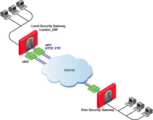
In the scenario below, the local and peer Security Gateways each have two external interfaces for VPN traffic.
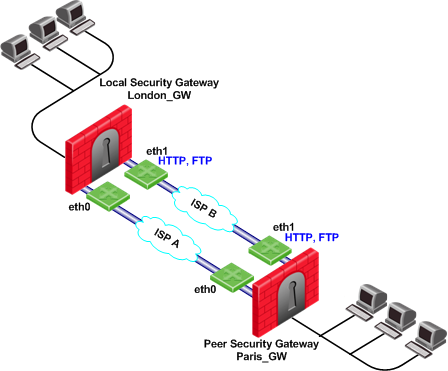
In this example, interface eth1 of both Security Gateways is dedicated to HTTP and FTP traffic. All other traffic is routed to interface eth0.
If the available link through eth1 stops responding to RDP probing, HTTP and FTP traffic will fail over to eth0. It is possible to specify that HTTP and FTP traffic should only be routed through eth1 even if the link through eth1 stops responding. Specify this by including the dont_failover flag when editing the Service Based Link Selection configuration file.
All other traffic that is not HTTP or FTP will be routed through eth0. If the link through eth0 stops responding to RDP probing, all traffic will be routed through eth1.
The Service Based Link Selection configuration file for this environment should appear as follows:
Gateway |
Interface |
Service |
[dont_failover] |
London_GW |
eth1 |
http |
|
London_GW |
eth1 |
ftp |
|
Paris_GW |
eth1 |
http |
|
Paris_GW |
eth1 |
ftp |
|
Alternatively, in SmartDashboard, you can create a Services Group that includes HTTP and FTP services. In the example below, this group is called http_ftp_grp. Using this group, the Service Based Link Selection configuration file for this environment should appear as follows:
Gateway |
Interface |
Service |
[dont_failover] |
London_GW |
eth1 |
http_ftp_grp |
|
Paris_GW |
eth1 |
http_ftp_grp |
|
In the following scenario, the local and peer Security Gateways each have three external interfaces available for VPN.
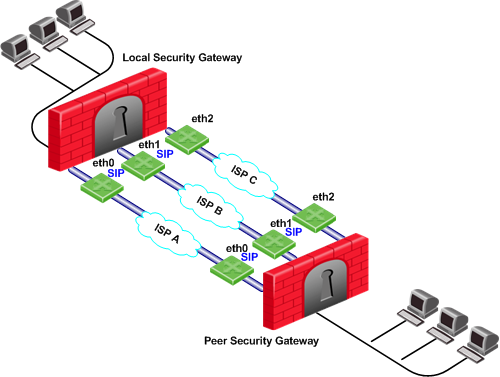
To utilize all three external interfaces and distribute the VPN traffic among the available links, Link Selection Load Sharing and Route based probing should be enabled. To control your bandwidth use, dedicate one or more links to a specific service or services using Service Based Link Selection. In this scenario, interfaces eth0 and eth1 of both Security Gateways are dedicated to SIP traffic. SIP traffic is distributed between eth0 and eth1. All other traffic is routed through eth2.
If either the link through eth0 or the link through eth1 stops responding to RDP probing, SIP traffic will fail over to the other SIP interface. If the link through eth2 stops responding to RDP probing, all traffic will be routed though eth0 or eth1.
In the following scenario, the local Security Gateway has two external interfaces available for VPN traffic. The peer Security Gateway has a single external interface for VPN traffic.
To utilize all external interfaces and distribute the VPN traffic among the available links, Link Selection Load Sharing and Route based probing should be enabled on the local Security Gateway, London_GW. To control your bandwidth use, dedicate interface eth1 of the local Security Gateway to HTTP and FTP traffic using Service Based Link Selection. The local Security Gateway will route outgoing HTTP and FTP connections through interface eth1. All other traffic, not HTTP or FTP, will be routed through eth0.
In this scenario, HTTP and FTP traffic should not fail over. HTTP and FTP traffic should only be routed through interface eth1, even if the link through interface eth1 stops responding to RDP probing. This is configured by specifying the dont_failover flag.
The Service Based Link Selection configuration file for this environment should appear as follows:
Gateway |
Interface |
Service |
[dont_failover] |
London_GW |
eth1 |
http |
dont_failover |
London_GW |
eth1 |
ftp |
dont_failover |
Since the Service Based Link Selection configuration is only relevant for outgoing traffic of the local Security Gateway, the peer Security Gateway can send HTTP and FTP traffic to either interface of the local Security Gateway. The outgoing VPN traffic of the peer Security Gateway is distributed between interfaces eth0 and eth1 of the local Security Gateway.
Trusted Links allows you to set an interface as "trusted" for VPN traffic so that traffic sent on that link will not be encrypted. You may want to set up a trusted link if you are confident that the link is already encrypted and secure and you do not need a second encryption.
If you configure an interface as trusted, traffic routed through that interface will be sent unencrypted, while traffic sent through other interfaces will still be encrypted.
Trusted interfaces should be configured symmetrically on the local and peer Security Gateways. If only one side of the link is configured as trusted for VPN traffic, clear traffic received by a non-trusted interface will be dropped by the peer Security Gateway.
If you have configured a specific link as trusted for VPN traffic and you are using probing, the probing method considers all links, including the trusted link, when choosing a link for a connection.
The probing method chooses the link according to these criteria:
If the trusted link is chosen for a connection, the traffic is not encrypted. If another, non-trusted, link is chosen, the traffic is encrypted.
In an MEP configuration, trusted links are only supported for connections initiated by a peer Security Gateway to a MEP Security Gateway. Unencrypted VPN connections routed through a trusted interface and initiated by a MEP Security Gateway may be dropped by the peer Security Gateway.
Trusted links are not supported in Traditional mode. In Traditional mode, trusted link settings are ignored and VPN traffic is always encrypted.
Trusted links are supported on Security Gateways of version R71 and higher.
|
Note - Trusted links are not supported by IPSO acceleration devices. IPSO acceleration devices ignore trusted links settings and will encrypt traffic routed through these links. |
Use the GuiDBedit Tool (see sk13009) to configure Trusted Links.
To configure a trusted link:
officialname attribute vpn_trusted attribute to true (default value: false).In the following scenario, both the local and peer Security Gateways have two external interfaces available for VPN traffic. Interface eth1 on both Security Gateways has been configured as a trusted interface. Therefore traffic sent from eth1 of the local Security Gateway will be sent unencrypted and will be accepted by interface eth1 of the peer Security Gateway, and vice versa.
If the probing redundancy mode is High Availability and the trusted link is configured as the Primary IP address, the trusted link will be used for VPN traffic. If the trusted link stops responding to RDP probing, the link through Interface eth0 will be used for VPN traffic and traffic will be encrypted.
If the probing redundancy mode is Load Sharing, the VPN traffic will be distributed between the available links. Connections routed through interface eth0 will be encrypted while connections routed through the trusted link will not be encrypted.
In the following scenario, the local and peer Security Gateways have two external interfaces available for VPN traffic. Interface eth1 on both Security Gateways is configured as a trusted interface for VPN traffic since encryption is not needed on that link. In addition, interface eth1 of both Security Gateways is dedicated to SIP traffic using Service Based Link Selection.
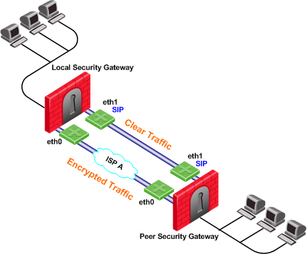
SIP traffic is routed through the trusted link between the two eth1 interfaces and will not be encrypted. If the trusted link stops responding to RDP probing, SIP traffic will be routed through the eth0 interfaces and will be encrypted.
All other traffic that is not SIP is encrypted and routed through the interface eth0 link. However, if interface eth0 stops responding to RDP probing, all the traffic will be routed through the trusted link and will not be encrypted.
Route based probing enables use of an On Demand Link (ODL), which is triggered upon failure of all primary links. When a failure is detected, a custom script is used to activate the ODL and change the appropriate routing information. The ODL's metric must be set to be larger than a configured minimum in order for it to be considered an ODL.
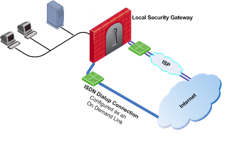
The Security Gateway has two external links for Internet connectivity: one to an ISP, the other to an ISDN dialup. The ISDN dialup connection is configured as an On Demand Link.
On the Security Gateway, the Route Based Probing mechanism probes all of the non-On Demand Links and selects the active link with the lowest metric. In this case, it probed the ISP link. A script is run to activate the On Demand Link when all other links with higher priorities become unavailable. When the link becomes available again, a shutdown script is run automatically and the connection continues through the link with the ISP.
|
Note - On Demand Links are probed only once using a single RDP session. Fail over between On Demand Links is not supported. |
You can enable On Demand Links only if you enabled Route Based Probing. Configure On Demand Links commands in GuiDBedit Tool (see sk13009).
Property |
Description |
|---|---|
use_on_demand_links |
Enables on-demand links. The default is FALSE. Change to TRUE. |
on_demand_metric_min |
Defines the minimum metric level for an on-demand link. This value must be equal to or higher than the configured minimum metric. |
on_demand_initial_script |
The name of the on-demand script, which runs when all not-on-demand routes stop responding. Put the script in the |
on_demand_shutdown_script |
This script is run when the failed links become available. Put the script in the |
If you do not want to use GuiDBedit Tool, you can configure the use_on_demand_links and on_demand_metric_min commands in SmartDashboard:
ISP Redundancy enables reliable Internet connectivity by allowing a single or clustered Security Gateway to connect to the Internet via redundant ISP connections. As part of standard VPN installation, it offers two modes of operation that are configured in Check Point > Security Gateway > Other > ISP Redundancy:
The settings configured in the ISP Redundancy window are by default, applied to the Link Selection page and will overwrite any pre-existing configuration. The following settings carry over:
If you do not want the ISP Redundancy settings to affect the Link Selection settings, on the ISP Redundancy page, clear the check box that says Apply settings to VPN traffic and configure the required VPN settings on the Link Selection page. This may apply when you want to route VPN traffic differently than the firewall traffic. For example, if you want to use Load Sharing for firewall traffic and High Availability for VPN traffic, or if you want to use different primary ISPs for firewall and VPN traffic.
In the following scenario, the local Security Gateway maintains links to ISPs A and B, both of which provide connectivity to the Internet using ISP Redundancy.
In the Topology > ISP Redundancy window, configure the ISP Redundancy settings, such as ISP Links and Redundancy mode. The ISP Redundancy settings are applied by default to VPN traffic. The derived Link Selection settings are visible in the IPsec VPN > Link Selection window.
In the following scenario, the Apply settings to VPN traffic on the ISP Redundancy page was cleared and there are different setting configured for Link Selection and ISP Redundancy.
In this scenario:
In this scenario, the administrator of Security Gateway A needs to:
RDP probing, the probing method used for certain Link Selection features, is proprietary to Check Point and only works between Check Point entities. It is not supported with non-Check Point devices.
Since RDP probing is not active on non-Check Point gateways, the following results apply if a Check Point Security Gateway sends VPN traffic to a non-Check Point gateway:

