Creating a Strong Firewall Security Policy
Using the Firewall Rule Base
The firewall is the core of a well-defined network security policy. The goal of the Check Point Firewall Rule Base is to create rules that only allow the specified connections.
Managing the Firewall Rule Base
Use SmartDashboard to easily create and configure Firewall rules for a strong security policy.
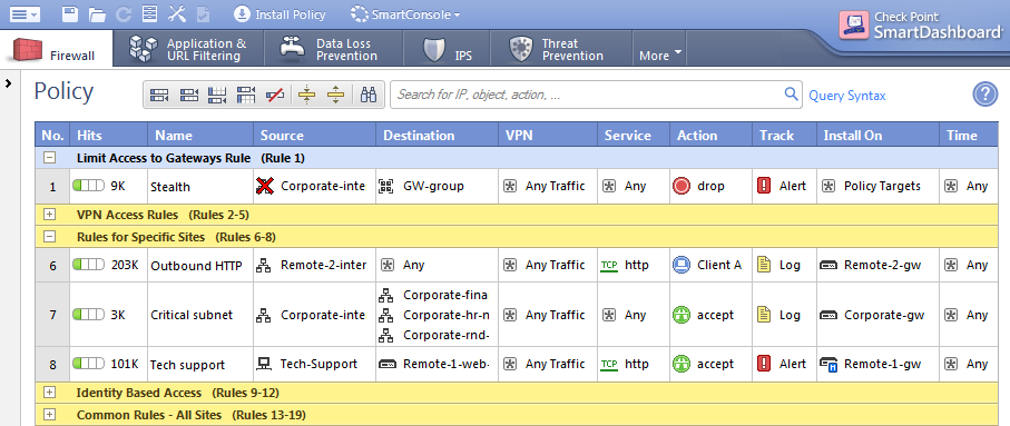
These are the fields that manage the rules for the Firewall security policy.
Field
|
Description
|
No.
|
Rule number in the Firewall Rule Base. Implied rules do not have a number.
|
Hits
|
Number of connections that match this rule.
|
Name
|
Name that the system administrator gives this rule.
|
Source
|
Network object that starts the connection.
|
Destination
|
Network object that completes the connection.
|
VPN
|
Definitions of the allowed or blocked traffic between VPN sites.
|
Service
|
Type of network service that is allowed or blocked.
|
Action
|
Firewall action that is done when traffic matches the rule.
|
Track
|
Tracking and logging action that is done when traffic matches the rule.
|
Install On
|
Network objects that will get the rule(s) of the security policy. The option installs the rule(s) on all Security Gateways.
|
Time
|
Time period that the Firewall enforces this rule.
|
Comment
|
An optional field that lets you summarize the rule.
|

|
Note - The X11 (X Window System Version 11) graphics display system is the standard graphics system for the Unix environment. To enable X11, create a specific rule that allows the X11 service. If you select as the or , the X11 service is not included.
|
Explicit and Implied Rules
These are the types of rules in the Rule Base:
- Explicit rules - Rules that you create to configure which connections the Firewall allows
- Implied rules - Rules that are based on settings in the menu
Implied rules allow connections for different services that the Security Gateway uses. For example, the option allows packets that control these services:
- Installing the security policy on a Security Gateway
- Sending logs from a Security Gateway to the Security Management Server
- Connecting to third party applications, such as RADIUS and TACACS authentication servers
To show the implied rules in the Policy window:
- Make sure there is at least one rule in the Rule Base.
- Click View > Implied Rules.
The window in the tab shows the Rule Base with the explicit and implied rules.
To configure the implied rules:
- Click > .
- From the navigation tree, click .
- Select a rule to enable it, or clear a rule to disable it.
- For the enabled rules, select the position of the rules in the Rule Base.
- Click and install the policy.
Order of Rule Enforcement
The Firewall inspects connections and enforces the Rule Base in a sequential manner. The Firewall inspects each connection that comes to the network and compares the data (source, destination, service, etc.) to the first rule. If the connection matches the rule, the Firewall applies the action of that rule. If the connection does not match the rule, the Firewall continues with the next rule in the Rule Base.
|
|
|
|
|
|
|
|
|
Request to open connection
|

|
Firewall compares connection data to rule
|
|
Does the data the match the rule?
|
Yes
|
Rule action is applied to the connection
|
|
|

|
|
No 
|
|
|
|
|

|

|
Firewall continues with next rule
|
|
|
|
Note - We recommend that you create a Cleanup rule as the final rule in the Rule Base. This rule matches all connections and drops them.
|
Make sure that you understand the importance of the order of rule enforcement to maximize the security of the Firewall. The Firewall always enforces the first rule that matches a connection. It does not enforce later rules that can be more applicable.
This is the order that rules are enforced:
- First Implied Rule: You cannot edit or delete this rule and no explicit rules can be placed before it.
- Explicit Rules: These are rules that you create.
- Before Last Implied Rules: These implied rules are applied before the last explicit rule.
- Last Explicit Rule: We recommend that you use the Cleanup rule as the last explicit rule.
- Last Implied Rules: Implied rules that are configured as in Global Properties.
- Implied Drop Rule: Drops all packets without logging.
|
Note - If you use the Cleanup rule as the last explicit rule, the and the are not enforced.
|
Creating a Secure Firewall Rule Base
Basic Rules
These are basic access control rules we recommend for all Rule Bases:
Sample Firewall Rule Base
This table shows a sample Firewall Rule Base for a typical security policy. (The and columns are not shown.)
No
|
Name
|
Source
|
Destination
|
Service
|
Action
|
Track
|
Install On
|
1
|
Stealth
|
NOT internal
|
GW-group
|
Any
|
Drop
|
Alert
|
Policy Targets
|
2
|
Critical subnet
|
Internal
|
Finance
HR
R&D
|
Any
|
Accept
|
Log
|
CorpGW
|
3
|
Tech support
|
TechSupport
|
Remote1-web
|
HTTP
|
Accept
|
Alert
|
Remote1GW
|
4
|
DNS server
|
Any
|
DNS
|
Domain UDP
|
Accept
|
None
|
Policy Targets
|
5
|
Mail and Web servers
|
Any
|
DMZ
|
HTTP
HTTPS
SMTP
|
Accept
|
Log
|
Policy Targets
|
6
|
SMTP
|
Mail
|
NOT Internal
net group
|
SMTP
|
Accept
|
Log
|
Policy Targets
|
7
|
DMZ & Internet
|
IntGroup
|
Any
|
Any
|
Accept
|
Log
|
Policy Targets
|
8
|
Clean up rule
|
Any
|
Any
|
Any
|
Drop
|
Log
|
Policy Targets
|
- - All traffic that is NOT from the internal company network to one of the Security Gateways is dropped. When a connection matches the Stealth rule, an alert window opens in SmartView Monitor.
- - Traffic from the internal network to the specified resources is logged. This rule defines three subnets as critical resources: Finance, HR, and RnD.
- - Allows the Technical Support server to access the Remote-1 web server which is behind the Remote-1 Security Gateway. Only HTTP traffic is allowed. When a packet matches the Tech support rule, the Alert action is done.
- - Allows UDP traffic to the external DNS server. This traffic is not logged.
- - Allows incoming traffic to the mail and web servers that are located in the DMZ. HTTP, HTTPS, and SMTP traffic is allowed.
- - Allows outgoing SMTP connections to the mail server. Does not allow SMTP connections to the internal network, to protect against a compromised mail server.
- - Allows traffic from the internal network to the DMZ and Internet.
- - Drops all traffic. All traffic that is allowed matched one of the earlier rules.
Defining Security Zones
Networks use different security zones to protect very important resources and to defend against malware. Create rules that allow only the applicable traffic in and out of a security zone. Make sure that there are different rules in the Firewall Rule Base that define traffic to and from the security zones. These are the key elements that define security zones:
- External network - Insecure data, such as the Internet
- Internal network - Company data that is only used by trusted and authenticated users
- Perimeter - The border between the internal and external networks.
- DMZ - Company servers that can be accessed from insecure sources, such as the Internet
Perimeter
The Firewall on the perimeter of the network is responsible for all the incoming and outgoing traffic. These are some of the connections that are usually allowed by a Firewall on the perimeter:
- Outgoing connections to the Internet
- Connections to the DNS server
- Specified external connections
- Connections to servers in the DMZ
- Connections from the internal network to the internal network
- VPN connections
DMZ
Servers that are accessed by the Internet are usually located in a DMZ (demilitarized zone). The DMZ makes sure that these servers cannot connect to the internal network. Make sure that the Rule Base contains rules for DMZ traffic. For example, these are rules for a web server in the DMZ:
- A rule that allows HTTP and HTTPs traffic to the DMZ network object
- A rule that allows traffic from the internal network group object to any destination (the destination includes the DMZ)
Preventing IP Spoofing
Attackers use IP spoofing to make the IP address of a packet appear to be from a trusted source. This can bypass the Firewall to introduce malicious content and actions (malware and bot downloads, DoS attacks, unauthorized access, and so on) to your network.
Anti-Spoofing detects if a packet with an IP address that is, according to the topology, behind one interface, actually arrives from a different interface. For example, if a packet from an external network has an internal IP address, Anti-Spoofing blocks the packet.
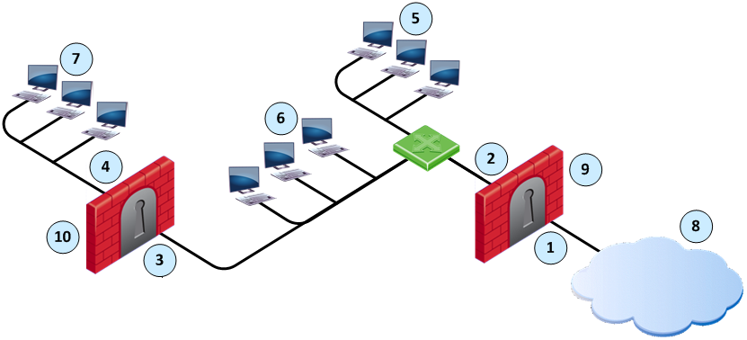
Item
|
Description
|
|
Item
|
Description
|
1
|
Interface IF1
|
|
6
|
Florida_LAN
|
2
|
Interface IF2
|
|
7
|
Alaska_RND_LAN
|
3
|
Interface IF3
|
|
8
|
Internet
|
4
|
Interface IF4
|
|
9
|
Alaska_GW
|
5
|
Alaska_LAN
|
|
10
|
Alaska_RND_GW
|
For the Alaska_GW, the Firewall makes sure that:
- All incoming packets to IF1 come from the Internet.
- All incoming packets to IF2 come from Alaska_LAN or, Alaska_RND_LAN or Florida_LAN.
For the Alaska_RND_GW, the Firewall makes sure that:
- All incoming packets to IF3 come from Alaska_LAN, Florida_LAN or the Internet.
- All incoming packets to IF4 come from Alaska_RND_LAN.
When you configure Anti-Spoofing for a Security Gateway, specify if the interfaces go to the Internet (External) or an internal network (Internal).
Configuring Anti-Spoofing
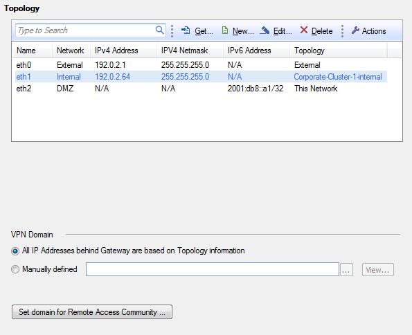
Use the Topology page to configure Anti-Spoofing for the external and internal interfaces on the Security Gateway. Configure Anti-Spoofing protection on all the interfaces of the Security Gateway, including internal interfaces.
SmartDashboard attempts to automatically retrieve the topology from the Security Gateway. If it cannot retrieve the topology information, make sure that:
- The details in the Security Gateway window are correct.
- The Security Gateway, the Security Management Server, and the SmartDashboard can communicate with each other.
When you configure an internal interface, select the option for the IP addresses that are connected to the interface. These are the network options:
- - All IP addresses are considered as part of the internal network that connects to this internal interface.
- - There is only one network that connects to this internal interface.
- - There is more than one network that connects to this internal interface. Select the group network object that contains all the appropriate networks.
To configure Anti-Spoofing for an interface:
- In SmartDashboard, from the tree, double-click the Security Gateway.
The window opens.
- From the navigation tree, click .
- Click > .
- Click .
- Select the interface that connects to the Internet and click .
The window opens.
- Click the tab.
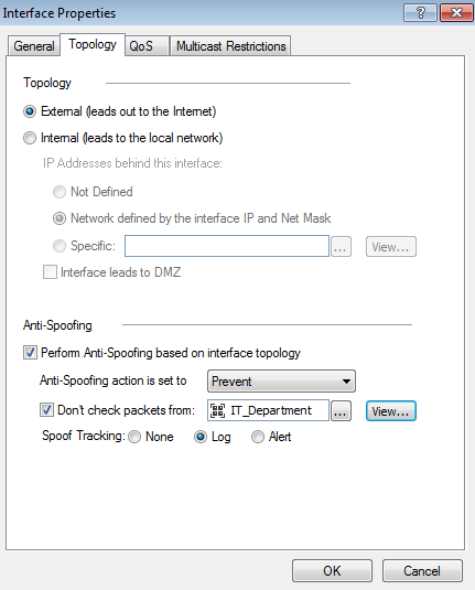
- Select or .
- For interfaces, do these steps:
- Select the option for the network .
- If the internal interface connects to a DMZ, select .
- Select .
- Select an .
- Optional for External Interfaces: Configure the IP addresses that are not included in Anti-Spoofing.
- Select .
- Click the field, and select the Group or Network object that you are not including in Anti-Spoofing.
You can click to create a new Group or Network object.
- From , select the tracking action that is done when Anti-Spoofing is detected.
- Click and configure Anti-Spoofing for all the interfaces on the Security Gateway.
- Click and install the policy.
Excluding Specific Internal Addresses
In some configurations, the Firewall must allow connections with an internal IP address from an external source. For example, an external application can assign internal IP addresses to external clients. You can configure the Anti-Spoofing protection on the external interfaces to ignore connections from these IP addresses. The Firewall allows these connections and does not inspect them.
Analyzing the Rule Base (Hit Count)
Use the Hit Count feature to track the number of connections that each rule matches. You can show Hit Count for the rules in these options:
- The percentage of the rule hits from total hits
- The indicator level (very high, high, medium, low, or zero)
These options are configured in the Firewall Rule Base and also changes how Hit Count is shown in other supported Software Blades.
When you enable Hit Count, the Security Management Server collects the data from supported Security Gateways (from version R75.40 and up). Hit Count works independently from logging and tracks the hits even if the option is .
You can use the Hit Count data to:
- Analyze a Rule Base - You can delete rules that have no matching connections
|
Note - If you see a rule with a zero hit count it only means that in the Security Gateways enabled with Hit Count there were no matching connections. There can be matching connections on other Security Gateways.
|
- Better Firewall performance - You can move a rule that has a high hit count to a higher position in the Rule Base
- Better understand the behavior of the security Policy
Enabling or Disabling Hit Count
By default, Hit Count is globally enabled for all supported Security Gateways (from R75.40). The timeframe setting that defines the data collection time range is configured globally. If necessary, you can disable Hit Count for one or more Security Gateways.
After you enable or disable Hit Count you must install the Policy for the Security Gateway to start or stop collecting data.
To enable or disable Hit Count globally:
- From the menu, select .
- Select from the tree.
- Select the options:
- Select to enable or clear to disable all Security Gateways to monitor the number of connections each rule matches.
- Select one of the time range options. The default is 6 months. Data is kept in the Security Management Server database for this period and is shown in the Hits column.
- Click and then install the Policy.
To enable or disable Hit Count on each Security Gateway:
- From the for the Security Gateway, select from the navigation tree.
- Select to enable the feature or clear it to disable Hit Count.
- Click and then install the Policy.
Configuring the Hit Count Display
These are the options you can configure for how matched connection data is shown in the column:
- - Shows the number of matched hits for the rule from supported Security Gateways. Connection hits are not accumulated in the total hit count for:
- Security Gateways that are not supported (versions before R75.40)
- Security Gateways that have disabled the hit count feature
The values are shown with these letter abbreviations:
- K = 1,000
- M = 1,000,000
- G = 1,000,000,000
- T = 1,000,000,000,000
For example, 259K represents 259 thousand connections and 2M represents 2 million connections.
- Shows the percentage of the number of matched hits for the rule from the total number of matched connections. The percentage is rounded to a tenth of a percent.
- The hit count level is a label for the range of hits according to the table.
The hit count range = Maximum hit value - Minimum hit value (does not include zero hits)
Hit Count Level
|
Icon
|
Range
|
Zero
|

|
0 hits
|
Low
|

|
Less than 10 percent of the hit count range
|
Medium
|

|
Between 10 - 70 percent of the hit count range
|
High
|

|
Between 70 - 90 percent of the hit count range
|
Very High
|

|
Above 90 percent of the hit count range
|
To configure the Hit Count display:
- Right-click the column header or the rule number in the row.
- From the menu, select .
- Select one or more options:
|
|

