


|
|
|
In This Section: |
ClusterXL is a software-based Load Sharing and High Availability solution that distributes network traffic between clusters of redundant Security Gateways.
ClusterXL has these High Availability features:
All members in the cluster are aware of the connections passing through each of the other members. The cluster members synchronize their connection and status information across a secure synchronization network.
The glue that binds the members in a ClusterXL cluster is the Cluster Control Protocol (CCP), which is used to pass synchronization and other information between the cluster members.
In a High Availability cluster, only one member is active (Active/Standby operation). In the event that the active cluster member becomes unavailable, all connections are re-directed to a designated standby without interruption. In a synchronized cluster, the standby cluster members are updated with the state of the connections of the active cluster member.
In a High Availability cluster, each member is assigned a priority. The highest priority member serves as the Security Gateway in normal circumstances. If this member fails, control is passed to the next highest priority member. If that member fails, control is passed to the next member, and so on.
Upon Security Gateway recovery, you can maintain the current active Security Gateway (Active Up), or to change to the highest priority Security Gateway (Primary Up).
ClusterXL High Availability supports IPv4 and IPv6.
ClusterXL Load Sharing distributes traffic within a cluster so that the total throughput of multiple members is increased. In Load Sharing configurations, all functioning members in the cluster are active, and handle network traffic (Active/Active operation).
If any member in a cluster becomes unreachable, transparent failover occurs to the remaining operational members in the cluster, thus providing High Availability. All connections are shared between the remaining Security Gateways without interruption.
IPv6 is not supported for Load Sharing clusters.
ClusterXL uses unique physical IP and MAC addresses for each cluster member, and a virtual IP addresses for the cluster itself. Cluster interface addresses do not belong to any real member interface.
The following diagram illustrates a two-member ClusterXL cluster, showing the cluster virtual IP addresses and member physical IP addresses. This sample deployment is used in many of the examples presented in this chapter.
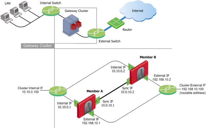
Each cluster member has three interfaces: one external interface, one internal interface, and one for synchronization. Cluster member interfaces facing in each direction are connected via a switch, router, or VLAN switch.
All cluster member interfaces facing the same direction must be in the same network. For example, there must not be a router between cluster members.
The Security Management Server can be located anywhere, and should be routable to either the internal or external cluster addresses.
These sections present ClusterXL configuration concepts shown in the example.
|
Note 2. In these examples, RFC 1918 private addresses in the range |
The guidelines for configuring each cluster member are as follows:
All members within the cluster must have at least three interfaces:
All interfaces pointing in a certain direction must be on the same network.
For example, in the previous illustration, there are two cluster members, Member_A and Member_B. Each has an interface with an IP address facing the Internet through a hub or a switch. This is the external interface with IP address 192.168.10.1 on Member_A and 192.168.10.2 on Member_B, and is the interface that the cluster external interface sees.
|
Note - This release presents an option to use only two interfaces per member, one external and one internal and to run synchronization over the internal interface. This configuration is not recommended and should be used for backup only. |
In the previous illustration, the IP address of the cluster is 192.168.10.100.
The cluster has one external virtual IP address and one internal virtual IP address. The external IP address is 192.168.10.100, and the internal IP address is 10.10.0.100.
The previous illustration shows a synchronization interface with a unique IP address on each cluster member - IP 10.0.10.1 on Member_A and IP 10.0.10.2 on Member_B.
Only one public IP address is required in a ClusterXL cluster, for the virtual cluster interface that faces the Internet. Physical IP addresses of all cluster members can be private.
Configuring different subnets for the cluster IP addresses and the members IP addresses is useful in order to:

