Configuring ClusterXL
This procedure describes how to configure the Load Sharing Multicast, Load Sharing Unicast, and High Availability New Modes from scratch. Their configuration is identical, apart from the mode selection in SmartDashboard Gateway Cluster object or Gateway Cluster creation wizard.
If you are still using the High Availability Legacy Mode, refer to the appendix.
Preparing Cluster Members
To prepare cluster members:
- Obtain and install a ClusterXL central license on your Security Management server.
- Install and configure Check Point Security Gateway on all cluster members. Each member must use the identical version and build. For installation and initial configuration procedures, refer to the R76 Installation and Upgrade Guide.
- During installation process, enable ClusterXL and State Synchronization by selecting Enable cluster membership for this gateway for Secure Platform and Solaris members, or This Gateway is part of a cluster for Windows-based members.
If you did not perform this action during installation, you can always do so by using the cpconfig utility at a later time. Run the cpconfig from the command line, and select the appropriate options to enable cluster capabilities for that member. You may be asked to reboot the member.
- Define an IP address for each interface on all members.
- For VPN cluster members, synchronize member clocks accurately to within one second of each other. If these members are constantly up and running it is usually enough to set the time once. More reliable synchronization can be achieved using NTP or some other time synchronization services supplied by the operating system. Cluster member clock synchronization is not relevant for non VPN cluster functionality.
- Connect the cluster members to each other and to the networks via switches. For the synchronization interfaces, you can use a cross cable or a dedicated switch. Make sure that each network (internal, external, Synchronization, DMZ, and so on) is configured on a separate VLAN, switch or hub.
Configuring Routing for Client Machines
To configure routing for the client machines:
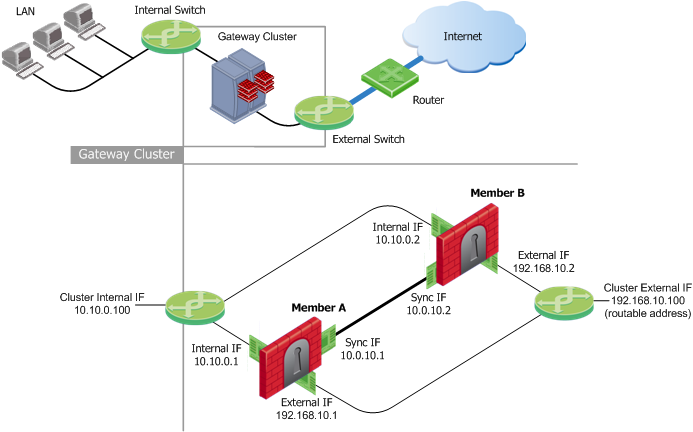
- Configure routing so that communication with internal networks uses the external cluster IP address. For example, configure a static route such that internal network 10.10.0.0 is reached via 192.168.10.100.
- Configure routing so that communication with external networks uses the internal cluster IP address. For example, define the internal network IP address 10.10.0.100 as the default gateway for each computer on the internal side of the router.
Choosing the CCP Transport Mode on the Cluster Members
The ClusterXL Control Protocol (CCP) uses multicast by default, because it is more efficient than broadcast. If the connecting switch cannot forward multicast traffic, it is possible, though less efficient, for the switch to use broadcast to forward traffic.
To toggle the CCP mode between broadcast and multicast:
Configuring Cluster Objects & Members
Introduction
Use the Cluster object Topology page to configure the topology for the cluster object and its members. The cluster IP addresses are virtual, as they do not belong to any physical interface. Assign one or more synchronization network interfaces for each cluster member.
The following network diagram illustrates a typical ClusterXL deployment and is used in many of the examples presented with the procedures in this chapter.
To define a new Gateway Cluster object:
- In the Network Objects tree, right-click Check Point and then select Security Cluster.
- If the Security Gateway Cluster Creation window appears, select one of the following methods to create your new cluster object:
- Simple Mode (Wizard), which guides you step by step through the configuration process. Refer to the online help for further assistance.
- Classic Mode, as described in the following section.
Using the Wizard
Classic Mode Configuration
Configuring General Properties
To configure the general properties of a cluster:
- Enter a unique name for this cluster object in the designated field.
- Enter the main cluster IP address.
- Select ClusterXL as a product installed on the cluster.
- Enable ClusterXL and other Network Security Software Blades as appropriate.
Defining Cluster Members
To configure a cluster member:
- On the Cluster Members page, click Add > New Cluster Member.
- In the Cluster Members Properties window General tab, enter a member Name and a physical IP Address, which must be routable from the Security Management server. This can be an internal or an external address, or a dedicated management interface.
- Click Communication, and initialize Secure Internal Communication (SIC) trust.
- Configure NAT and VPN settings on the appropriate tabs as required. For more details, refer to the R76 Security Management Administration Guide.
Adding an Existing Gateway as a Member
To add an existing gateway as a cluster member, select Add > Add Gateway to Cluster on the Cluster Members page and select a gateway from the list in the Add Gateway to Cluster window.
Removing a Member
To remove a gateway from the cluster, click Remove in the Cluster Members page and select Detach Member from Cluster or right-click on the cluster member in the Network Objects tree and select Detach from Cluster.
Configuring ClusterXL Properties
To Configure ClusterXL properties:
- For High Availability deployments, enable the High Availability option and
- Select one of the following modes:
- Select the action to perform upon primary member recovery:
- Maintain the current active cluster member
- Switch back to a higher priority cluster member
- For Load Sharing deployments, enable the Load Sharing option and select one of the following modes according to your router's capabilities:
- Multicast (Default)
- Unicast
- Enable the Use State Synchronization option as indicated:
- Load Sharing configurations require State Synchronization. This option is enabled by default and you cannot disable it.
- For High Availability New deployments, State Synchronization is optional, but enabled by default. If you choose to disable State Synchronization, cluster members do not synchronize, and existing connections on the failed gateway will be terminated once failover occurs.
- Select tracking options from the list.
Configuring the Cluster Topology
- In the Topology page, click Edit Topology to define the virtual cluster IP addresses and at least one synchronization network.
- In the Edit Topology window:
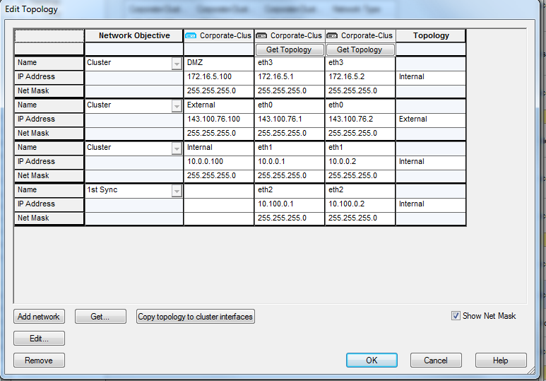
- Define the topology for each member interface. To automatically read all predefined settings on member interfaces, click Copy topology to cluster interfaces.
In the Network Objective column, select an objective for each network from the list. The various options are explained in the online help. To define a new network, click Add Network.
- Define the topology for each virtual cluster interface. In a virtual cluster interface cell, right click and select Edit Interface. The Interface Properties window opens.
- In the General tab, Name the virtual interface, and define an IP Address.
- In the Topology tab, define whether the interface is internal or external, and set up anti-spoofing.
If you select:
- and
- contains a group, then:
The group must contain the Sync IP addresses of all the members.
- In the Member Networks tab, define the member network and net mask if necessary. This advanced option is explained in Configuring Cluster Addresses on Different Subnets.
Completing the Definition
- Define the other pages in the cluster object as required (NAT, VPN, Remote Access, and so on).
- Install a Security Policy on the cluster.
ClusterXL High Availability for IPv6
R76 ClusterXL supports High Availability clusters for IPv6. All IPv6 status information is synchronized and the IPv6 clustering mechanism is activated during failover.
When you use R76 ClusterXL (as with IPv4), ClusterXL does both state synchronization and clustering. In SmartDashboard, you must define IPv6 cluster addresses for each interface that is clustered.
ClusterXL High Availability
When using R76 ClusterXL, state synchronization and High Availability clustering uses ClusterXL. During failover, a High Availability cluster typically sends gratuitous ARP request packets to update an ARP cache of hosts/routers connected to the cluster interfaces, by advertising the new MAC address for the virtual cluster IPv4 addresses.
R76 ClusterXL adds the ability to update the IPv6 network during failovers. Cluster XL sends Neighbor Advertisement messages to update the neighbor cache (which is equivalent to the ARP cache in IPv4) by advertising the new MAC address for the virtual cluster IPv6 address. In addition, ClusterXL will reply to any Neighbor Solicitation with a target address equal to the Virtual Cluster IPv6 address.

|
Note - ClusterXL failover event detection is based on IPv4 probing. During state transition the IPv4 driver instructs the IPv6 driver to reestablish IPv6 network connectivity to the HA cluster.
|
Configuring IPv6 Clusters
To enable IPv6 functionality for an interface, define an IPv6 address for the applicable interface on the cluster and on each member. All interfaces configured with an IPv6 address must also have a corresponding IPv4 address. If an interface does not require IPv6, only the IPv4 definition address is necessary.
|
Note - You must configure synchronization interfaces with an IPv4 address only. This is because the synchronization mechanism works using IPv4 only. All IPv6 information and states are synchronized using this interface.
|
To configure IPv6 addresses for cluster interfaces and cluster members:
- In SmartDashboard, create a new cluster object or double-click an existing cluster object.
- Click in the navigation tree.
- Select .
- Click >.
The window opens.
- Click .
- Enter the cluster interface and member information in the applicable fields (IPv4 address, Net Mask, IPv6 address, Prefix length).
To enter information, select the cell and click .
|
Note - Cluster members must have the same IPv6 address prefix as the cluster interface. Different prefixes are not supported.
|
- Click to save your changes.
In an IPv6 environment, the cphaprob – a if command shows both the IPv4 and IPv6 addresses of the virtual cluster interfaces:
#cphaprob -a if
Required interfaces: 3
Required secured interfaces: 1
Sync UP sync(secured), multicast
Mgmt UP non sync(non secured), multicast
eth1-02 UP non sync(non secured), multicast
Virtual cluster interfaces: 2
Mgmt 192.168.34.125
2620:0:2a03:16:2:34:0:502
eth1-02 10.34.125.1
125::1
|
The cphaprob stat command shows only IPv4 sync interfaces.
|
|
