High Availability Legacy Mode
Introduction to High Availability Legacy Mode
When configured to work in the High Availability Legacy Mode, all cluster members are assigned the same shared IP and MAC addresses. A shared interface is an interface whose MAC and IP addresses are identical to those of another interface.
The principal advantage of using this mode is that moving from a single gateway deployment to a High Availability cluster requires no changes to IP addresses or routing. Any switch or hub can connect to cluster interfaces. The disadvantage is that configuring this mode is complicated, and must be performed in a precise sequence. You must connect the Security Management server either to the cluster synchronization network or to a dedicated management network.
Example Legacy Mode Deployment
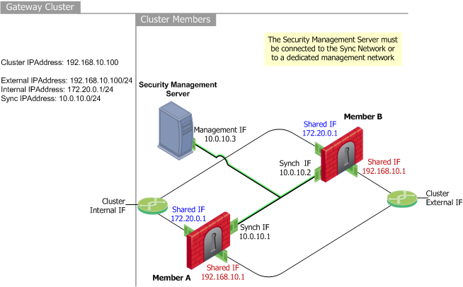
This example shows a typical High Availability Legacy mode deployment. The diagram relates the physical cluster topology to the required SmartDashboard configuration. It shows two cluster members: Member_A (the primary) and Member_B (the secondary) each with three interfaces. One for synchronization, one external shared interface, and one internal shared interface.
Shared Interfaces IP and MAC Address Configuration
With the High Availability Legacy mode, member interfaces connected to the same network (internal, external, DMZ, etc.) share common IP and MAC addresses. Each shared interface on cluster members connects to the appropriate network via a hub or switch.
Only one cluster member is active at any given time. Therefore, the outside world can see only the shared interfaces on one member at any given time.
In the above example deployment, the external interface (facing the Internet) uses the shared IP address 192.168.0.1 for both Member A and Member B. The internal interface (facing the local network) uses IP address 172.20.10.1 for both Member A and Member B.
The Synchronization Interface
State Synchronization between cluster members ensures that existing connections handled by the failed member are maintained during and after failover. The synchronization network passes connection synchronization and other state information between cluster members. Since this network carries sensitive security policy information, it is essential that this connection is secure. You can define more than one synchronization network for backup purposes.
To secure synchronization interfaces, they should be directly connected by a cross-cable, or in the case of three or more cluster members, by means of a dedicated hub, switch, or VLAN.
High Availability cluster members do not have to be synchronized. However, if they are not synchronized, active connections may be lost during failover.
Planning Considerations
IP Address Migration
Legacy mode deployments can be easily migrated from an existing stand-alone gateway configuration to a High Availability cluster. In such cases, we recommend that you assign the existing interfaces IP addresses on your stand-alone Security Gateway as the cluster addresses when feasible. Doing so will avoid altering current IPSec endpoint identities, and in many cases, will make it unnecessary to change Hide NAT configurations.
Security Management server Location
The Security Management server downloads Security Policies to all cluster members. The Security Management server cannot be connected to any network that connects to member shared interfaces, because these interfaces are configured to use the same IP and MAC addresses.
The Security Management server must connect to the cluster synchronization network or a to dedicated management network, because the members will have unique IP addresses.
Routing Configuration
Configure routing so that external network and internal networks are routable to each other.
For example, the sample deployment shows routing configuration as follows:
- Internal networks are defined using 172.20.0.1 as the default gateway.
- The external router is configured with a static route such that network 172.20.0.1 is reached via 192.168.10.1.
Switch (Layer 2 Forwarding) Considerations
The Cluster Control Protocol (CCP) makes use of layer two multicast. In keeping with multicast standards, this multicast address is used only as the destination, and is used in all CCP packets sent on "non-secured" interfaces.
A Layer 2 switch connected to non-secured interfaces, must be capable of forwarding multicast packets to switch ports, or within a VLAN, if it is a VLAN switch. It is acceptable that the switch forward such traffic to all ports, or to ports within the given VLAN. However, it is considered more efficient to forward to only those ports connecting cluster members.
Most switches support multicast by default. Please check your switch documentation for details.
If the connecting switch is incapable of forwarding multicast, CCP can be changed to use broadcast instead.
To toggle between these two modes:
Use the command: 'cphaconf set_ccp broadcast/multicast'
Configuring High Availability Legacy Mode
- Obtain and install a ClusterXL central license on your Security Management server.
- Disconnect the Security Gateways that are to become cluster members from switches and/or hubs.
- Assign the same IP addresses to the shared interfaces on each member. To avoid network conflicts due to sharing MAC addresses, define the IP addresses before physically connecting members to the cluster topology.
- Install and configure Check Point Security Gateway on all cluster members. Each member must use the identical version and build. See the R76 Installation and Upgrade Guide.
Do not reboot the members at this time.
- Connect (or reconnect) the members to their switches and hubs. Make sure that you connect each interface to the appropriate physical network port. Connect each network (internal, external, Synchronization, DMZ, etc.) to a separate VLAN, switch or hub. No special switch configuration is required.
Routing Configuration
- Configure routing so that communication with the networks on the internal side of the cluster is via the cluster IP address on the external side of the cluster. For example, in the sample deployment, the external router is configured as a static route such that network 10.255.255.100 is reached via 192.168.10.100.
- Configure routing so that communication with the networks on the external side of the cluster is via the cluster IP address on the internal side of the cluster. For example, in the sample deployment, the internal router ports are configured with 10.255.255.100 as the default gateway.
- Reboot the members. MAC address configuration will take place automatically.
SmartDashboard Configuration
- In the Network Objects tree, right-click Check Point and then select Security Cluster.
- In the Security Gateway Cluster Creation window, select Classic Mode.=
- In the Cluster Members page, click Add > New Cluster Member to add cluster members to the cluster. Cluster members exist solely inside the Gateway Cluster object. For each cluster member:
- In the Cluster Members Properties window General tab, define a Name and IP Address. Choose an IP address that is routable from the Security Management server so that the Security Policy installation will be successful. This can be an internal or an external address, or a dedicated management interface.
- Click Communication, and Initialize Secure Internal Communication (SIC).
- Define the NAT and VPN tabs, as required.
- You can also add an existing gateway as a cluster member by selecting Add > Add Gateway to Cluster in the Cluster Members page and selecting the gateway from the list in the Add Gateway to Cluster window.
- If you want to remove a gateway from the cluster, click Remove in the Cluster Members page and select Detach Member from Cluster or right-click on the cluster member in the Network Objects tree and select Detach from Cluster.
- In the ClusterXL page,
- Check High Availability Legacy Mode,
- Choose whether to Use State Synchronization. This option is checked by default. If you clear this option, the cluster members will not be synchronized, and existing connections on the failed gateway will be closed when failover occurs.
- Specify the action Upon Gateway Recovery (see What Happens When a Gateway Recovers? for additional information).
- Define the Fail-over Tracking method.
- In the Topology page, define the cluster member addresses. Do not define any virtual cluster interfaces. If converting from another cluster mode, the virtual cluster interface definitions are deleted. In the Edit Topology window:
- Define the topology for each cluster member interface. To automatically read all the predefined settings on the member interfaces, click Get all members' topology.
- In the Cluster column, define the purpose of the network by choosing one of the options from the drop-down list. Define the interfaces with shared IP addresses as belonging to a Monitored Private network, and define one (or more) interfaces of each cluster member as synchronization interface in a synchronization network (1st Sync/2nd Sync/3rd Sync). The options are explained in the Online Help. To define a new network, click Add Network.
- Define the other pages in the Gateway Cluster object as required (NAT, VPN, Remote Access, etc.).
- Install the Security Policy on the cluster.
- Reboot all the cluster members in order to activate the MAC address configuration on the cluster members.
Configuring General Properties
To configure the general properties of a cluster:
- Enter a unique name for this cluster object in the designated field.
- Enter the main cluster IP address.
- Select ClusterXL as a product installed on the cluster.
- Enable ClusterXL and other Network Security Software Blades as appropriate.
Defining Cluster Members
To configure a cluster member:
- On the Cluster Members page, click Add > New Cluster Member.
- In the Cluster Members Properties window General tab, enter a member Name and a physical IP Address, which must be routable from the Security Management server. This can be an internal or an external address, or a dedicated management interface.
- Click Communication, and initialize Secure Internal Communication (SIC) trust.
- Configure NAT and VPN settings on the appropriate tabs as required. For more details, refer to the R76 Security Management Administration Guide.
Adding an Existing Gateway as a Member
To add an existing gateway as a cluster member, select Add > Add Gateway to Cluster on the Cluster Members page and select a gateway from the list in the Add Gateway to Cluster window.
Removing a Member
To remove a gateway from the cluster, click Remove in the Cluster Members page and select Detach Member from Cluster or right-click on the cluster member in the Network Objects tree and select Detach from Cluster.
Configuring ClusterXL Properties
To configure ClusterXL properties for the legacy mode:
- Enable the High Availability option and select the Legacy mode.
- Select the action to perform upon primary member recovery:
- Maintain the current active cluster member
- Switch back to a higher priority cluster member
- For High Availability New deployments, State Synchronization is optional, but enabled by default. If you choose to disable State Synchronization, cluster members do not synchronize, and existing connections on the failed gateway will be terminated once failover occurs.
- Select tracking options from the list.
Completing the Definition
- Define the other pages in the cluster object as required (NAT, VPN, Remote Access, and so on).
- Install a Security Policy on the cluster.
Moving from High Availability Legacy with Minimal Effort
This procedure describes how to move from High Availability Legacy mode to Load Sharing Multicast mode or to High Availability New mode, when the consideration is simplicity of configuration, rather than the minimal downtime.
The shared internal and external interfaces become cluster interfaces. The general IP address of the cluster therefore stays as an external cluster IP address.
On the Gateways
- Run cpstop on all members (all network connectivity will be lost).
- Reconfigure the IP addresses on all the cluster members, so that unique IP addresses are used instead of shared (duplicate) IP addresses.

|
Note - SecurePlatform only: These address changes delete any existing static routes. Copy them down for restoration in step 4
|
- Remove the shared MAC addresses by executing the command:
cphaconf uninstall_macs - SecurePlatform cluster members only: Redefine the static routes deleted in step 2.
- Reboot the members.
From SmartDashboard
In SmartDashboard, open the cluster object, select the ClusterXL tab, change the cluster mode from Legacy mode to new mode or to Load sharing mode. Then follow the Check Point Gateway Cluster Wizard. For manual configuration, proceed as follows:
- In the Topology tab of the cluster object,
- For each cluster member, get the interfaces which have changed since the IP addresses were changed. The interfaces which were previously shared interfaces should now be defined as Cluster interfaces.
- Define the cluster IP addresses of the cluster. The cluster interfaces' names may be defined as you wish as they will be bound to physical interfaces according to the IP addresses.
If the new IP addresses of the cluster members on a specific interface reside on a different subnet than the cluster IP address in this direction, the cluster members' network should be defined in the Members Network fields of the cluster interface (Configuring Cluster Addresses on Different Subnets).
- Install the policy on the new cluster object (Security policy, QOS policy and so on).
Moving from High Availability Legacy with Minimal Downtime
This procedure describes how to move from Legacy Check Point High Availability to New Check Point High Availability or to Load Sharing while minimizing the downtime of the cluster.
The shared internal and external interfaces become the cluster interfaces. As the cluster members will need additional IP addresses these must be prepared in advance.
If downtime of the cluster during the change is not a major issue, it is recommended to use the easier process described in Moving from High Availability Legacy with Minimal Effort.
|
Note - 1. Make sure that you have all the IP addresses needed before you start implementing the changes described here.
2. Backup your configuration before starting this procedure, because this procedure deletes and recreates the objects in SmartDashboard.
|
In this procedure we use the example of machines 'A' and 'B', with the starting point being that machine 'A' is active, and machine 'B' is on standby.
- Disconnect machine 'B' from all interfaces except the interface connecting it to the Security Management server (the management interface).
- Run cphastop on machine 'B'.
- Change the IP addresses of machine 'B' (as required by the new configuration).
|
Note - SecurePlatform only: These address changes delete any existing static routes. Copy them down for restoration in step 5.
|
- Reset the MAC addresses on machine 'B' by executing cphaconf uninstall_macs. The Windows machine must be rebooted for the MAC address change to take effect.
- SecurePlatform cluster members only: Redefine the static routes deleted in step 3.
- In SmartDashboard, right-click member 'A' and select Detach from cluster.
- In the Topology tab of the Cluster Member Properties window, define the topology of cluster member 'B' by clicking Get. Make sure to mark the appropriate interfaces as Cluster Interfaces.
- In the Cluster Object, define the new topology of the cluster (define the cluster interfaces in the cluster's Topology tab).
- In the ClusterXL page, change the cluster's High Availability mode from Legacy Mode to New Mode or select Load Sharing mode.
- Verify that the other pages in the Cluster Object (NAT, VPN, Remote Access and so on) are correct. In Legacy Check Point High Availability, the definitions were per cluster member, while now they are on the cluster itself.
- Install the policy on the cluster, which now only comprises cluster member 'B'.
- Reconnect machine 'B' (which you disconnected in step 1) to the networks.
- In this example the cluster comprises only two members, but if the cluster comprises more than two members, repeat steps 1-9 for each cluster member.
- For Load Sharing Multicast mode, configure the routers.
- Disconnect machine 'A' from the all networks accept the management network. The cluster stops processing traffic.
- Run cphastop on machine 'A'.
- Run cpstop and then cpstart on machine 'B' (if there are more than two machines, run these commands on all machines except 'A').
- Machine 'B' now becomes active and starts processing traffic.
- Change the IP addresses of machine 'A' (as required by the new configuration).
- Reset the MAC addresses of machine 'A' by executing cphaconf uninstall_macs. The Windows machine must be rebooted for the MAC address change to take effect.
- In SmartDashboard, open the Cluster Object and select the Cluster Members page. Click Add > Add Gateway to Cluster and select member 'A' to re-attach it to the cluster.
- Reconnect machine 'A' to the networks from which it was disconnected in step 15.
- Install the security policy on the cluster.
- Run cpstop and then cpstart on machine 'A'.
- Redefine static routes
The cluster now operates in the new mode.
ClusterXL Sync Network Configuration
When connecting the members of a cluster to the sync network:
- If the cluster has only two members, connect the sync ports with a cross cable or straight cable
- For more than two members, connect the sync ports through a switch.
Greater redundancy
For greater redundancy, Check Point recommends using:
- Sync over Bond HA. Connect the sync bond interface of each member to the same switch or VLAN.
- An isolated secured network segment for the Sync network.
|
|
