ClusterXL Advanced Configuration
Working with VPNs and Clusters
Configuring VPN and Clusters
Configuring a Security Gateway cluster using SmartDashboard is very similar to configuring a single Security Gateway. All attributes of the VPN are defined in the Gateway Cluster object, except for two attributes that are defined per cluster member.
- Go to the Gateway Cluster Properties window, Cluster Members page. For each cluster member, in the Cluster member Properties window, configure the VPN tab:
- Office Mode for Remote access — If you wish to use Office Mode for remote access, define the IP pool allocated to each cluster member.
- Hardware Certificate Storage List — If your cluster member supports hardware storage for IKE certificates, define the certificate properties. In that case, Security Management server directs the cluster member to create the keys and supply only the required material for creation of the certificate request. The certificate is downloaded to the cluster member during policy installation.
- In a VPN cluster, IKE keys are synchronized. In the Synchronization page of the Gateway Cluster Properties window, make sure that Use State Synchronization is selected, even for High Availability configurations.
- In the Topology page of the Gateway Cluster Properties window, define the encryption domain of the cluster. Under VPN Domain, choose one of the two possible settings:
- All IP addresses behind cluster members based on topology information. This is the default option.
- Manually Defined. Use this option if the cluster IP address is not on the member network, in other words, if the cluster virtual IP address is on a different subnet than the cluster member interfaces. In that case, select a network or group of networks, which must include the virtual IP address of the cluster, and the network or group of networks behind the cluster.
Defining VPN Peer Clusters with Separate Security Management Servers
When working with a VPN peer that is a Check Point Gateway cluster, and the VPN peer is managed by a different Security Management server, do NOT define another cluster object. Instead, do the following:
- In the objects tree, Network Objects branch, right click and select New Check Point Externally Managed Gateway.
- In the Topology page, add the external and internal cluster interface addresses of the VPN peer. Do not use the cluster member interface addresses, except in the following cases:
- If the external cluster is of version 4.1, add the IP addresses of the cluster member interfaces.
- If the cluster is an OPSEC certified product (excluding IPSO), you may need to add the IP addresses of the cluster members.
When adding cluster member interface IP addresses, in the interface Topology tab, define the interface as Internal, and the IP Addresses behind this interface as Not defined.
- In the VPN Domain section of the page, define the encryption domain of the externally managed gateway to be behind the internal virtual IP address of the gateway. If the encryption domain is just one subnet, choose All IP addresses behind cluster members based on topology information. If the encryption domain includes more than one subnet, it must be Manually Defined.
Working with NAT and Clusters
Cluster Fold and Cluster Hide
Network Address Translation (NAT) is a fundamental aspect of the way ClusterXL works.
When a cluster member establishes an outgoing connection towards the Internet, the source address in the outgoing packets, is the physical IP address of the cluster member interface. The source IP address is changed using NAT to that of the external virtual IP address of the cluster. This address translation is called "Cluster Hide".
For OPSEC certified clustering products, this corresponds to the default setting in the 3rd Party Configuration page of the cluster object, of Hide Cluster Members' outgoing traffic behind the Cluster's IP address being checked.
When a client establishes an incoming connection to external (virtual) address of the cluster, ClusterXL changes the destination IP address using NAT to that of the physical external address of one of the cluster members. This address translation is called "Cluster Fold".
For OPSEC certified clustering products, this corresponds to the default setting in the 3rd Party Configuration page of the cluster object, of Forward Cluster's incoming traffic to Cluster Members' IP addresses being checked.
Configuring NAT on the Gateway Cluster
Network Address Translation (NAT) can be performed on a Gateway Cluster, in the same way as it is performed on a Gateway. This NAT is in addition to the automatic "Cluster Fold" and "Cluster Hide" address translations.
To configure NAT, edit the Gateway Cluster object, and in the Gateway Cluster Properties window, select the NAT page. Do NOT configure the NAT tab of the cluster member object.
Configuring NAT on a Cluster Member
It is possible to perform Network Address Translation (NAT) on a non-cluster interface of a cluster member.
A possible scenario for this is if the non-Cluster interface of the cluster member is connected to another (non-cluster) internal Security Gateway, and you wish to hide the address of the non-Cluster interface of the cluster member.
Performing this NAT means that when a packet originates behind or on the non-Cluster interface of the cluster member, and is sent to a host on the other side of the internal Security Gateway, the source address of the packet will be translated.
To configure NAT on a non-cluster interface of a cluster member gateway:
- Edit the Gateway Cluster object.
- In the Cluster Member page of the Gateway Cluster Properties window, edit the Cluster Member object.
- In the Cluster Member Properties window, click the NAT tab.
- Configure Static or Hide NAT as desired.
Working with VLANS and Clusters
VLAN Support in ClusterXL
A VLAN switch tags packets that originate in a VLAN with a four-byte header that specifies which switch port it came from. No packet is allowed to go from a switch port in one VLAN to a switch port in another VLAN, apart from ports ("global" ports) that are defined so that they belong to all the VLANs.
The cluster member is connected to the global port of the VLAN switch, and this logically divides a single physical port into many VLAN ports each associated with a VLAN tagged interface (VLAN interface) on the cluster member.
When defining VLAN tags on an interface, cluster IP addresses can be defined only on the VLAN interfaces (the tagged interfaces). Defining a cluster IP address on a physical interface that has VLANs is not supported. This physical interface has to be defined with the Network Objective Monitored Private.

|
Note - ClusterXL does not support VLANS on Windows 2000 or Windows 2003 Server.
|
Connecting Several Clusters on the Same VLAN
It is not recommended to connect the non-secured interfaces (the internal or external cluster interfaces, for example) of multiple clusters to the same VLAN. A separate VLAN, and/or switch is needed for each cluster.
Connecting the secured interfaces (the synchronization interfaces) of multiple clusters is also not recommended for the same reason. Therefore, it is best to connect the secured interfaces of a given cluster via a crossover link when possible, or to an isolated VLAN.
If there is a need to connect the secured or the non-secured interfaces of multiple clusters to the same VLAN you need to make changes to:
- The destination MAC address, to enable communication between the cluster and machines outside the cluster (for ClusterXL Load Sharing Multicast Mode clusters only).
- The source MAC address of the cluster, to enable Cluster Control Protocol communication between cluster members.
Changes to the Destination MAC Address
This section applies to ClusterXL Load Sharing Multicast Mode only.
How the Destination Cluster MAC Address is Assigned in Load Sharing Multicast Mode
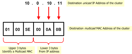
When a machine that is outside the cluster wishes to communicate with the cluster, it sends an ARP query with the cluster (virtual) IP address. The cluster replies to the ARP request with a multicast MAC address, even though the IP address is a unicast address.
This destination multicast MAC address of the cluster is based on the unicast IP address of the cluster. The upper three bytes are 01.00.5E, and they identify a Multicast MAC in the standard way. The lower three bytes are the same as the lower three bytes of the IP address. An example MAC address based on the IP address 10.0.10.11 is shown below.
Duplicate Multicast MAC Addresses: The Problem
When more than one cluster is connected to the same VLAN, the last three bytes of the IP addresses of the cluster interfaces connected to the VLAN must be different. If they are the same, then communication from outside the cluster that is intended for one of the clusters will reach both clusters, which will cause communication problems.
For example, it is OK for the cluster interface of one of the clusters connected to the VLAN to have the address 10.0.10.11, and the cluster interface of a second cluster to have the address 10.0.10.12. However, the following addresses for the interfaces of the first and second clusters will cause complications: 10.0.10.11 and 20.0.10.11.
Duplicate Multicast MAC Addresses: The Solution
The best solution is to change to the last three bytes of the IP address of all but one of the cluster interfaces that share the same last three bytes of their IP address.
If the IP address of the cluster interface cannot be changed, you must change the automatically assigned multicast MAC address of all but one of the clusters and replace it with a user-defined multicast MAC address. Proceed as follows:
- In the ClusterXL page of the cluster object, select Load Sharing>Multicast Mode. In the Topology tab, edit the cluster interface that is connected to same VLAN as the other cluster.
- In the Interface Properties window, General tab, click Advanced.
- Change the default MAC address, and carefully type the new user defined MAC address. It must be of the form 01:00:5e:xy:yy:yy where x is between 0 and 7 and y is between 0 and f(hex).
Changes to the Source MAC Address
This section applies to all ClusterXL modes, both High Availability and Load Sharing, and to OPSEC certified clustering products.
How the Source Cluster MAC Address is Assigned
Cluster members communicate with each other using the Cluster Control Protocol (CCP). CCP packets are distinguished from ordinary network traffic by giving CCP packets a unique source MAC address.
- The first four bytes of the source MAC address are all zero: 00.00.00.00
- The fifth byte of the source MAC address is a magic number. Its value indicates its purpose
Default value of fifth byte
|
Purpose
|
0xfe
|
CCP traffic
|
0xfd
|
Forwarding layer traffic
|
- The sixth byte is the ID of the sending cluster member
Duplicate Source Cluster MAC Addresses: The Problem
When more than one cluster is connected to the same VLAN, if CCP and Forwarding Layer traffic uses Multicast MAC address for the destination, this traffic reaches only the intended cluster.
However, if Broadcast MAC address is used for Destination for CCP and for Forwarding Layer traffic (and in certain other cases), cluster traffic intended for one cluster is seen by all connected clusters. If this traffic is processed by the wrong cluster, it will cause communication problems.
Duplicate Source Cluster MAC Addresses: The Solution
To ensure that the source MAC address in packets from different clusters that are connected to the same VLAN can be distinguished, change the MAC source address of the cluster interface that is connected to the VLAN in all but one of the clusters.
Use the following gateway configuration parameters to set more than one cluster on the same VLAN. These parameters apply to both ClusterXL and OPSEC certified clustering products.
Parameter
|
Default value
|
fwha_mac_magic
|
0xfe
|
fwha_mac_forward_magic
|
0xfd
|
Changing the values of these gateway configuration parameters alters the fifth part of the source MAC address of Cluster Control Protocol and forwarded packets. Use any value as long as the two gateway configuration parameters are different. To avoid confusion, do not use the value 0x00.
For instruction about how to change these parameters, see How to Configure Gateway Configuration Parameters.
Monitoring the Interface Link State
Enabling Interface Link State Monitoring shortens the time it takes for ClusterXL to detect an interface failure. By monitoring the link state (i.e. the electrical state) of an interface, ClusterXL is immediately alerted to connectivity issues concerning a certain network interface, such as a disconnected cable, or an electrical failure (real or simulated) on a switch.
Interface Link State Monitoring requires an interface device driver that supports link state detection. The device driver reports the link state as either connected or disconnected.
Monitoring the interface link state is particularly useful in scenarios where a monitored interface (either a cluster interface or a monitored private interface) sends ICMP ECHO probe requests which are not answered by hosts or routers on the connected subnet.
When enabled, ClusterXL immediately detects when an interface goes down. When disabled, ClusterXL determines whether an interface is malfunctioning by watching subsecond timeout expiration.
Monitoring Interface Link State is disabled by default.
|
Note - Interface Link State Monitoring requires an interface device driver that supports link state detection, and is supported on Linux and SecurePlatform only. This feature only works in two-member ClusterXL clusters where two interfaces are connected directly with a cross-cable. See sk31336.
|
Enabling Interface Link State Monitoring
To enable (or disable) Interface Link State Monitoring:
- Set the global parameter fwha_monitor_if_link_state.
Usage:
fw ctl set int fwha_monitor_if_link_state <0|1>
|
Options:
- 0 – disables Interface Link State Monitoring. This is the default setting.
- 1 – enables Interface Link State Monitoring
For instructions on how to make these configuration parameters survive reboot, see SecureKnowledge sk26202.
Configuring IPv6 Clusters
To enable IPv6 functionality for an interface, define an IPv6 address for the applicable interface on the cluster and on each member. All interfaces configured with an IPv6 address must also have a corresponding IPv4 address. If an interface does not require IPv6, only the IPv4 definition address is necessary.
|
Note - You must configure synchronization interfaces with an IPv4 address only. This is because the synchronization mechanism works using IPv4 only. All IPv6 information and states are synchronized using this interface.
|
To configure IPv6 addresses for cluster interfaces and cluster members:
- In SmartDashboard, create a new cluster object or double-click an existing cluster object.
- Click in the navigation tree.
- Select .
- Click >.
The window opens.
- Click .
- Enter the cluster interface and member information in the applicable fields (IPv4 address, Net Mask, IPv6 address, Prefix length).
To enter information, select the cell and click .
|
Note - Cluster members must have the same IPv6 address prefix as the cluster interface. Different prefixes are not supported.
|
- Click to save your changes.
In an IPv6 environment, the cphaprob – a if command shows both the IPv4 and IPv6 addresses of the virtual cluster interfaces:
#cphaprob -a if
Required interfaces: 3
Required secured interfaces: 1
Sync UP sync(secured), multicast
Mgmt UP non sync(non secured), multicast
eth1-02 UP non sync(non secured), multicast
Virtual cluster interfaces: 2
Mgmt 192.168.34.125
2620:0:2a03:16:2:34:0:502
eth1-02 10.34.125.1
125::1
|
The cphaprob stat command shows only IPv4 sync interfaces.
Link Aggregation and Clusters
Overview
Link Aggregation (also known as NIC teaming) involves bonding multiple network interfaces on a Security Gateway. The interface bond supplies high availability in case of interface failure and, in Load Sharing mode, can significantly increase total throughput.
|
Note - Link Aggregation is supported on SecurePlatform, Gaia, and IPSO.
|
In an interface bond, between two and eight interfaces are set to act as a single interface, using the same IP address.
The bond is a virtual interface, defined on the OS, similar to a physical interface. Each physical interface in a bond is called a slave of that bond. Enslaved interfaces do not function independently of the bond.
Link Aggregation can be configured to one of two modes:
- High Availability (Active/Backup) mode - only one interface at a time is active. Upon interface failure, the bond fails over to another interface. Different interfaces of the bond can be connected to different switches, to add switch high availability to interface high availability.
|
Note - Link-state initiated internal bond failover requires a network interface that supports the Media-Independent Interface (MII) standard.
|
- Load Sharing (Active/Active) mode - all interfaces are active, for different connections. Connections are balanced between interfaces according to network layers three and four, and follow either the IEEE 802.3ad standard or XOR. Load Sharing mode has the advantage of increasing throughput, but requires connecting all the interfaces of the bond to one switch.
For Link Aggregation High Availability mode and for Link Aggregation Load Sharing mode:
- The number of bond interfaces that can be defined is limited by the maximum number of interfaces supported by each platform. See the Release Notes for the appropriate Check Point release.
- Up to 8 NICs can be configured in a single High Availability or Load Sharing bond.
Link Aggregation - High Availability Mode
When dealing with mission-critical applications, an enterprise requires its network to be highly available.
Clustering provides redundancy, and thus, high availability, at the gateway level. Without Link Aggregation, redundancy of Network Interface Cards (NICs) or of the switches on either side of the gateway are only possible in a cluster, and only by failover of the gateway to another cluster member.
Simple Redundant Topology
You can have redundancy of gateway clustering without Link Aggregation. If a switch or gateway fails, a High Availability cluster solution provides system redundancy. For example, you can have a redundant system with two synchronized Security Gateway cluster members deployed in a redundant topology.
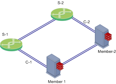
In this scenario:
- GW-1 and GW-2 are cluster members. Each has one external Network Interface Card (NIC) connected to an external switch (S-1 and S-2, respectively).
- S-1 and S-2 are switches
- C-1 and C-2 are interconnecting networks
If Member 1, its NIC, or S-1 fails, Member 2 becomes the only active gateway, connecting to switch S-2 over network C-2. If any component fails (gateway, NIC, or switch), the result of the failover is that no further redundancy exists. A further failure of any active component completely stops network traffic.
Link Aggregation provides high availability of NICs. If one fails, the other can function in its place. This functionality is in High Availability mode and in Load Sharing mode.
Fully Meshed Redundancy
The Link Aggregation High Availability mode, when deployed with ClusterXL, enables a higher level of reliability by providing granular redundancy in the network. This granular redundancy is achieved by using a fully meshed topology, which provides for independent backups for both NICs and switches.
A fully meshed topology further enhances the redundancy in the system by providing a backup to both the interface and the switch, essentially backing up the cable. Each cluster member has two external interfaces, one connected to each switch.
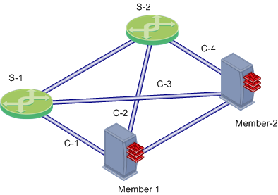
In this scenario:
- Member-1 and Member-2 are cluster members in the High Availability mode, each connected to the two external switches.
- S-1 and S-2 are switches
- C-1, C-2, C-3 and C-4 are network connections
Bond Failover
In Link Aggregation High Availability mode, when the gateway is part of a cluster, bond internal failover can occur in one of these cases:
- An active interface detects a failure in the link state, in a monitored interface.
- ClusterXL detects a failure in sending or receiving Cluster Control Protocol (CCP) keep-alive packets.
Either of these failures will induce a failover within the interface bond, or between cluster members, depending on the circumstances. The section below describes the two types of failover processes.
When a failure is detected, a log is recorded. You can see it in SmartView Tracker.
Creating an Interface Bond in High Availability Mode
Removing IP Addresses from Slave Interfaces
Before you define an interface bond, make sure the slave (physical) interfaces do not have IP addresses:
- Start the SecurePlatform configuration utility:
sysconfig
- Select
Network Connections. - For each interface to be enslaved:
- Select
Configure connection. - Select the relevant physical interface.
- Select
Remove IP from interface. - Return to Network Connections.
- Exit the SecurePlatform configuration utility.
Setting Slave Interfaces as Disconnected
Disconnected interfaces are cluster member interfaces that are not monitored by the ClusterXL mechanism. If a disconnected interface fails, failover does not occur.
To define a slave interface as disconnected in SecurePlatform:
- In $FWDIR/conf/ create a file with this name:
discntd.if - On separate lines in the file, enter the name of each physical interface that will function as a slave/bond pair.
Defining the Interface Bond
When the slave interfaces are without IP addresses, define the bond:
- Start the SecurePlatform configuration utility:
sysconfig
- Select
Network Connections. - Select
Add new connection. - Select
Bond. - For each interface to be enslaved under the bond, type its number in the list, and press Enter.
- Enter
n to go to the next step. - Select
High Availability. - Choose whether to use default parameters (recommended) or to customize them.
- Choose whether to set a primary slave interface, or not (recommended).
A primary slave interface, after failing and coming back up, automatically returns to Active status, even if failover to the other interface occurred. If there is no primary interface, failover causes the other interface to become active and remain so until it fails.
- Define the IP address and network mask of the new interface bond.
- Exit the SecurePlatform configuration utility.
Verifying that the Bond is Functioning Properly
After installation or failover, it is recommended to verify that the bond is up, by displaying bond information.
- Run:
cphaprob -a if
Make sure that the bond status is reported as UP.
- Run:
cphaconf show_bond <bond name>
Check that the bond is correctly configured.
Failover Support for VLANs
In Link Aggregation High Availability mode, ClusterXL monitors VLAN IDs for connectivity failure or miscommunication, and initiate a failover when a failure is detected.
In a VLAN-enabled switched environment, ClusterXL monitors the VLAN with the lowest ID number. The monitoring is conducted by sending ClusterXL Control Protocol (CCP) packets on round-trip paths at a set interval. The lowest VLAN ID indicates the status of the physical connection. This VLAN ID is always monitored, and a connectivity failure causes ClusterXL to initiate a failover. ClusterXL will not detect a VLAN configuration problem on the switch.
Link Aggregation - Load Sharing Mode
In Load Sharing mode, Link Aggregation supplies load sharing, in addition to High Availability. All slave interfaces are active, and connections are balanced between the bond's slave interfaces, similar to the way ClusterXL balances connections between cluster members.
In Load Sharing mode, each connection is assigned to a specific slave interface. For the individual connection, only one slave interface is active. On failure of that interface, the bond does failover of the connection to one of the other interfaces, which adds the failed interface's connection to the connections it is already handling.
Connections are balanced between slave interfaces according to network layers three and four, and follow one of these standards:
- 802.3ad - includes LACP and is the recommended mode, but some switches may not support this mode.
- XOR.
In Load Sharing mode, all the interfaces of a bond must be connected to the same switch. The switch itself must support and be configured for Link Aggregation, by the same standard (802.3ad or XOR) as the gateway bond.
Load Sharing needs Performance Pack to be running.
Workflow of Interface Bond in Load Sharing Mode
Creating a Load Sharing bond is similar to creating a High Availability bond. The procedures for removing IP addresses from slaves, disconnecting slave interfaces, and verifying the bond are the same.
To create a Load Sharing bond:
- Make sure the switches are configured for the standard you are using (802.3ad or XOR).
- Removing IP Addresses from Slave Interfaces
- Setting Slave Interfaces as Disconnected
- Defining Interface Bond in Load Sharing Mode
- Setting Critical Required Interfaces
- Verifying that the Bond is Functioning Properly
Defining Interface Bond in Load Sharing Mode
To define the interface bond:
- Start the SecurePlatform configuration utility:
sysconfig
- Select
Network Connections. - Select
Add new connection. - Select
Bond. - For each interface to be enslaved under the bond, type its number in the list, and press Enter.
- Enter
n to go to the next step. - Select
Load Sharing. - Choose the Load Sharing standard: 802.3ad or XOR.
- Choose whether to use default parameters (recommended) or to customize them.
- Define the IP address and network mask of the new interface bond.
- Exit the SecurePlatform configuration utility.
Setting Critical Required Interfaces
A bond in Load Sharing mode is considered to be down when fewer than a critical minimum number of slave interfaces remain up.
When not explicitly defined, the critical minimum number of interfaces in a bond of n interfaces is n-1. Failure of a second interface will cause the entire bond to be considered down, even if the bond contains more than two interfaces.
If a smaller number of interfaces will be able to handle the expected traffic, you can increase redundancy by explicitly defining the number of critical interfaces. Divide your maximal expected traffic speed by the speed of your interfaces and round up to a whole number to determine an appropriate number of critical interfaces.
To explicitly define the number of critical interfaces, create and edit the following file:
$FWDIR/conf/cpha_bond_ls_config.conf
Each line of the file should be of the following syntax:
<bondname> <critical#>
For example, if bond0 has seven interfaces and bond1 has six interfaces, file contents could be:
bond0 5
bond1 3
In this case bond0 would be considered down when three of its interfaces have failed. bond1 would be considered down when four of its interfaces have failed.
Configuring Cisco Switches for Load Sharing
These are sample configuration commands for Cisco switches.
For 802.3ad:
Switch#conf t
Switch(config)#port-channel load-balance src-dst-ip
Switch(config)#interface FastEthernet <all the participating interfaces>
Switch(config-if)#channel-group 1 mode active
Switch(config-if)#channel-protocol lacp
Switch(config-if)#exit
Switch(config)#interface port-channel 1
Switch(config-if)#switchport access vlan <the wanted vlan number>
Switch(config-if)#end
Switch#write
|
For XOR:
Switch#conf t
Switch(config)#port-channel load-balance src-dst-ip
Switch(config)#interface FastEthernet <all the participating interfaces>
Switch(config-if)#channel-group 1 mode on
Switch(config-if)#exit
Switch (config)#interface port-channel 1
Switch(config-if)#switchport access vlan <the wanted vlan number>
Switch(config-if)#end
Switch#write
|
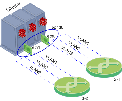
Defining VLANs on an Interface Bond
VLANs can be defined on an interface bond in the same way as on a regular interface.
To define a VLAN on an interface bond:
- Start the SecurePlatform configuration utility:
sysconfig
- Select
Network Connections. - Select
Add new connection. - Select
VLAN. - Select the interface or interface bond on which to define the VLAN.
- Enter a VLAN ID.
- Define the IP addresses for the VLAN.
- Exit the SecurePlatform configuration utility.
Performance Guidelines for Link Aggregation
To get the best performance, use static affinity for Link Aggregation.
Setting Affinities
If you are running Performance Pack in a multi-core system, after you define bonds, set affinities manually. Use the -s parameter of the sim affinity command, see the R76 Performance Tuning Administration Guide.
|
Note - sim affinity commands take effect only if the Performance Pack is enabled and actually running. Performance Pack begins running when you install a policy for the first time.
|
For optimal performance, set affinities according to the following guidelines:
- Run
sim affinity using the -s option. - Whenever possible, dedicate one processing core to each interface. See sk33520.
- If there are more interfaces than cores, one or more cores handle two interfaces. Use interface pairs of the same position with internal and external bonds.
- To view interface positions in a bond, run:
cat /proc/net/bonding/<bond name>.
- Note the sequence of the interfaces in the output, and compare this for the two bonds (external bond and its respective internal bond). Interfaces that appear in the same position in the two bonds are interface pairs and set to be handled by one processing core.
For example, you might have four processing cores (0-3) and six interfaces (0-5), distributed among two bonds:
bond0
|
bond1
|
eth0
|
eth3
|
eth1
|
eth4
|
eth2
|
eth5
|
Two of the cores will need to handle two interfaces each. An optimal configuration might be:
bond0
|
|
bond1
|
|
eth0
|
core 0
|
eth3
|
core 0
|
eth1
|
core 1
|
eth4
|
core 1
|
eth2
|
core 2
|
|
|
|
|
eth5
|
core 3
|
ClusterXL Commands for Interface Bonds
cphaconf show_bond
|
See status of one interface bond or summary of all bonds
|
Syntax
|
cphaconf show_bond [<bond-name>|-a]
|
Options
|
Parameter
|
Description
|
bond-name
|
name of target bond
|
-a
|
show summary of all bonds
|
|
|
Example
|
[Expert@GW-1]# cphaconf show_bond bond0
Bond name: bond0
Bond mode: Load Sharing
Bond status: Up
Balancing mode: 802.3ad Layer3+4 Load Balancing
Configured slave interfaces: 4
In use slave interfaces: 4
Required slave interfaces: 2
Slave Name | Status | Link
--------------------------------------------
eth2 | Active | Yes
eth3 | Active | Yes
eth4 | Active | Yes
eth5 | Active | Yes
|
Comments
|
The report results show:
- Required slave interfaces
- Status value:
- Down - (Load Sharing only) the physical link is down.
- Active - currently handling traffic.
- Standby - (High Availability only) the interface is ready and can support internal bond failover.
- Not Available - (High Availability only) the physical link is broken, or the Cluster member is in status down. The bond cannot failover in this state.
- Link - if the physical link exists.
|
cphaconf failover_bond
|
Starts interface bond internal failover (High Availability only)
|
Syntax
|
cphaconf failover_bond <bond-name>
|
Parameters
|
Parameter
|
Description
|
bond-name
|
name of target bond
|
|
|
chaprob -a if
|
Displays status of all interface bonds and VLANs
|
Syntax
|
cphaprob -a if
|
Example
|
[Expert@GW-1]# cphaprob -a if
Required interfaces: 5
Required secured interfaces: 1
bond0 UP non sync(non secured), broadcast, bond, can failover
bond2 UP sync(secured), multicast, bond Load Sharing
bond1 UP non sync(non secured), multicast, bond Load Sharing
Virtual cluster interfaces: 4
bond0 192.168.34.60
bond1.60 10.34.60.1
bond1.61 10.34.61.1
bond1.62 10.34.62.1
|
Comments
|
Use this command to see if a High Availability bond can failover.
|
Troubleshooting Bonded Interfaces
Troubleshooting Workflow
- Check the status of the bond.
- If there is a problem, see if the physical link is down:
- Run:
cphaconf show_bond <bond-name>
- Look for a slave interface that reports the status of the link as no.
- Check the cable connections and other hardware.
- Check the port configuration on the switch.
- See if a cluster member is down:
cphaprob state
If any of the cluster members have a Firewall State other than active, continue with the cphaprob state troubleshooting.
- View the logs in SmartView Tracker.
Connectivity Delays on Switches
When using certain switches, connectivity delays may occur during some internal bond failovers. With the various features that are now included on some switches, it can take close to a minute for a switch to begin servicing a newly connected interface. These are suggestions for reducing the startup time after link failure.
- Disable autonegotiation on the relevant interface.
- On some Cisco switches, enable the PortFast feature.
- Disable STP on the ports.
Warnings Regarding Use of PortFast
The PortFast feature should never be used on ports that connect to other switches or hubs. It is important that the Spanning Tree complete the initialization procedure in these situations. Otherwise, these connections may cause physical loops where packets are continuously forwarded (or even multiply) in such a way that network will ultimately crash.
Sample Configuration of PortFast Feature on a Cisco Switch
The following are the commands necessary to enable PortFast on a GigabitEthernet 1/0/15 interface of a Cisco 3750 switch running IOS.
- Enter configuration mode:
cisco-3750A#conf t
- Specify the interface to configure:
cisco-3750A(config)#interface gigabitethernet1/0/15
- Set PortFast on this interface:
cisco-3750A(config-if)#spanning-tree portfast
Advanced Cluster Configuration
How to Configure Gateway Configuration Parameters
A number of synchronization and ClusterXL capabilities are controlled by means of Security Gateway configuration parameters. Run these commands on the Security Gateway as follows:
fw ctl set int Parameter <value>
|
Parameter is any of the parameters described in the following sections.
Changes to their default values must be implemented on all cluster members. Setting different values on cluster members can cause configuration problems and possibly connection failures.
All these gateway configuration parameters can be configured to survive a boot. The way to do this varies with the operating system.
How to Configure Gateway to Survive a Boot
Gateway configuration parameters that are changed using the fw ctl set int command do not survive reboot. The way to do make them survive a reboot varies with the operating system. In the following instructions, Parameter is any of the parameters described in the following sections.
Linux/SecurePlatform
- Edit the file $FWDIR/boot/modules/fwkern.conf.
- Add the line Parameter=<value in hex>.
- Reboot.
Windows
- Edit the registry.
- Add a DWORD value named Parameter under the key HKEY_LOCAL_MACHINE\SYSTEM\CurrentControlSet\Services\FW1\Parameters\Globals.
- Reboot.
Setting Module Variables in IPSO 6.1 and Later
When you install IPSO or run Voyager for the first time on a new platform, the Firewall Kernel Tuning Configuration page does not appear. If a customer service representative instructs you to use this page, you must first display it by performing these steps:
- Establish a command line connection to the platform (using a network connection or console connection).
- At the IPSO shell prompt, enter
# dbset advanced:loader t - Run Voyager (or exit Voyager and run it again if Voyager was open when you entered the previous command).
- Click Configuration > Tools > Firewall Kernel Tuning in the navigation tree.
- Configure the variables as instructed by support and click Apply. Clicking Apply applies the firewall kernel variables and also saves the Voyager configuration so that the Firewall Kernel Tuning Configuration page will appear again if you reboot the platform.
Controlling the Clustering and Synchronization Timers
The following gateway configuration parameters are used to control the clustering and synchronization timers. Changing the default values is not recommended.
Clustering and Synchronization timers
Parameter
|
Meaning
|
Default Value
|
fwha_timer_cpha_res
|
The frequency of ClusterXL operations on the cluster.
Operations occur every:
10 multiplied by fwha_timer_cpha_res multiplied by fwha_timer_base_res milliseconds
|
1
|
fwha_timer_sync_res
|
The frequency of sync flush operations on the cluster.
Operations occur every:
10 multiplied by fwha_timer_sync_res multiplied by fwha_timer_base_res milliseconds
|
1
|
fwha_timer_base_res
|
Must be divisible by 10 with no remainders.
|
10
|
Blocking New Connections Under Load
The reason for blocking new connections is that new connections are the main source of new synchronization traffic, and synchronization may be put at risk if new traffic continues to be processed at this rate.
A related error message is: "FW-1: State synchronization is in risk. Please examine your synchronization network to avoid further problems!".
Reducing the amount of traffic passing through the Security Gateway protects the synchronization mechanism.
- fw_sync_block_new_conns allows Security Gateway to detect heavy loads and start blocking new connections. Load is considered heavy when the synchronization transmit queue of the firewall starts to fill beyond the fw_sync_buffer_threshold.
- To enable load detection, set to 0.
- To disable load detection, set to -1 (0xFFFFFFFF hex) (default value).
Note that blocking new connections when sync is busy is only recommended for Load Sharing ClusterXL deployments. While it is possible to block new connections in High Availability mode, doing so does not solve inconsistencies in sync, as High Availability mode precludes that from happening. This parameter can be set to survive boot using the mechanism described in How to Configure Gateway to Survive a Boot.
- fw_sync_buffer_threshold is the maximum percentage of the buffer that may be filled before new connections are blocked. By default it is set to 80, with a buffer size of 512. By default, if more than 410 consecutive packets are sent without getting an ACK on any one of them, new connections are dropped. When blocking starts, fw_sync_block_new_conns is set to 1. When the situation stabilizes it is set back to 0.
- fw_sync_allowed_protocols is used to determine the type of connections that can be opened while the system is in a blocking state. Thus, the user can have better control over the system's behavior in cases of unusual load. The fw_sync_allowed_protocols variable is a combination of flags, each specifying a different type of connection. The required value of the variable is the result of adding the separate values of these flags. For example, the default value of this variable is 24, which is the sum of TCP_DATA_CONN_ALLOWED (8) and UDP_DATA_CONN_ALLOWED (16), meaning that the default allows only TCP and UDP data connections to be opened under load.
ICMP_CONN_ALLOWED
|
1
|
TCP_CONN_ALLOWED
|
2 (except for data connections)
|
UDP_CONN_ALLOWED
|
4 (except for data connections)
|
TCP_DATA_CONN_ALLOWED
|
8 (the control connection should be established or allowed)
|
UDP_DATA_CONN_ALLOWED
|
16 (the control connection should be established or allowed)
|
Working with SmartView Tracker Active Mode
Active mode in SmartView Tracker shows connections currently open through any of the Security Gateways that are sending logs to the currently active Log File on the Security Management server.
Active mode tends to slow down synchronization. If that happens, the synchronization mechanism randomly drops Active connection updates in order to maintain synchronization. The drop will be accompanied by one of the error message described in SmartView Tracker Active Mode Messages.
Active mode view is not recommended on a heavily loaded cluster. To obtain a more accurate report of Active connections under load, two solutions are available. They apply both to a cluster and to a single Security Gateway:
- Enlarge fwlddist_buf_size
The fwlddist_buf_size parameter controls the size of the synchronization buffer in words. (Words are used for both synchronization and in SmartView Tracker Active mode. 1 word equals 4 Bytes). The default is 16k words. The maximum value is 64k words and the minimum value is 2k words.
If changing this parameter, make sure that it survives boot, because the change is only applied after a reboot. Use the mechanism described in How to Configure Gateway Configuration Parameters.
- Obtain a Hotfix from Technical Support
Obtain a Check Point Technical Support Hotfix. This Hotfix has a variable that controls the rate at which Active connections are read by fwd on the gateway before being sent to the Security Management server Note that this solution requires additional CPU resources.
Reducing the Number of Pending Packets
ClusterXL prevents out-of-state packets in non-sticky connections. It does this by holding packets until a Sync ACK is received from all other active cluster members. If for some reason a Sync ACK is not received, the Security Gateway on the cluster member will not release the packet, and the connection will not be established.
To find out if held packets are not being released, run the fw ctl pstat command. If the output of the command shows that the Number of Pending Packets is large under normal loads (more than 100 pending packets), and this value does not decrease over time, use the fwldbcast_pending_timeout parameter to reduce the number of pending packets.
Change the value of fwldbcast_pending_timeout from the default value of 50 to a value lower than 50.
The value is in ticks units, where each tick is equal to 0.1 sec, so that 50 ticks is 5 seconds.
The value represents the time after which packets are released even if Sync ACKs are not received.
Configuring Full Synchronization Advanced Options
When a cluster member comes up after being rebooted (or after cpstart), it has to perform Full Synchronization. As a first step in the Full Synchronization process, it performs a handshake with one of the other active cluster members. Only if this handshake succeeds does the cluster member continue with the Full Synchronization process.
The extended handshake that takes place (by default) exchanges information between cluster members. This information includes version information, information about the installed Check Point products, and can include information about which the VPN kernel tables are currently active. The extended handshake is unrelated to the exchange of kernel table information that happens later in the Full Synchronization.
All cluster members must have the same Check Point products and versions installed. The extended handshake identifies when different products are installed on the cluster members. When different products are installed, a console warning and a log message are issued.
In order to support backward compatibility, it is possible to change the behavior of the extended handshake by means of the following Gateway Configuration Parameters. How to edit these parameters is explained in Advanced Cluster Configuration:
- fw_sync_no_ld_trans has the default the value of 1. Set to 0 in order to exchange kernel table information between members in the first phase of the Full Synchronization process.
- fw_sync_no_conn_trans has the default value of 0. Set to 1 in order not to exchange installed product information between members in the first phase of the Full Synchronization process.
- fw_sync_fcu_ver_check has the default value of 1. set to 0 to allow Full Connectivity Upgrade for versions that do not comply with requirements specified in the R76 Installation and Upgrade Guide.
Defining Disconnected Interfaces
Disconnected interfaces are cluster member interfaces that are not monitored by the ClusterXL mechanism.
You may wish to define an interface as disconnected if the interface is down for a long time, and you wish the cluster member to continue to be active.
The processes listed below are equivalent to defining a non-monitored interface from the Topology page, with the exception that the GUI method works only for interfaces that have a defined IP address.
Defining a Disconnected Interface on Unix
Create a file under $FWDIR/conf/discntd.if and write the name of each interface that you do not want monitored by ClusterXL on a separate line.
Defining a Disconnected Interface on Windows
- Open the regedt32 registry editor. Do not use regedit.
- Under HKEY_LOCAL_MACHINES\System\CurrentControlSet\Services\CPHA create a new value with the following characteristics:
Value Name : DisconnectedInterfaces
Data Type : REG_MULTI_SZ - Add the interface name. To obtain the interface system name run the command:
fw getifs - Add this name to the list of disconnected interfaces using the following format:
\device\<System Interface Name> - Run cphastop and then cphastart to apply the change.
Configuring Policy Update Timeout
When policy is installed on a Gateway Cluster, the cluster members undertake a negotiation process to make sure all of them have received the same policy before they actually apply it. This negotiation process has a timeout mechanism which makes sure a cluster member does not wait indefinitely for responses from other cluster members, which is useful in cases when another cluster member goes down when policy is being installed (for example).
In configurations on which policy installation takes a long time (usually caused by a policy with a large number of rules), a cluster with more than two machines, and slow machines, this timeout mechanism may expire prematurely.
It is possible to tune the timeout by setting the following parameter:
fwha_policy_update_timeout_factor.
The default value is 1 which should be sufficient for most configurations. For configurations where the situation described above occurs, setting this parameter to 2 should be sufficient. Do NOT set this parameter to a value larger than 3.
Enhanced 3-Way TCP Handshake Enforcement
The standard enforcement for a 3-way handshake that initiates a TCP connection provides adequate security by guaranteeing one-directional stickiness. This means that it ensures that the SYN-ACK will always arrive after the SYN. However, it does not guarantee that the ACK will always arrive after the SYN-ACK, or that the first data packet will arrive after the ACK.
If you wish to have stricter policy that denies all out-of-state packets, you can configure the synchronization mechanism so that all the TCP connection initiation packets arrive in the right sequence (SYN, SYN-ACK, ACK, followed by the data). The price for this extra security is a considerable delay in connection establishment.
To enable enhanced enforcement, use the Database Tool to change the sync_tcp_handshake_mode property from minimal_sync (default value) to complete_sync.
Configuring Cluster Addresses on Different Subnets
Introduction to Cluster Addresses on Different Subnets
Cluster IPs are virtual IP addresses given to ClusterXL objects, which differ from the unique IPs of the individual cluster machines. These addresses enable the cluster to be seen as a single gateway, thus allowing it to serve as a router in a network that is unaware of the cluster's internal structure and status.
In previous versions, cluster IP addresses had to be configured on the same subnets as those used by the unique addresses of the cluster members. Cluster IPs can reside on subnets other than those of the members. The advantage of this is that it
- Enables a multi-machine cluster to replace a single-machine gateway in a pre-configured network, without the need to allocate new addresses to the cluster members.
- Makes it possible to use only one routable address for the ClusterXL Gateway Cluster
|
Note - This capability is available only for ClusterXL Gateway Clusters. For details about OPSEC certified clusters, see the vendor documentation.
|
An important aspect of this is that packets sent from cluster members (as opposed to packets routed through the members) are hidden behind the cluster IP and MAC addresses. The cluster MAC is the:
- MAC of the active machine, in High Availability New mode.
- Multicast MAC, in Load Sharing Multicast mode.
- Pivot member MAC in Load Sharing Unicast mode.
This enables the members to communicate with the surrounding networks, but also has certain limitations, as described in Limitations of Cluster Addresses on Different Subnets.
Configuration of Cluster Addresses on Different Subnets
There are two major steps required in order for ClusterXL to function correctly with cluster IPs on different subnets.
The first step is to create static routes on each cluster member, which determine the interface connected to the cluster's network (the subnet to which the cluster IP belongs). Unless these entries are created, the OS cannot route packets to the cluster's network. No additional configuration is required for the cluster members. It is, however, important to note that the unique IPs given to the members must share common subnets on each "side" of the cluster (meaning, each interface on each machine must have an interface on every other machine using the same subnet).
The second step relates to the configuration of the cluster topology. Here the cluster IPs are determined, and associated with the interfaces of the cluster members (each member must have an interface responding to each cluster IP). Normally, cluster IPs are associated with an interface based on a common subnet. In this case these subnets are not the same. It must be explicitly specified which member subnet is associated with the cluster IP.
To specify the member network:
- Select Topology in the Gateway Cluster Properties Window.
- Click Edit Topology.
- In the Edit Topology window, manually enter the IP address and subnet in the appropriate member interface fields.
Note that this interface actually refers to the cluster's virtual IP address, as determined in the cluster topology.
Example of Cluster Addresses on Different Subnets
In this example, a single-gateway firewall separating network 172.16.6.0 (Side "A") from network 172.16.4.0 (Side "B") is to be replaced with a ClusterXL cluster. The cluster members, however, will use networks 192.168.1.0 for Side "A", 192.168.2.0 for Side "B" and 192.168.3.0 for the synchronization network (all network addresses given in this example are of class "C"). The addresses in italics are the cluster IP addresses. The resulting configuration is depicted below:
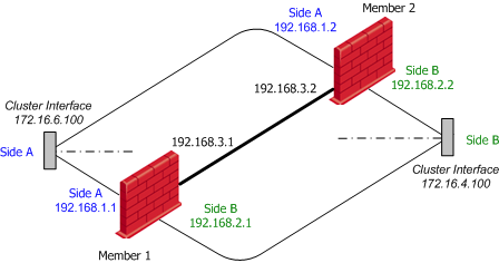
Configuring Static Routes on the Members
Each member should be configured with two static routes:
- One setting its 192.168.1.x IP address as the gateway for network 172.16.6.0
- One setting its 192.168.2.x IP address as the gateway for network 172.16.4.0.
For more on static route configuration, see sk32073.
Configuring Cluster IP Addresses in SmartDashboard
To configure the cluster interface IP addresses:
- In the Gateway cluster object Topology > Edit Topology window, edit a cluster interface, and open the Interface Properties window.
- For each cluster interface, configure the Interface Properties window as follows:
Example ClusterXL Topology > Interface Properties
|
Cluster Interface A
IP address
|
Cluster Interface B
IP address
|
General tab
|
172.16.6.100
|
172.16.4.100
|
Member Networks tab
|
192.168.1.0
|
192.168.2.0
|
- All IP addresses have the Netmask 255.255.255.0
|
Note - Do not define Cluster IP addresses for the synchronization interfaces. The synchronization interfaces are also defined in the Edit Topology page of the Gateway Cluster object.
|
Limitations of Cluster Addresses on Different Subnets
This new feature does not yet support all the capabilities of ClusterXL. Some features require additional configuration to work properly, while others are not supported.
Connectivity Between Cluster Members
Since ARP requests issued by cluster members are hidden behind the cluster IP and MAC, requests sent by one cluster member to the other may be ignored by the destination machine. To allow cluster members to communicate with each other, a static ARP should be configured for each cluster member, stating the MAC addresses of all other machines in the cluster. IP packets sent between members are not altered, and therefore no changes should be made to the routing table.
|
Note - Static ARP is not required in order for the machines to work properly as a cluster, since the cluster synchronization protocol does not rely on ARP.
|
Load Sharing Multicast Mode with "Semi-Supporting" Hardware
Although not all types of network hardware work with multicast MAC addresses, some routers can pass such packets, even though they are unable to handle ARP replies containing a multicast MAC address. Where a router semi-supports Load sharing Multicast mode, it is possible to configure the cluster MAC as a static ARP entry in the router's internal tables, and thus allow it to communicate with the cluster.
When different subnets are used for the cluster IPs, static ARP entries containing the router's MAC need to be configured on each of the cluster members. This is done because this kind of router will not respond to ARP requests containing a multicast source MAC. These special procedures are not required when using routers that fully support multicast MAC addresses.
Manual Proxy ARP
When using static NAT, the cluster can be configured to automatically recognize the hosts hidden behind it, and issue ARP replies with the cluster MAC address, on their behalf. This process is known as Automatic Proxy ARP.
However, if you use different subnets for the cluster IP addresses, this mechanism will not work, and you must configure the proxy ARP manually. To do so, in SmartDashboard, select Policy menu > Global Properties > NAT Network Address Translation, and disable Automatic ARP Configuration. Then create a file called local.arp in the firewall's configuration directory ($FWDIR/conf).
Each entry in this file is a triplet, containing the:
- host address to be published
- MAC address that needs to be associated with the IP address
- unique IP of the interface that responds to the ARP request.
The MAC address that should be used is the cluster's multicast MAC defined on the responding interface, when using multicast LS, or this interface's unique IP, for all other modes.
For example, if host 172.16.4.3 is to be hidden using the address 172.16.6.25, and the cluster uses Load Sharing Multicast mode, add the following line to the local.arp file of Member 1:
172.16.6.25 00:01:5e:10:06:64 192.168.1.1
The second parameter in this line is the multicast MAC address of cluster IP 172.16.6.100, through which ARP requests for 172.16.6.25 will be received. On Member 2, this line will be:
172.16.6.25 00:01:5e:10:06:64 192.168.1.2
If the cluster is in unicast LS mode, or in HA mode, the entries on Member 1 and 2 will be:
172.16.6.25 00:A0:C9:E8:C7:7F 192.168.1.1
- And -
172.16.6.25 00:A0:C9:E8:CB:3D 192.168.1.2
where the second entry in each line is the unique MAC address of the matching local interface.
Connecting to the Cluster Members from the Cluster Network
Since the unique IPs may be chosen arbitrarily, there is no guarantee that these addresses are accessible from the subnet of the cluster IP. In order to access the members through their unique IPs, you must configure routes on the accessing machine, such that the cluster IP is the gateway for the subnet of the unique IPs. Following the above example, 172.16.6.100 should be the gateway for subnet 192.168.1.0.
Default Gateway on SecurePlatform
Run sysconfig > routing > add network route > add the routable network with its subnet, and choose the correct physical interface in this direction.
Now go to routing > add default gateway and add the IP address of the default (routable) gateway. This will usually be the IP address of the router in one of the cluster IP's subnet.
If you have the different subnets feature configured on more than one interface, repeat the addition of the network address (as above) for all these interfaces. (It is NOT required to define a default gateway for the other subnets as well.)
Anti-Spoofing
When the different subnets feature is defined on a non-external interface, the cluster IP in the Cluster Topology tab should not be defined with the Network defined by interface IP and Net Mask definition in the Topology tab of the Interface Properties window of the cluster interface. You must add a group of networks that contain both the routable network and the non-routable network, and define the Anti-spoofing for this interface as specific: network with this new group.
Moving from a Single Gateway to a ClusterXL Cluster
This procedure describes how to add a new gateway (Machine 'B') to a standalone Security Gateway (Machine 'A') to create a cluster.
As a prerequisite, there should be available IP addresses in a quantity equal to the number of new cluster members. If there are not, see: Configuring Cluster Addresses on Different Subnets.
On the Single Gateway Machine
If your single gateway installation uses the same machine for the Security Management server and the gateway:
- Separate the Security Management server from the gateway, and place them on two machines.
- Initialize SIC on the separated gateway (Machine 'A').
On Machine 'B'
- Define an interface on machine 'B' for each proposed cluster interface and synchronization interface on machine 'A', with the same subnet. If the members exist on different subnets, see: Configuring Cluster Addresses on Different Subnets.
- Install the Security Gateway on the machine. During the installation you must enable ClusterXL.
In SmartDashboard, for Machine 'B'
- Create a ClusterXL object.
- In the Cluster Members page, click Add, and select New Cluster Member.
- Connect to machine 'B', and define its topology.
- Define the Synchronization networks for the cluster.
- Define the cluster topology. To avoid reconfiguring network devices, the cluster IP addresses should be the same as the addresses of machine 'A', on its proposed cluster interfaces.
- Install the policy on the cluster, currently including member 'B' only.
On Machine 'A'
- Disconnect all proposed cluster and Synchronization interfaces. New connections now open through the cluster, instead of through machine 'A'.
- Change the addresses of these interfaces to some other unique IP address which is on the same subnet as machine B.
- Connect each pair of interfaces of the same subnet using a dedicated network. Any hosts or gateways previously connected to the single gateway must now be connected to both machines, using a hub/switch.
In SmartDashboard for Machine 'A'
- Update the topology of gateway A, either manually or by clicking Get Topology.
If the IP address of the management interface was changed, the Get Topology action will fail. If this happens, manually change the main IP address in the gateway object and save the policy prior to performing an automatic topology fetch.
- In the Cluster Members page, click Add, and select Add Gateway to Cluster.
- Select machine 'A' in the window.
- In the Edit Topology page, determine which interface is a cluster interface, and which is an internal or an external interface.
- Install the policy on the cluster.
Adding Another Member to an Existing Cluster
- On the cluster member, run cpconfig to enable ClusterXL.
- Change the IP addresses of the new cluster member to reflect the correct topology (either shared IP addresses or unique IP addresses, depending on the clustering solution).
- Ensure that all required Check Point products are installed on the new cluster member.
- In the Cluster Members page of the Gateway Cluster object, either create a new cluster member (if it is a new Security Gateway machine) with the appropriate properties, or convert an existing Gateway to a cluster member.
- If this is a new Security Gateway machine, ensure that SIC is initialized. In the Edit Topology page, ensure that the topology is correctly defined.
- If the Cluster Mode is Load Sharing or New HA, ensure that the proper interfaces on the new cluster member are configured as Cluster Interfaces.
- Install the security policy on the cluster.
- The new member is now part of the cluster.
Configuring ISP Redundancy on a Cluster
If you have a ClusterXL Gateway cluster, connect each cluster member to both ISPs via a LAN using two interfaces. The cluster-specific configuration is illustrated below.
Note that the member interfaces must be on the same subnet as the cluster external interfaces. Configure ClusterXL in the usual way.
Enabling Dynamic Routing Protocols in a Cluster Deployment
ClusterXL supports Dynamic Routing (Unicast and Multicast) protocols as an integral part of SecurePlatform. As the network infrastructure views the clustered gateway as a single logical entity, failure of a cluster member will be transparent to the network infrastructure and will not result in a ripple effect.
Components of the System
Virtual IP Integration
All cluster members use the cluster IP address(es).
Routing Table Synchronization
Routing information is synchronized among the cluster members using the Forwarding Information Base (FIB) Manager process. This is done to prevent traffic interruption in case of failover, and used for Load Sharing and High Availability modes. The FIB Manager is the responsible for the routing information.
The FIB Manager is registered as a critical device (Pnote), and if the slave goes out of sync, a Pnote will be issued, and the slave member will go down until the FIB Manager is synchronized.
Failure Recovery
Dynamic Routing on ClusterXL avoids creating a ripple effect upon failover by informing the neighboring routers that the router has exited a maintenance mode. The neighboring routers then reestablish their relationships to the cluster, without informing the other routers in the network. These restart protocols are widely adopted by all major networking vendors. The following table lists the RFC and drafts compliant with Check Point Dynamic Routing:
Compliant Protocols
Protocol
|
RFC or Draft
|
OSPF LLS
|
draft-ietf-ospf-lls-00
|
OSPF Graceful restart
|
RFC 3623
|
BGP Graceful restart
|
draft-ietf-idr-restart-08
|
Dynamic Routing in ClusterXL
The components listed above function "behind-the-scenes." When configuring Dynamic Routing on ClusterXL, the routing protocols automatically relate to the cluster as they would to a single device.
When configuring the routing protocols on each cluster member, each member is defined identically, and uses the cluster IP address(es) (not the member's physical IP address). In the case of OSPF, the router ID must be defined and identical on each cluster member. When configuring OSPF restart, you must define the restart type as signaled or graceful. For Cisco devices, use type signaled.
Use SecurePlatform's command line interface to configure each cluster member.
Enabling OSPF on cluster member A
--------- Launch the Dynamic Routing Module
[Expert@GWa]# router
localhost>enable
localhost#configure terminal
--------- Enable OSPF and provide an OSPF router ID
localhost(config)#router ospf 1
localhost(config-router-ospf)#router-id 192.168.116.10
localhost(config-router-ospf)#restart-type [graceful | signaled]
localhost(config-router-ospf)#redistribute kernel
--------- Define interfaces/IP addresses on which OSPF runs (Use the cluster IP
address as defined in topology) and the area ID for the interface/IP address
localhost(config-router-ospf)#network 1.1.10.10 0.0.0.0 area 0.0.0.0
localhost(config-router-ospf)#network 1.1.10.20 0.0.0.0 area 0.0.0.0
-------- Exit the Dynamic Routing Module
localhost(config-router-ospf)#exit
localhost(config)#exit
-------- Write configuration to disk
localhost#write memory
IU0 999 Configuration written to '/etc/gated.ami'
|
The same configuration needs to be applied to each cluster member.
As the FIB Manager uses TCP 2010 for routing information synchronization, the Security Policy must accept all traffic on port TCP 2010 between cluster members.
For detailed information regarding Dynamic Routing, see the R76 Advanced Routing Suite CLI Reference guide.
|
