
Mounting the Maestro Orchestrator MHO-175 in a Rack
This section provides the information necessary to mount the Maestro Orchestrator A scalable Network Security System that connects multiple Check Point Security Appliances into a unified system. Synonyms: Orchestrator, Quantum Maestro Orchestrator, Maestro Hyperscale Orchestrator. Acronym: MHO. MHO-175 in a rack.
Installation and Initialization
Installation and initialization of the Maestro Orchestrator See "Maestro Orchestrator". requires attention to the normal mechanical, power, and thermal precautions for rack-mounted equipment.
|
|
Important:
|
The installation procedure for the Maestro Orchestrator involves these phases:
|
Phase |
Instructions |
|---|---|
|
1 |
Make sure that none of the shipping carton contents is missing or damaged. |
|
2 |
Follow the Safety Warnings. |
|
3 |
Pay attention to the airflow consideration within the Maestro Orchestrator and rack. See Airflow in MHO-175. |
|
4 |
Mount the Maestro Orchestrator into a rack enclosure. |
|
5 |
Power on the Maestro Orchestrator. |
Airflow in MHO-175
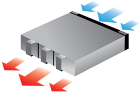
The fan units in the Maestro Orchestrator generate the airflow from the front panel (intake) to the rear panel:
|
|
Important:
|
Static Rail Kit for MHO-175
The Maestro Orchestrators are sold with the static rail kit.
|
|
Important - At least two people are required to mount the Maestro Orchestrator safely in the rack. |
Installation Rail Kit:
|
Rack Size and Rack Depth Range |
Comments |
|---|---|
|
43 - 80 cm (16.9 - 31.4 inches) |
Supplied by default |
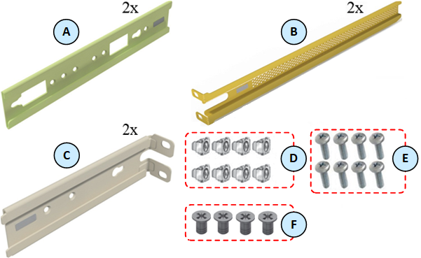
Parts in the static rail kit:
|
Item |
Description |
|---|---|
|
A |
2 x Rack mount rails |
|
B |
2 x Rack mount blades |
|
C |
2 x Rack mount rail ears |
|
D |
8 x M6 standard cage nuts |
|
E |
8 x M6 standard Phillips pan-head screws |
|
F |
4 x Phillips flat-head screws with a round patch, Head 100 Degree, Type I, Size 6-32, Length 1/4 inch |
Notes:
-
You use the Phillips flat head screws (F) to secure the rack mount rails (A) to the Maestro Orchestrator.
-
You use the Phillips flat head screws (F) to secure the rack mount rail ears (C) to the Maestro Orchestrator.
-
You use the cage nuts (D) and Phillips pan-head screws (E) to secure the rack mount rails (A) to the rack.
-
You use the cage nuts (D) and Phillips pan-head screws (E) to secure the rack mount rail ears (C) to the rack.
Before you mount the Maestro Orchestrator to the rack, plan the way you wish to place it:
Pay attention to the airflow within the rack cooling, connector, and cabling options.
While you plan how to place the Maestro Orchestrator, review these points:
-
Make sure the Maestro Orchestrator air flow is compatible with your installation selection.
It is important to keep the airflow within the rack in the same direction.
-
Note that the part of the Maestro Orchestrator, to which you choose to attach the rails, determines the Maestro Orchestrator's adjustable side.
The Maestro Orchestrator's part, to which the blades are attached, should be adjacent to the cabinet.
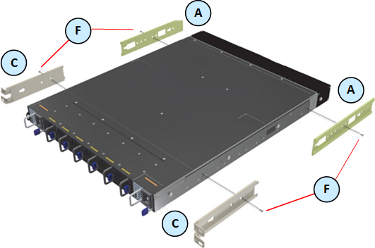
Installation Option 1 - Attaching the mount rail ears (C) near the rear panel

Installation in short racks (43 - 58 cm / 16.9 - 22.8 inches):
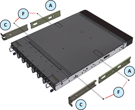


Important - In short racks, the designated windows in the rack mount rails must align with the ventilation openings on the sides of the Maestro Orchestrator.
Installation in standard racks (58 - 80 cm / 19.6 - 31.5 inches):
 Installation Option 2 - Attaching the mount rail ears (C) near the front panel

Installation in short racks (43 - 58 cm / 16.9 - 22.8 inches):


Important - In short racks, the designated windows in the rack mount rails must align with the ventilation openings on the sides of the Maestro Orchestrator.
Installation in standard racks (58 - 80 cm / 19.6 - 31.5 inches):


-
In case there are cables that cannot bend within the rack, or in case more space is needed for cable bending radius, it is possible to recess the connector side or the rear panel side by 8.9 cm (3.5 inches), by optional placement of the Maestro Orchestrator's rails.
-
If you mount the rack blades as depicted in Installation Option 2 above, it lets you slide the PSUs and Fan Units in and out easier.
Step 1: Attaching the Rack Mount Rails
|
Step |
Instructions |
||
|---|---|---|---|
|
1 |
Attach the left and right rack mount rails (A) to the left and right sides of the Maestro Orchestrator. |
||
|
2 |
Gently push the pins on the sides through the slider key holes, until the rails lock.
|
||
|
2 |
Use the Phillips flat-head screws (F) to secure each rack mount rail (A) to each side of the Maestro Orchestrator.
|
||
|
3 |
Tighten the screws with a torque of 1.5±0.2 Nm. |
Step 2: Attaching the Rack Mount Ears
|
Step |
Instructions |
||
|---|---|---|---|
|
1 |
Attach the left and right rack mount rail ears (C) to the left and right sides of the Maestro Orchestrator. |
||
|
2 |
Gently push the pins on the sides through the slider key holes, until the rack mount rail ears lock.
|
||
|
2 |
Use the Phillips flat-head screws (F) to secure each rack mount rail ear (C) to each side of the Maestro Orchestrator.
|
||
|
3 |
Tighten the screws with a torque of 1.5±0.2 Nm. |
Step 3: Installing the Cage Nuts
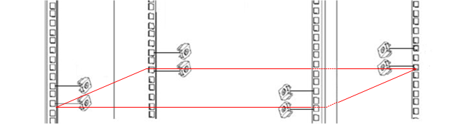
Install eight cage nuts (D) in the desired 1U slots of the rack.
Notes:
-
The red frame on the image denotes the Maestro Orchestrator inside the rack.
-
Install four cage nuts on each side of the Maestro Orchestrator.
-
Each rack 1U (unit) consists of three holes.
Install the cage nuts vertically, so that its ears engage the top and bottom holes only.
Example:

Step 4: Attaching the Rack Mount Blades to the Rack
While your installation partner is supporting the Maestro Orchestrator, perform these steps:
|
Step |
Instructions |
|---|---|
|
1 |
Attach the rack mount blades (B) to the back side (FRU side) of the rack at the level of the designated cage nuts. |
|
2 |
Insert four Phillips pan-head screws (E) in the designated cage nuts. |
|
3 |
Do not tighten the screws yet. |
Example:

Step 5: Sliding the Blades in the Rails
While your installation partner is supporting the Maestro Orchestrator, perform these steps:
|
Step |
Instructions |
|---|---|
|
1 |
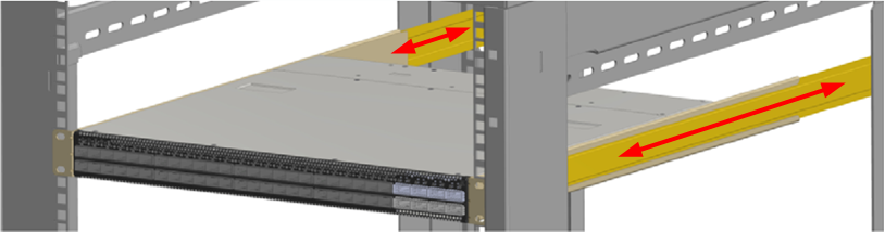
Slide each rack mount rails (A) into the corresponding rack mount blade (B). Note - Make sure the rack mount rail ears (C) face the rack's posts correctly. |
|
2 |
Slide the rack mount rails (A) inside the rack mount blades (B) to fit your rack's depth. |
|
3 |
Attach the rack mount rail ears (C) to the rack's posts. |
|
4 |
Use the four Phillips pan head screws (E) to secure each rack mount rail ear (C) to each side of the rack. |
|
5 |
Do not tighten the screws yet. |
Example:
Step 6: Tightening the Screws
While your installation partner is supporting the Maestro Orchestrator, tighten the eight Phillips pan-head screws (E) you inserted in the previous steps.
To tighten the screws, use a torque of 4.5±0.5 Nm.
Step 7: Cable Installation
It is possible to insert or remove all network cables while the Maestro Orchestrator is powered on.
To insert a cable, press the connector into the port receptacle until the connector is firmly seated. The LED indicator, corresponding to each data port, light up when the physical connection is established. When a logical connection is made, the relevant port LED lights up.
To remove a cable, disengage the locks and slowly pull the connector away from the port receptacle. The LED indicator for that port turns off, when the cable is unplugged.
|
|
Note - For more information about Port LEDs, see Port LEDs. |

Do not force the cable into the cage with more than 40 Newtons (4 kilogram-force / 9.0 pound-force). Greater insertion force may damage the cable, or the cage.

Step 8: Initial Power On
The power cords should be standard 3-wire AC power cords including a safety ground and rated for 15A or higher.
Check all boards, power supplies, and fan tray modules for proper insertion before plugging in a power cable.
The Maestro Orchestrator powers on automatically, when an AC power is applied.
|
Step |
Instructions |
|---|---|
|
1 |
Plug in the first power cable to the first PSU. |
|
2 |
Plug in the second power cable to the second PSU. |
|
3 |
Wait for the System Status LED to turn green (see System Status LED). It can take up to five minutes to power on the Maestro Orchestrator. If after five minutes the System Status LED is lit in red color, unplug the power cords and contact Check Point Support. |
|
4 |
Check the status of the Maestro Orchestrator LEDs (see LED Notifications). All of the LEDs must show status lights that are consistent with normal operation (initially flashes, and then lights in a steady color). Example:
|

|
|
Important:
|