LEDs
LED Notifications
The LEDs are an important tool for hardware event notification and troubleshooting.
|
Symbol |
LED Name |
Instructions |
Normal Condition |
|---|---|---|---|
|
|
Shows the health of the Quantum Maestro Orchestrator |
Steady green or flashing green during boot. |
|
|
|
Shows the health of the Fan Units. |
Steady green. |
|
|
|
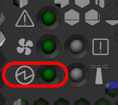
Shows the health of the Power Supply Units. |
Steady green. |
|
|
|
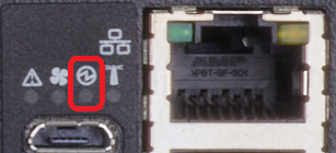
Lights up when the Quantum Maestro Orchestrator Exists only in MHO-170 and MHO-140. |
Off. |
|
|
|
Unit Identifier |
Not supported by Check Point Gaia OS. |
Off. |
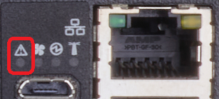
System Status LED
*Note - On MHO-140, this LED is located on the front panel and the rear panel.
|
LED Behavior |
Instructions |
Action Required |
|---|---|---|
|
Steady green |
The Orchestrator is up and running normally. |
None. |
|
Flashing green |
The Orchestrator is booting up. |
Wait for up to five minutes for the end of the booting process. |
|
Steady red |
Major error occurred. For example, the Orchestrator overheated, has a corrupted firmware, there is a CPU error. |
Check environmental conditions (room temperature). It may take up to five minutes to power on the Orchestrator. If the System Status LED is lit steady red for five minutes after you started the Orchestrator, unplug the Orchestrator and contact Check Point Support. |
|
Flashing for more than five minutes |
Software did not boot properly, and only firmware is running. |
Connect to the Orchestrator through the console port and check the software status. |
|
|
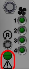
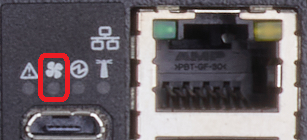
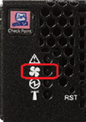
Important - FAN LEDs are always off. |
|
LED Behavior |
Instructions |
Action Required |
|---|---|---|
|
Steady green |
All fans are up and running normally. |
None. |
|
Steady red or amber |
Error. One or more fan units are not operating properly. |
Replace the faulty fan units. |
|
Off |
The Orchestrator boots. |
None. |
|
|
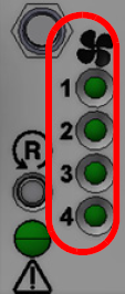
Important - FAN LEDs are always off. |
|
LED Behavior |
Instructions |
Action Required |
|---|---|---|
|
Steady green |
A specific fan unit is operating. |
None. |
|
Steady red or amber |
A specific fan unit is missing, or not operating properly. |
Replace the faulty fan unit. |
|
Off |
The Orchestrator boots. |
None. |
|
|
Important - With the fan unit removed, power pins are accessible within the module cavity. Do not insert tools or body parts into the fan unit cavity. |
Power Supply Unit Status LEDs
Power Supply Units LED shows the health of the Power Supply Units.
The Power Supply Units LED on the front panel shows the health of the Power Supply Units.
To provide power redundancy, there are two power supply inlets in Quantum Maestro Orchestrators.
A Quantum Maestro Orchestrator can operate with only one PSU connected.
In case the PSU is faulty, it is possible to add a second PSU to support hot-swap ability.
Each PSU has a single two-color LED on the right side of the PSU that indicates the status of the PSU.
The primary PSU is located on the left side, and the secondary PSU is located on the right side of the Quantum Maestro Orchestrator.
The PSU Status LEDs are located on the PSUs themselves.
Each PSU has one LED of its own.
|
LED Behavior |
Instructions |
Action Required |
|---|---|---|
|
Steady green |
All units are connected and running normally. |
None. |
|
Steady red or amber |
A PSU is faulty or disconnected. |
Make sure the AC cable is plugged in to the PSU. Make sure there is the AC power. If the problem persists, replace the faulty PSU. |
|
Off |
N / A |
None. |
|
LED Behavior |
Instructions |
Action Required |
|---|---|---|
|
Steady green |
The PSU is connected and running normally. |
None. |
|
Flashing green at 1Hz |
AC is present, only 12VSB on (PSU off), or PSU in Smart-On state. |
Contact Check Point Support. |
|
Steady read or amber |
AC cord is unplugged, or AC power is lost, while the second PSU still has AC input power. |
Plug in the AC cord to the faulty PSU. Make sure there is the AC power. |
|
|
PSU failure - voltage, current, temperature, or fan. |
Check the voltage of your AC power. If voltage is OK, contact Check Point Support. |
|
Flashing read or amber at 1Hz |
PSU warning events, where the PSU continues to operate; high temperature, high power, high current, slow fan. |
Contact Check Point Support. |
|
Off |
No input AC power at all PSUs. |
Make sure there is the AC power. Plug in the AC cords. If the AC power is OK, contact Check Point Support. |
Port LEDs
Port LEDs on are located on the front panel.
In MHO-175, all port LEDs are located on the right side.
There are 32 LEDs that correspond to the 32 physical ports.
You can connect 1-to-4 breakout cables![]() An optical fiber cable that contains several jacketed simplex optical fibers that are packaged together inside an outer jacket. Synonyms: Fanout cable, Fan-Out cable, Splitter cable. to physical ports and get a maximum of 128 logical ports.
An optical fiber cable that contains several jacketed simplex optical fibers that are packaged together inside an outer jacket. Synonyms: Fanout cable, Fan-Out cable, Splitter cable. to physical ports and get a maximum of 128 logical ports.
After you connect a breakout cable to a physical port, you get four additional interfaces starting from the original interface name. You assign these interfaces to Security Groups![]() A logical group of Security Appliances that provides Active/Active cluster functionality. A Security Group can contain one or more Security Appliances. Security Groups work separately and independently from each other. To the production networks, a Security Group appears a single Security Gateway. Every Security Group contains: (A) Applicable Uplink ports, to which your production networks are connected; (B) Security Appliances (the Quantum Maestro Orchestrator determines the applicable Downlink ports automatically); (C) Applicable management port, to which the Check Point Management Server is connected..
A logical group of Security Appliances that provides Active/Active cluster functionality. A Security Group can contain one or more Security Appliances. Security Groups work separately and independently from each other. To the production networks, a Security Group appears a single Security Gateway. Every Security Group contains: (A) Applicable Uplink ports, to which your production networks are connected; (B) Security Appliances (the Quantum Maestro Orchestrator determines the applicable Downlink ports automatically); (C) Applicable management port, to which the Check Point Management Server is connected..
Example - When you connect a breakout cable to the top port 8 (interface "eth1-29"), you get:
|
Port |
Interface |
Port |
|---|---|---|
|
8 |
eth1-29 |
Port 1/8/1 |
|
eth1-30 |
Port 1/8/2 |
|
|
eth1-31 |
Port 1/8/3 |
|
|
eth1-32 |
Port 1/8/4 |
|
|
Note - For more information about the ports and interface names in Gaia, see Quantum Maestro Orchestrator Ports and Gaia OS Interfaces. |
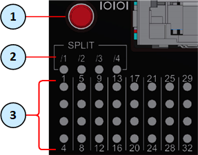
To see the state of split ports, it is necessary to use the control button to select the LED indication mode.
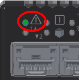
The control button (item 1) selects one of the five available LED indication modes in a cycle.
The four LEDs in the section SPLIT /1 /2 /3 /4 (item 2) show the current LED indication mode.
The port LEDs (item 3) show the port state - link (up or down) and traffic (flowing or not).
Port LED Behavior in the LED Indication Mode 0:
|
LED Behavior |
Port State |
Action Required |
|---|---|---|
|
Off |
Link is down. |
None. |
|
Steady green |
|
None. |
|
Flashing green |
|
None. |
|
Flashing amber |
Undetermined state. |
Select another LED Indication Mode - 1, 2, 3, or 4. |
Port LED Behavior in the LED Indication Modes 1, 2, 3, or 4:
|
LED Behavior |
Port State |
Action Required |
|---|---|---|
|
Off |
Link is down. |
Check the cable. |
|
Steady green |
Link is up in the corresponding split port, but the traffic is not flowing in that split port. |
None. |
|
Flashing green |
Link is up in the corresponding split port, and the traffic is flowing in that split port. |
None. |
|
Flashing amber |
A problem with the link in the corresponding split port. |
Check the cable, and replace if needed. |
In MHO-170, the status of each pair of adjacent ports is indicated by two LEDs:
Example:

Port LED Behavior:
|
LED Behavior |
Port State |
Action Required |
|---|---|---|
|
Off |
Link is down. |
Check the cable. |
|
Steady green |
Link is up, but there is no traffic. |
None. |
|
Flashing green |
Link is up, and the traffic is flowing. |
None. |
|
Flashing amber |
A problem with the link. |
Check the cable, and replace if needed. |
In MHO-140, the status of each pair of adjacent ports 1 to 48 is indicated by two LEDs.
Example:

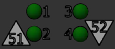
In MHO-140, the status of each pair of adjacent QSFP28 ports 49 to 56 is indicated by four LEDs:
-
While the bottom LEDs signify the port status in regular condition, the upper LEDs operate only when the port is split with a breakout cable.
-
When the upper port is split to four interfaces, its bottom port is disabled.
-
If the ports run at a 100 GbE or 40 GbE speed each, the two lower LEDs (2 and 4) light in green.
Port LED Behavior:
|
LED Behavior |
Port State |
Action Required |
|---|---|---|
|
Off |
Link is down. |
Check the cable. |
|
Steady green |
Link is up, but there is no traffic. |
None. |
|
Flashing green |
Link is up, and the traffic is flowing. |
None. |
|
Flashing amber |
A problem with the link. |
Check the cable, and replace if needed. |


