Connecting Two Quantum Maestro Orchestrators for Redundancy
This section describes the connection of two Quantum Maestro Orchestrators![]() A scalable Network Security System that connects multiple Check Point Security Appliances into a unified system. Synonyms: Orchestrator, Quantum Maestro Orchestrator, Maestro Hyperscale Orchestrator. Acronym: MHO. for Redundancy on the same site.
A scalable Network Security System that connects multiple Check Point Security Appliances into a unified system. Synonyms: Orchestrator, Quantum Maestro Orchestrator, Maestro Hyperscale Orchestrator. Acronym: MHO. for Redundancy on the same site.
|
|
Best Practice - For redundancy, install and connect two Quantum Maestro Orchestrators |

|
|
Warning - It is critical to protect the Maestro Sites against both malicious and unintentional threats:
|

|
|
Important - To prevent traffic outage in an environment with two Orchestrators on a Single Site, make sure each Uplink interface and each Management interface are configured as a Bond interface. Example:
|

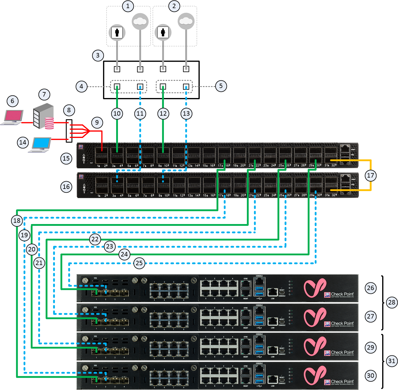
Diagram
|
|
Important - It is possible to connect only two Quantum Maestro Orchestrators of the same model (see MBS-5038). |
|
|
Best Practice - Connect cables to the same Uplink and Downlink ports |
Notes:
-
This logical diagram is based on MHO-170, but applies equally to all Quantum Maestro Orchestrator models.
-
This logical diagram shows two example Security Groups
 A logical group of Security Appliances that provides Active/Active cluster functionality. A Security Group can contain one or more Security Appliances. Security Groups work separately and independently from each other. To the production networks, a Security Group appears a single Security Gateway. Every Security Group contains: (A) Applicable Uplink ports, to which your production networks are connected; (B) Security Appliances (the Quantum Maestro Orchestrator determines the applicable Downlink ports automatically); (C) Applicable management port, to which the Check Point Management Server is connected. that contain two Security Appliances and two Uplink ports Interfaces on the Quantum Maestro Orchestrator used to connect to external and internal networks. Gaia operating system shows these interfaces in Gaia Portal and in Gaia Clish. SmartConsole shows these interfaces in the corresponding SMO Security Gateway object. each.
Example for MHO-170:
|
Item |
Description |
||
|---|---|---|---|
|
1 |
Network 1 connected to ports on the Networking Device (3). |
||
|
2 |
Network 2 connected to ports on the Networking Device (3). |
||
|
3 |
Networking Device (router or switch) that connects your Network 1 and Network 2 to the Quantum Maestro Orchestrators (15 and 16) with Bond interfaces (Link Aggregation). |
||
|
4 |
Bond interface that connects Network 1 to the Quantum Maestro Orchestrators (15 and 16). This Bond interface provides a redundant Uplink connection for the traffic inspected by the Security Appliances (29 and 30) in the applicable Security Group (31). |
||
|
5 |
Bond interface that connects Network 2 to the Quantum Maestro Orchestrators (15 and 16). This Bond interface provides a redundant Uplink connection for the traffic inspected by the Security Appliances (26 and 27) in the applicable Security Group (28). |
||
|
6 |
SmartConsole Client that connects to the Management Server (7). |
||
|
7 |
Management Server that manages Security Groups configured on the Quantum Maestro Orchestrators (15 and 16). |
||
|
8 |
Layer 2 switch. |
||
|
9 |
A Breakout cable
|
||
|
10 |
A DAC cable |
||
|
11 |
A DAC cable, Fiber cable (with transceivers), or Breakout cable that connects a second slave of the first Bond (4) on the Networking Device (3) to the second Quantum Maestro Orchestrator (16). |
||
|
12 |
A DAC cable, Fiber cable (with transceivers), or Breakout cable that connects a first slave of the second Bond (5) on the Networking Device (3) to the first Quantum Maestro Orchestrator (15). |
||
|
13 |
A DAC cable, Fiber cable (with transceivers), or Breakout cable that connects a second slave of the second Bond (5) on the Networking Device (3) to the second Quantum Maestro Orchestrator (16). |
||
|
14 |
Client you can use to configure the Gaia Operating System on the Security Appliances in Security Groups. You connect:
|
||
|
15 |
First Quantum Maestro Orchestrator:
|
||
|
16 |
Second Quantum Maestro Orchestrator:
|
||
|
17 |
A DAC that connects the dedicated Synchronization ports on the Quantum Maestro Orchestrators (15 and 16).
|
||
|
18 |
A DAC cable, Fiber cable (with transceivers), or Breakout cable that connects a Downlink port on the first Quantum Maestro Orchestrator (15) to the Security Appliance (30). |
||
|
19 |
A DAC cable, Fiber cable (with transceivers), or Breakout cable that connects a Downlink port on the second Quantum Maestro Orchestrator (16) to the Security Appliance (30). |
||
|
20 |
A DAC cable, Fiber cable (with transceivers), or Breakout cable that connects a Downlink port on the first Quantum Maestro Orchestrator (15) to the Security Appliance (29). |
||
|
21 |
A DAC cable, Fiber cable (with transceivers), or Breakout cable that connects a Downlink port on the second Quantum Maestro Orchestrator (16) to the Security Appliance (29). |
||
|
22 |
A DAC cable, Fiber cable (with transceivers), or Breakout cable that connects a Downlink port on the first Quantum Maestro Orchestrator (15) to the Security Appliance (27). |
||
|
23 |
A DAC cable, Fiber cable (with transceivers), or Breakout cable that connects a Downlink port on the second Quantum Maestro Orchestrator (16) to the Security Appliance (27). |
||
|
24 |
A DAC cable, Fiber cable (with transceivers), or Breakout cable that connects a Downlink port on the first Quantum Maestro Orchestrator (15) to the Security Appliance (26). |
||
|
25 |
A DAC cable, Fiber cable (with transceivers), or Breakout cable that connects a Downlink port on the second Quantum Maestro Orchestrator (16) to the Security Appliance (26). |
||
|
26 |
Security Appliance 2 in the Security Group 2 (28). |
||
|
27 |
Security Appliance 1 in the Security Group 2 (28). |
||
|
28 |
All Security Appliances assigned to the Security Group 2. |
||
|
29 |
Security Appliance 2 in the Security Group 1 (31). |
||
|
30 |
Security Appliance 1 in the Security Group 1 (31). |
||
|
31 |
All Security Appliances assigned to the Security Group 1. |

|
|
Notes:
|
|
|
Important:
|
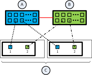
Connecting cables between Downlink ports on each Quantum Maestro Orchestrator and 2 ports on the Dual Port Card on each Security Appliance
|
Illustration |
Instructions |
|---|---|
|
|
On each Security Appliance (C) in the Security Group:
|
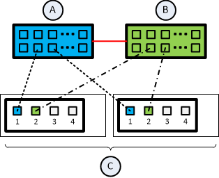
Connecting cables between Downlink ports on each Quantum Maestro Orchestrator and 1 out of 4 ports on the Quad Port Card on each Security Appliance
|
Illustration |
Instructions |
|---|---|
|
|
On each Security Appliance (C) in the Security Group:
|
Connecting cables between Downlink ports on each Quantum Maestro Orchestrator and 2 out of 4 ports on the Quad Port Card on each Security Appliance
|
Illustration |
Instructions |
||
|---|---|---|---|
|
|
On each Security Appliance (C) in the Security Group:
|
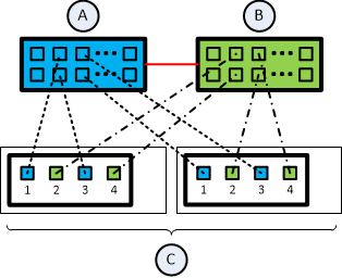
Legend
|
Item |
Description |
|---|---|
|
A |
First Orchestrator. |
|
B |
Second Orchestrator. |
|
C |
Security Appliances in Security Groups. |
|
|
A DAC cable connected to the dedicated Synchronization ports on the Orchestrators. |
|
|
Cables that connect odd ports on the Quad Port Card to the first Orchestrator. |
|
|
Cables that connect even ports on the Quad Port Card to the second Orchestrator. |


|
|
Best Practice for Security Appliances 23000 series: Install the expansion cards in this order:
Use Slots 1 and 2 only after all other slots are populated. Overview of the expansion slots on the front panel:
|
Workflow
|
Step |
Device |
Instructions |
|---|---|---|
|
1 |
On the Networking Device (3) |
Perform these steps (refer to the device vendor documentation):
|
|
2 |
On the first Quantum Maestro Orchestrator (15) |
Perform these steps:
See these sections: |
|
3 |
On the second Quantum Maestro Orchestrator (16) |
Perform these steps:
See these sections: |
|
4 |
On both Quantum Maestro Orchestrators (15 and 16) |
Connect a DAC cable (17) between the dedicated synchronization port (in our example, Port 32) on the first Quantum Maestro Orchestrator (15) and the dedicated synchronization port (in our example, Port 32) on the second Quantum Maestro Orchestrator (16). |
|
5 |
On the first Quantum Maestro Orchestrator (15) |
With cable (9), connect the Management Server to the Management port (in our example, Port 1). In our example, we used a Breakout cable because we have two Security Groups. For more information that applies to MHO-175, see: For more information that applies to MHO-170, see: For more information that applies to MHO-140, see: |
|
6 |
One of the two Quantum Maestro Orchestrators (15 or 16) |
Perform these steps:
|
 on the rear panel.