Hardware Components
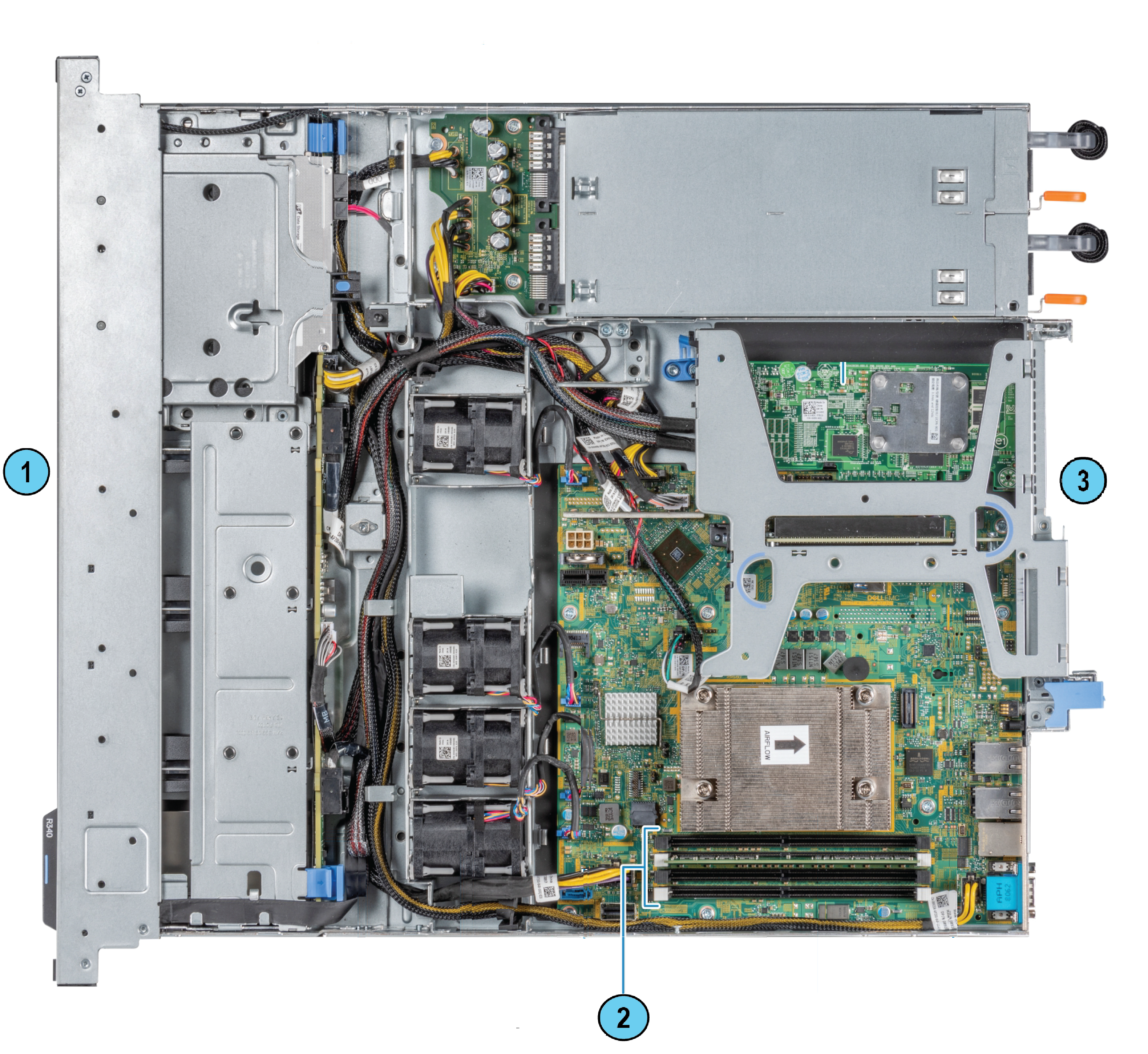
|
Item |
Description |
|---|---|
|
1 |
Front panel |
|
2 |
4 memory module sockets (located under the cooling air shroud) |
|
3 |
Rear panel |
About Memory DIMM Sockets
The memory sockets have black and white colored ejectors. In the appliance configuration diagram, note that:
-
The view shown is always from the top.
-
The front panel of the appliance is always at the bottom of the diagram.
| Item | Description |
|---|---|
|
|
Memory sockets with DIMMs installed |

Smart-1 625 DIMM Configuration
The Smart-1 625 Security Management Appliance has a default memory configuration of 32GB: 4x8GB, with four DIMMs.
|
To upgrade to |
Use DIMMs |
Procedure |
Sockets |
|---|---|---|---|
|
64GB |
4x16GB |
Remove the four 8GB DIMMs and install four 16GB DIMMs in the same sockets |
A1-A4 |
The memory socket numbers, shown in the configuration diagram, are marked on the cooling shroud and align with the respective memory sockets.
Default and upgraded configuration:
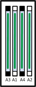
Top view (front of the Smart-1 625 is at the bottom of the diagram)
Procedure
Memory Kit Contents
-
Installation guide - Smart-1 Installing and Removing Memory
-
Expansion DIMMs
-
Electrostatic Discharge (ESD) grounding wrist strap (anti-static)
To install a new DIMM:
-
Prepare the appliance.
-
Remove the cooling air shroud.
-
Remove a DIMM.
-
Install a DIMM.
-
Install the cooling air shroud.
-
Reassemble the appliance.
- Verify the memory configuration.
Preparing the Appliance
-
Make sure to follow the safety instructions.
- Shut down the appliance:
In Gaia Portal:
Go to Maintenance > Shut Down, and click Halt.
In Gaia Clish:
Run: halt
-
Open the retention strap that secures the power cables to the PSUs.
-
Disconnect the power cables from the AC PSUs.
-
Remove the hook-and-loop straps that hold and secure the system cables, if they interfere with the PSU removal.
-
Remove the appliance from the rack.
-
Put the Electrostatic Discharge (ESD) grounding strap on your wrist and attach the other end to a grounding point.
-
Remove the appliance cover.
-
Use a 1/4 inch flat head or a Phillips #2 screwdriver to turn the lock counter clockwise to the unlocked position (1).
-
Open the release latch until the system cover slides back (2).
-
Lift the cover from the system (3).
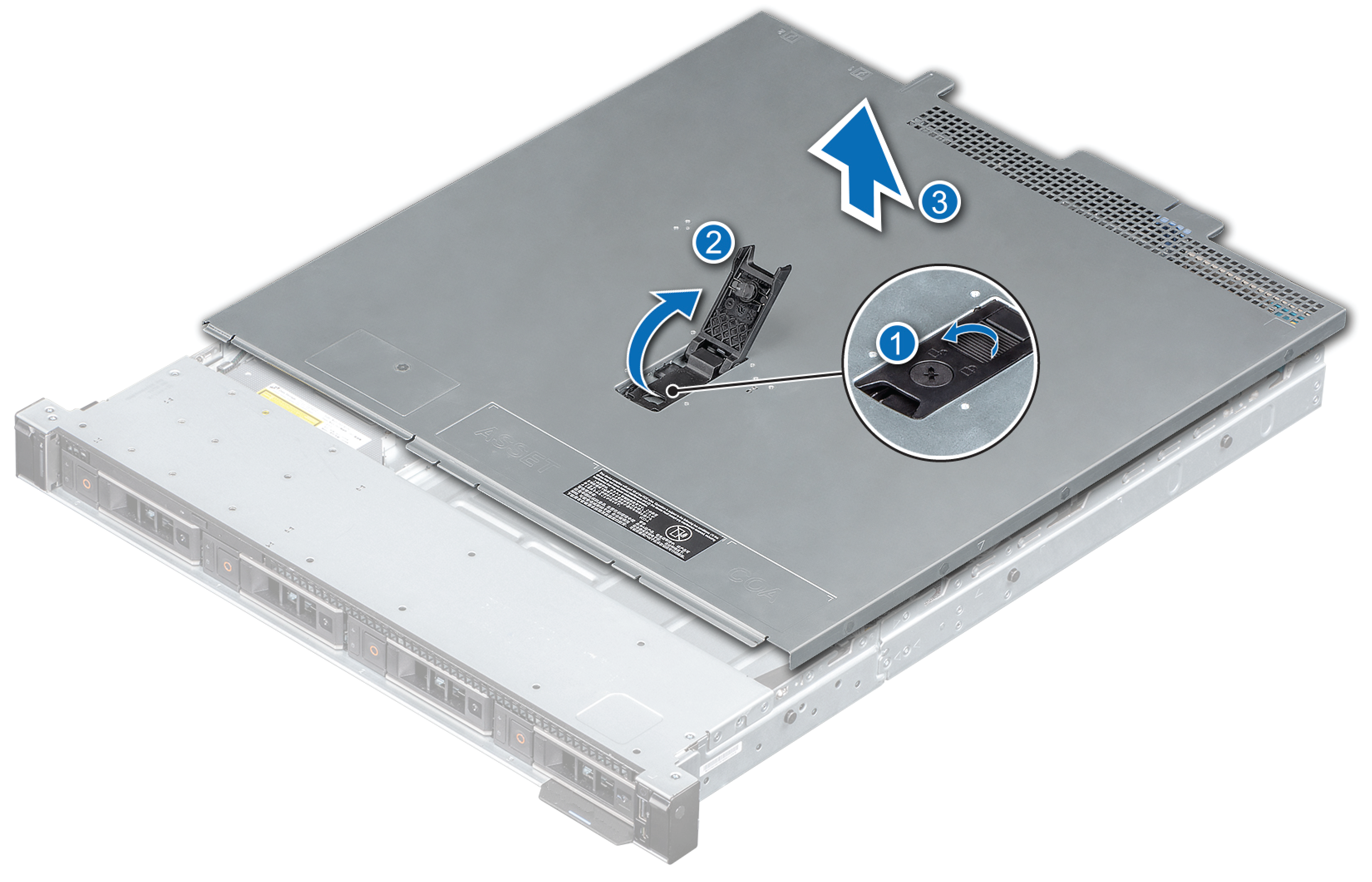
-
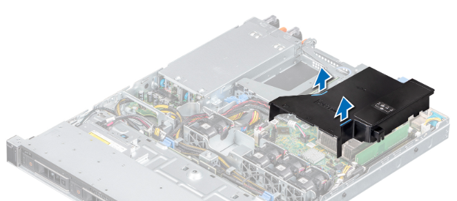
Removing the Cooling Air Shroud
To remove the air shroud:
-
Locate the blue touch points.
-
Lift the air shroud out of the appliance.
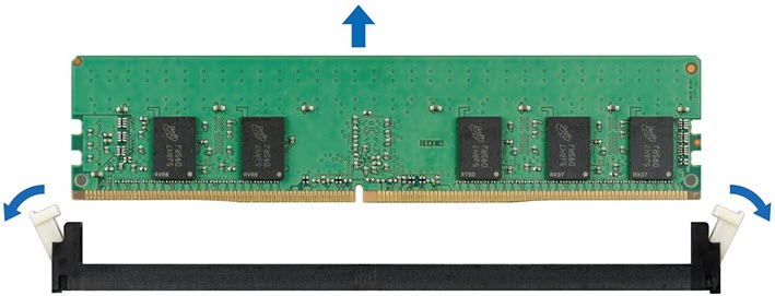
Removing a DIMM

|
Warning - Allow the DIMMs to cool after you power off the system. Handle the memory DIMMs by the card edges and avoid touching the components or metallic contacts on the DIMM. |
To remove a DIMM:
-
Locate the appropriate memory socket.
Caution - Handle each DIMM only by the card edges, ensuring not to touch the middle of the DIMM or metallic contacts.
-
Push the ejectors outward on both ends of the memory socket to release from the socket.
-
Lift and remove the DIMM from the system.
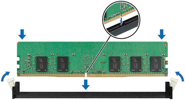
Installing a DIMM
To install a DIMM:
-
Locate the appropriate memory socket.
Caution - Handle each DIMM only by the card edges, ensuring not to touch the middle of the DIMM or metallic contacts.
Caution - To prevent damage to the DIMM or the memory socket during installation, do not bend or flex the DIMM. You must insert both ends of the DIMM simultaneously.
-
Open the ejectors on the memory socket outward to allow the DIMM to be inserted into the socket.
-
Align the edge connector of the DIMM with the alignment key of the memory socket, and insert the DIMM in the socket.
Caution - Do not apply pressure at the center of the DIMM; apply pressure at both ends of the DIMM evenly.
Note - The memory socket has an alignment key that enables you to install the DIMM in the socket in only one orientation.
-
Press the DIMM with your thumbs until the socket levers firmly click into place.
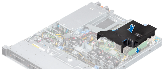
Installing the Cooling Air Shroud
To install the air shroud:
-
Install the slot on the air shroud with the standoff on the chassis.
-
Lower the air shroud into the appliance until it is firmly seated.
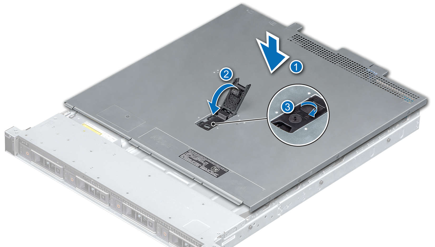
Reassembling the Appliance
Make sure that all internal cables are routed correctly and connected, and no tools or extra parts are left inside the appliance.
To reassemble the appliance:
-
Align the tabs on the cover with the guide slots on the appliance (1).
-
Close the system cover release latch (2).
-
Using a 1/4 inch flat head or Phillips #2 screwdriver, turn the lock clockwise to the lock position (3).
-
Install the appliances into the rack. See the Smart-1 625 Installing the Telescopic Rails Guide.
-
Connect the power cables from the AC PSUs.
-
If you opened the hook-and-loop straps, close them to secure the appliance cables.
-
Press the Power button on the front panel to turn on the Security Management appliance.
Verifying the Memory Configuration
To make sure that the memory configuration is correct:
-
Connect to the command line.
-
Log in to the Expert mode.
-
Run:
free -gExample output from Smart-1 625 with 32GB of memory:

The amount of installed memory is shown in the row named
Memunder the column namedtotal.