Configuring Virtual System Load Sharing (VSLS)
|
|
Important - This section does not apply to Scalable Platforms (Maestro and Chassis). On Scalable Platforms, use the Gaia gClish command " See the:
|

Introduction
VSX Clusters can efficiently balance network traffic load by distributing active Virtual Systems between VSX Cluster Members.
This capability is known as Virtual System Load Sharing (VSLS).
Virtual System Load Sharing is a cluster technology that assigns traffic for Virtual Systems to different Active VSX Cluster Members, which has these benefits:
-
Capacity: VSLS leverages the cluster machines to handle greater network volume by efficiently dividing the load.
-
Redundancy: VSLS gives full redundancy by maintaining connectivity for all Virtual Systems even when individual VSX Cluster Members fail.
-
Scalability: VSLS provides linear scalability for throughput and session rate.
-
Cost Effectiveness: A VSLS cluster uses standard network switches to get cost effective Load Sharing.
-
Ease of Configuration: Virtual Systems are automatically distributed between all the VSX Cluster Members - no special configuration is required.
-
Priority Designation: Mission-critical Virtual Systems can be separated from the other Virtual Systems to utilize better bandwidth and resources.
-
System Scalability: Every VSX Cluster Member added to the cluster increases the overall system capacity and redundancy.
|
|
Important - These Virtual Devices are not supported when the Per-Virtual System state is enabled:
|
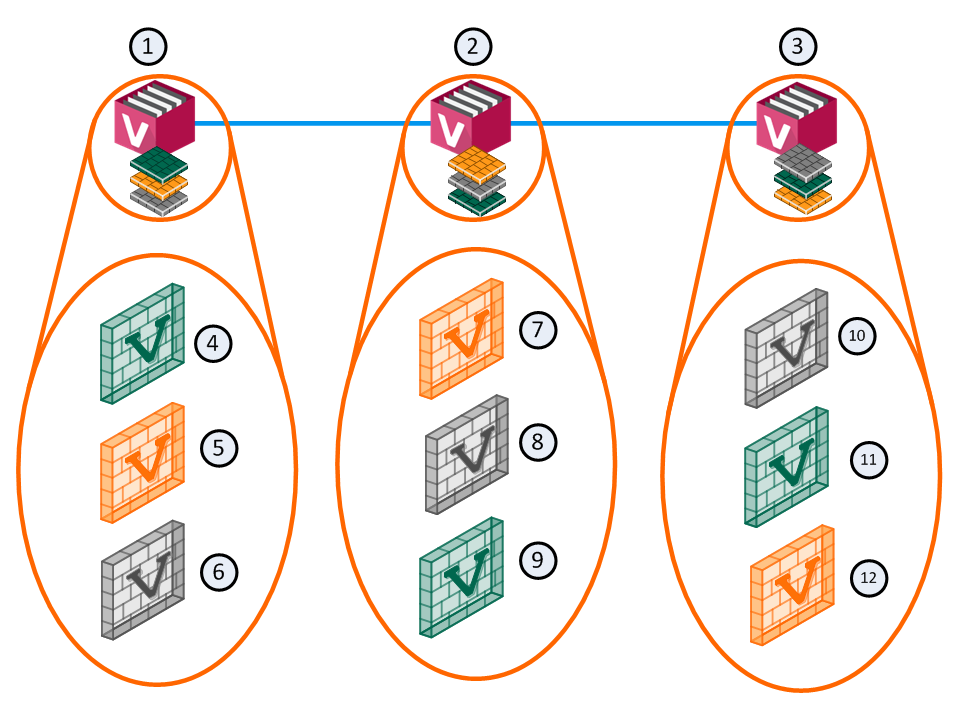
In an example deployment scenario with three VSX Cluster Members, each with three Virtual Systems: an equalized Load Sharing deployment might have one Active Virtual System on each VSX Cluster Member.
|
Item |
Description |
|
Item |
Description |
|---|---|---|---|---|
|
1 |
VSX Cluster Member 1 |
|
8 |
Virtual System 2 is Backup |
|
2 |
VSX Cluster Member 2 |
|
9 |
Virtual System 3 is Active |
|
3 |
VSX Cluster Member 3 |
|
10 |
Virtual System 1 is Backup |
|
4 |
Virtual System 1 is Active |
|
11 |
Virtual System 2 is Active |
|
5 |
Virtual System 2 is Standby |
|
12 |
Virtual System 3 is Standby |
|
6 |
Virtual System 3 is Backup |
|
|
Sync Network |
|
7 |
Virtual System 1 is Standby |
|
|
|

A different member hosts the active peer for each Virtual System. This distribution spreads the load equally between the VSX Cluster Members.
When you create a Virtual System, VSX automatically assigns Standby and Backup states to the applicable peers and distributes them between the other VSX Cluster Members.
In the event that a VSX Cluster Member fails, VSLS directs traffic destined to affected Virtual Systems to their fully synchronized Standby peers, which then become Active. At the same time, a Backup Virtual System switches to Standby, and synchronizes with the newly Active Virtual System.
In the event that an individual active Virtual System fails, it immediately fails over to its Standby peer and one of its Backup peers becomes the Standby, synchronizing with the newly Active peer.
VSLS lets administrators manually assign Virtual Systems to specified VSX Cluster Members, or lets VSX automatically assign Virtual System traffic dynamically.
Requirements
All Virtual Systems in all VSX Cluster Members must have direct connectivity with each other.
Connectivity must be accomplished using switches or VLAN connections.
This is required for detecting and assigning Virtual System states.
Virtual System Priority
Virtual System priority refers to a preference regarding which VSX Cluster Member hosts a Virtual System's Active, Standby, and Backup states.
This preference is expressed as an integer value.
|
Priority |
Definition |
|---|---|
|
0 |
Highest priority, indicating the cluster designated to host the Virtual System Active state. |
|
1 |
Second highest priority, indicating the member designated to host the Virtual System Standby state. |
|
> 1 |
Lower priorities, indicating the VSX Cluster Members designated to host a Virtual System Backup state. The VSX Cluster Member assigned priority 2 is the first to switch the Virtual System to the Standby state in the event of a failure of either the Active or Standby Virtual System. A VSX Cluster Member assigned priority 3 is the next in line to come online in the event of another failure. |
You can change the priority designation with the "vsx_util vsls" command on the Management Server.
Virtual System Weight
Because not all Virtual Systems are equal in terms of traffic and load, VSLS allows you to assign "weights" to individual Virtual Systems.
The weight of a Virtual System affects the dispersal pattern of other Virtual Systems across VSX Cluster Members.
When you assign a heavier weight to a Virtual System gives it a larger share of resources on a specific VSX Cluster Member, and disperses the other Virtual Systems to other VSX Cluster Members.
By default, all Virtual Systems are assigned an equal weight factor of 10.
You can change the weight factor with the "vsx_util vsls" command on the Management Server.
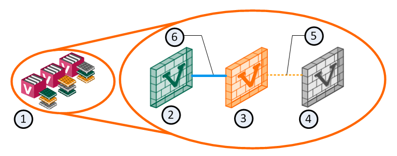
Virtual System States
VSLS adds a Backup state to the existing Active and Standby states.
The Backup state contains the latest configuration settings for each Virtual System, but does not receive state table synchronization.
The figure below illustrates the relationship between Virtual System states.
|
Item |
Description |
|---|---|
|
1 |
VSX Cluster with 3 Cluster Members, each running 3 Virtual Systems (2, 3, and 4) |
|
2 |
Virtual System 1 on VSX Cluster Member 1 is Active |
|
3 |
Virtual System 1 on VSX Cluster Member 2 is Standby |
|
4 |
Virtual System 1 on VSX Cluster Member 3 is Backup |
|
5 |
Policy updates only |
|
6 |
State tables are synchronized |
Each Virtual System peer in a VSLS cluster is replicated on all VSX Cluster Members, and each copy exists in a different state.
The Active and Standby states are synchronized, so that the Standby peer can immediately become Active in the event of a failure of the Active Virtual System or VSX Cluster Member.
When this happens, the Backup peer becomes the Standby, and immediately synchronizes with the new Active Virtual System.
VSLS reduces the load on the synchronization network by not synchronizing the Backup Virtual System state tables with the Active Virtual System until a failover occurs.
Normalized VSLS Deployment Scenario
For example, you can have three VSX Cluster Members, each with three Virtual Systems.
In this configuration, an equalized Load Sharing deployment could have one Active Virtual System on each VSX Cluster Member.

|
Item |
Description |
|
Item |
Description |
|---|---|---|---|---|
|
1 |
VSX Cluster Member 1 |
|
8 |
Virtual System 2 is Backup |
|
2 |
VSX Cluster Member 2 |
|
9 |
Virtual System 3 is Active |
|
3 |
VSX Cluster Member 3 |
|
10 |
Virtual System 1 is Backup |
|
4 |
Virtual System 1 is Active |
|
11 |
Virtual System 2 is Active |
|
5 |
Virtual System 2 is Standby |
|
12 |
Virtual System 3 is Standby |
|
6 |
Virtual System 3 is Backup |
|
|
Sync Network |
|
7 |
Virtual System 1 is Standby |
|
|
|
A different VSX Cluster Member can host the Active state of each Virtual System.
This distribution of Virtual Systems spreads the load between the VSX Cluster Members.
When a Virtual System is created, the system automatically creates Standby and Backup states and distributes them between the other VSX Cluster Members.
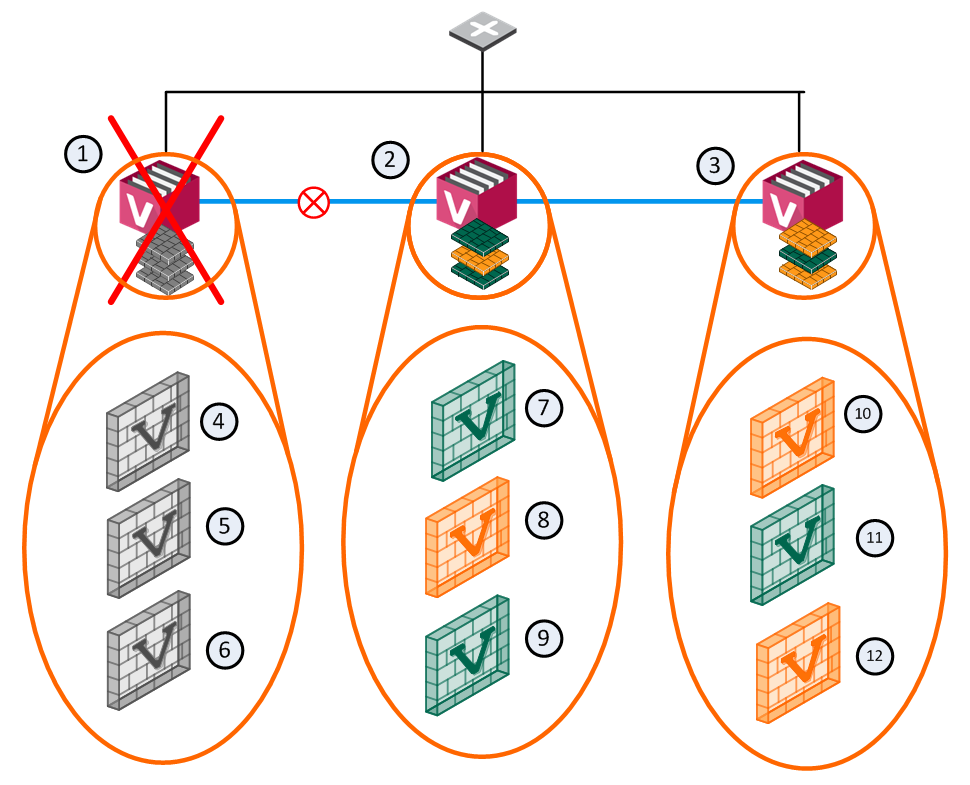
VSX Cluster Member Failure Scenario
In the event that a member fails or experiences a connectivity problem, VSLS detects the problem and routes traffic for the affected Virtual Systems to their corresponding Standby Virtual Systems.
Standby Virtual Systems, which are fully synchronized with their active peers, change immediately to the Active state and preserve active connections.
At the same time, the backup Virtual Systems switch to Standby, and synchronize fully with the newly active Virtual Systems.
|
Item |
Description |
|
Item |
Description |
|---|---|---|---|---|
|
1 |
VSX Cluster Member 1 |
|
8 |
Virtual System 2 is Standby |
|
2 |
VSX Cluster Member 2 |
|
9 |
Virtual System 3 is Active |
|
3 |
VSX Cluster Member 3 |
|
10 |
Virtual System 1 is Standby |
|
4 |
Virtual System 1 is Down |
|
11 |
Virtual System 2 is Active |
|
5 |
Virtual System 2 is Down |
|
12 |
Virtual System 3 is Standby |
|
6 |
Virtual System 3 is Down |
|
|
Sync Network |
|
7 |
Virtual System 1 is Active |
|
|
Network Traffic |

In this scenario, VSX Cluster Member 1 fails and its Active and Standby Virtual Systems fail over to VSX Cluster Member 2 and VSX Cluster Member 3.
The Active Virtual System (VS1) moves to VSX Cluster Member 2 and directs all VS1 traffic itself.
Its Backup peer on VSX Cluster Member 3 synchronizes with the new Active Virtual System and becomes the Standby.
VS2 on VSX Cluster Member 2 becomes the Standby and synchronizes with the Active peer on VSX Cluster Member 3.
For VS3, the Active and Standby peers remain the same.
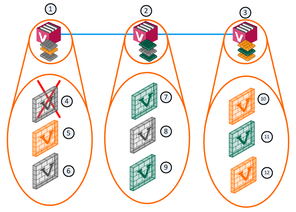
Virtual System Failure Scenario
In a failure scenario where an active Virtual System fails on one member, but the Standby and Backup Virtual Systems remain up: the Active Virtual System fails over to its Standby peer, and its Backup becomes the Standby.
The new Standby synchronizes with the new Active member.
|
Item |
Description |
|
Item |
Description |
|---|---|---|---|---|
|
1 |
Member 1 |
|
8 |
VS 2 Backup |
|
2 |
Member 2 |
|
9 |
VS 3 Active |
|
3 |
Member 3 |
|
10 |
VS 1 Standby |
|
4 |
VS 1 Down |
|
11 |
VS 2 Active |
|
5 |
VS 2 Standby |
|
12 |
VS 3 Standby |
|
6 |
VS 3 Backup |
|
|
Sync Network |
|
7 |
VS 1 Active |
|
|
|
All other Virtual Systems continue to function as usual, and no failover occurs.
Failure Recovery
When the failed VSX Cluster Member or Virtual System comes back online, the system returns to its original Load Sharing configuration.
Configuring a VSX Cluster in VSLS Mode
-
 Install the VSX Cluster Members
See the R82 Installation and Upgrade Guide - Chapter Installing a ClusterXL, VSX Cluster, VRRP Cluster - Section Installing a VSX Cluster.
-
Enable the Per Virtual System State mode on each VSX Cluster Member
The Per Virtual System State mode enables active Virtual Systems to be placed on different VSX Cluster Members, and for Virtual System-specific failover. This setting is mandatory for VSLS.
On each VSX Cluster Member:
-
Connect to the command line.
-
Log in to the Expert mode.
-
Run:
cpconfig -
Select:
Enable Check Point Per Virtual System State
-
When the question appears:
Would you like to enable Per Virtual System state?Enter y to confirm.
-
Reboot the VSX Cluster Member.
-
-
In SmartConsole, create a new VSLS VSX Cluster object
-
Connect with SmartConsole to the Security Management Server or Main Domain Management Server that manages the VSX Cluster.
-
From the navigation panel, click Gateways & Servers.
-
At the top, click Objects menu > More object types > Network Object > Gateways and Servers > VSX > New Cluster.
The VSX Cluster Wizard > General Properties opens.
-
Create and configure the new VSX Cluster.
See Working with VSX Clusters.
-
On the General Properties page, from VSX Cluster Platform, select ClusterXL Virtual System Load Sharing.
-
Complete the VSX Cluster Wizard.
-
-
-
Use the '
vsx_util vsls' command on the Management ServerUse the "
vsx_util vsls" command (see vsx_util vsls) on the Management Server to do different Virtual System Load Sharing configuration tasks:-
Show the current VSLS configuration
-
Distribute Virtual Systems equally between VSX Cluster Members
-
Set all Virtual Systems as Active on one VSX Cluster Member
-
Manually define the priority and weight for individual Virtual Systems
-
Toggle VSLS mode between Active Up and Primary Up
-
Import VSLS configuration from CSV text files
-
Export VSLS configuration to CSV text files
Procedure:
-
Connect to the command line on the Management Server.
-
Log in to the Expert mode.
-
Run:
vsx_util vsls -
Enter the IP address of the Security Management Server or Domain Management Server.
-
Enter the Management Server administrator user name and password.
-
Select the applicable option from the VSLS menu.
-
Viewing VSLS Status
To view the current VSLS status and Virtual System distribution between VSX Cluster Members, select Display current VS Load Sharing configuration from the VSLS menu.
Virtual System priority refers to a preference regarding which VSX Cluster Member hosts a Virtual System's Active, Standby, and Backup states.
This preference is expressed as an integer value.
|
Priority |
Definition |
|---|---|
|
0 |
Highest priority, indicating the VSX Cluster Member designated to host the Virtual SystemActive state. |
|
1 |
Second highest priority, indicating the VSX Cluster Member designated to host the Virtual SystemStandby state. |
|
> 1 |
Lower priorities, indicating VSX Cluster Members designated to host a Virtual System's Backup state. The VSX Cluster Member assigned priority 2 will be the first to switch the Virtual System to the Standby state in the event of a failure of either the Active or Standby Virtual System. A VSX Cluster Member assigned priority 3 would be the next in line to come online in the event of another failure. |
Each Virtual System is assigned a weight factor, which determine its traffic volume relative to the total traffic volume (the sum of all weight factors) on a given VSX Cluster Member.
VSX uses the weight factor to determine the most efficient distribution of Virtual Systems between VSX Cluster Members.
System resource allocation is not affected by the weight factor, and VSX does not take weight into consideration for any other purpose.
By default, all Virtual Systems are assigned an equal weight factor of 10.
Distributing Virtual Systems Between VSX Cluster Members
The primary advantage of VSLS is that it distributes Active, Standby and Backup Virtual Systems between VSX Cluster Members to maximize throughput and user response time.
You can distribute Virtual Systems in one of these ways:
This lets you automatically distribute Active Virtual Systems between VSX Cluster Members, so that all VSX Cluster Members are equally loaded, based on assigned weights and existing or default priority definitions.
-
From the VSLS menu (see vsx_util vsls), select the VSX Cluster object.
-
Select Distribute all Virtual Systems so that each cluster member is equally loaded.
-
At the "
Save & apply configuration?" prompt, enter y to continue.
The update process may take several minutes or longer to complete, depending on the number of Virtual Systems and VSX Cluster Members.
-
From the VSLS menu (see vsx_util vsls), select the VSX Cluster object.
-
Select Set all VSs active on one member.
-
When prompted, enter the number corresponding to the VSX Cluster Member designated as the Primary member.
-
When prompted, enter the number corresponding to the VSX Cluster Member designated as the Standby member.
All other VSX Cluster Members are designated as Backup members.
-
At the "
Save & apply configuration?" prompt, enter y to continue.
The update process may take several minutes or longer to complete, depending on the number of Virtual Systems and VSX Cluster Members.
|
|
Note - After you save changes, the update requires time (several minutes or longer), depending on the quantity of Virtual Systems and VSX Cluster Members. |

-
From the VSLS menu (see vsx_util vsls), select the VSX Cluster object.
-
Select Manually set priority and weight.
-
Scroll through each Virtual System. Enter a.
-
For each Virtual System, enter a weight value and press Enter.
If you do not enter a weight value for a Virtual System, the assigned weight is not changed.
Only Virtual Systems with a new weight value are updated.
To stop entering weight values, enter s.
-
At the "
Save & apply configuration" prompt, enter y to continue.
-
From the VSLS menu (see vsx_util vsls), select the VSX Cluster object.
-
Select Manually set priority and weight.
-
Enter m.
-
At the "
Would you like to change the Virtual System's priority list?" prompt, enter y to continue. -
Enter the number of the VSX Cluster Member to get the highest priority.
-
Enter the number of the VSX Cluster Member to get the next highest priority.
-
Continue until all VSX Cluster Members have a priority.
-
At the "
Would you like to change the Virtual System's weight?" prompt, enter y to continue. -
Enter the new weight value. A valid value is an integer between 1 and 100.
-
At the "
Do you wish to configure another Virtual System?" prompt, enter y to configure a different Virtual System, or enter n to continue. -
At the "
Save & apply configuration?" prompt, enter y to continue.
Exporting and Importing VSLS Configuration
When working with large scale VSLS deployments consisting of many Virtual Systems, multiple VSX Cluster Members, using the vsx_util command on the Management Server to do configuration tasks can be quite time consuming.
To let administrators to efficiently configure such deployments, VSX supports uploading VSLS configuration files containing configuration information for all Virtual Systems directly to Management Servers and VSX Cluster Members.
This capability offers the following advantages:
-
Fast VSLS configuration of large-scale deployments with many Virtual Systems and VSX Cluster Members.
-
Efficient migration and scalability for complex deployments.
-
External backup of VSLS configurations.
VSLS configuration files are CSV files that are editable using a text editor or other applications, such as Microsoft Excel. You can use the configuration file to change quickly the weight and VSX Cluster Member priority for each Virtual Systems in the list.
|
|
Note - You cannot use the VSLS configuration file to add or remove VSX Cluster Members. You must use the applicable You can use the VSLS configuration file to change member priorities for Virtual Systems after adding or removing a VSX Cluster Member. |
The VSLS configuration file is a comma separated value (CSV) text file that contains configuration settings for all Virtual Systems controlled by a Management Server.
All lines preceded by the # symbol are comments and are not imported into the management database.
The configuration file contains one line for each Virtual System, consisting of the following data as shown below:
Each line contains the VSID, the weight assigned the Virtual System, one primary VSX Cluster Member, and one Standby VSX Cluster Member.
Backup VSX Cluster Members are listed after the Standby VSX Cluster Member.
The most common way to use VSLS configuration files is to initially define your cluster environment and Virtual Systems using SmartConsole.
-
From the VSLS menu (see vsx_util vsls), select Export configuration to a file.
-
Enter the absolute path to the file.
For example:
/home/admin/MyConfiguration.txt
You can insert the following commands in the VSLS Configuration file to show audit trail information while validating and processing data.
Each of the commands is like a toggle, whereby the first occurrence of a command enables the action and the next occurrence disables it.
These options let you debug efficiently very long configuration files by displaying or logging only suspicious sections of the data.
|
Command |
Action |
|---|---|
|
!comments |
Sequentially displays comment lines (those preceded with the '#' character) contained in the configuration file. You can insert comments into the configuration file to indicate which Virtual Systems are currently processed, or to provide status information as the parser processes the data. |
|
!verbose |
Shows whether or not each data line has been successfully verified and the configuration parameters for each Virtual System. |
|
!log |
Saves |
-
From the VSLS menu (see vsx_util vsls), select Import configuration from a file.
-
Enter the absolute path to the file.
For example:
/home/admin/MyConfiguration.txt -
At the "
Save & apply configuration?" prompt, enter y to continue.
During the import process, the parser reads the configuration file and attempts to validate the contents.
Errors are displayed on the screen together with the offending line number.
If either the !comments or !verbose processing options are enabled, the applicable information appears on the screen.
The process update process may take several minutes or longer to complete, depending on the quantity of Virtual Systems, Domain Management Servers, and VSX Cluster Members.
Virtual Routers in VSLS Mode
From R81, you can configure Virtual Routers in VSLS mode.
Description of Virtual Router Groups
To ensure traffic flow during a VSX Cluster failover, a Virtual Router and all Virtual Systems that connect to it belong to the same Virtual Router Group.
The Virtual Router in a Virtual Router Group manages all Virtual Systems in that Virtual Router Group. It makes sure all Virtual Systems are Active on the same VSX Cluster Member as the Virtual Router.
If at least one Virtual System or the Virtual Router in the affected Virtual Router Group fail, all Virtual Systems and the Virtual Router in the same Virtual Router Group fail over from the affected VSX Cluster Member to another VSX Cluster Member.
|
|
Important:
|
Viewing the existing Virtual Router Groups on a Management Server
-
Connect to the command line on the Management Server that manages the VSX Cluster object.
-
Log in to the Expert mode.
-
Go to the configuration menu for Virtual System Load Sharing:
vsx_util vsls -
From the VSLS menu, select Display current VS Load sharing configuration.
In the column "VS name":
-
After the name of the Virtual Router, in the brackets you see the number of the Virtual Router Group and the letter M (denotes the manager of this Virtual Router Group).
-
After the name of the Virtual System, in the brackets you see the number of the Virtual Router Group, to which this Virtual System belongs.
Every Virtual Router Group gets a cardinal number:
-
For the first Virtual Router you create, the Management Server creates a Virtual Router Group #1.
-
For the second Virtual Router you create, the Management Server creates a Virtual Router Group #2.
-
And so on.
-
-
Exit from the menu.
Viewing the existing Virtual Router Groups on VSX Cluster Members
-
Connect to the command line on the VSX Cluster Member.
-
Log in to the Expert mode.
-
Run:
cphaprob show_vsls_groups
|
|
Notes:
|
VSLS Weights in Virtual Router Groups
When Virtual Systems are connected to a Virtual Router, the weight of the Virtual Router in the corresponding Virtual Router Group is the total sum of all weights of all Virtual Systems.
For Virtual Systems that belong to Virtual Router Groups, outputs of different commands show their weight of as 0 (zero).
For Virtual Systems that do not belong to Virtual Router Groups, outputs of different commands show their real weight (by default, all Virtual Systems are assigned an equal weight factor of 10.).
For example, if a Virtual System "vs1" with the wight 20 and a Virtual System "vs2" with the wight 30 are connected to a Virtual Router "vr", then outputs of different commands show the weight of the Virtual Router as 50.
|
|
Note - The total sum of all weights of all Virtual Systems in the same Virtual Router Group cannot be more greater than 100. |
Distributing Virtual Systems that belong to a Virtual Router Group between VSX Cluster Members
If it is necessary to distribute manually Virtual Systems between VSX Cluster Members, and these Virtual Systems are connected to a Virtual Router, you must distribute the corresponding Virtual Router between VSX Cluster Members (assign the priority and weight only to this Virtual Router). The Management Server automatically distributes all Virtual Systems in the corresponding Virtual Router Group.
For more information, see Distributing Virtual Systems Between VSX Cluster Members.