Working with Virtual Systems
This section presents procedures for creating and configuring Virtual Systems.
|
|
Note - In Security Groups in Maestro and Scalable Chassis:
|
Introduction
The Virtual System definition process varies somewhat according to the template selected when creating the VSX Gateway.
A typical Virtual System contains two interfaces:
-
External interface leading to external networks, a DMZ, or the Internet
-
Internal interface leading to internal networks or servers, often by means of a VLAN trunk
|
|
Important - For the maximum supported number of interfaces, see the R82 Release Notes > Chapter "Maximum Supported Items". |

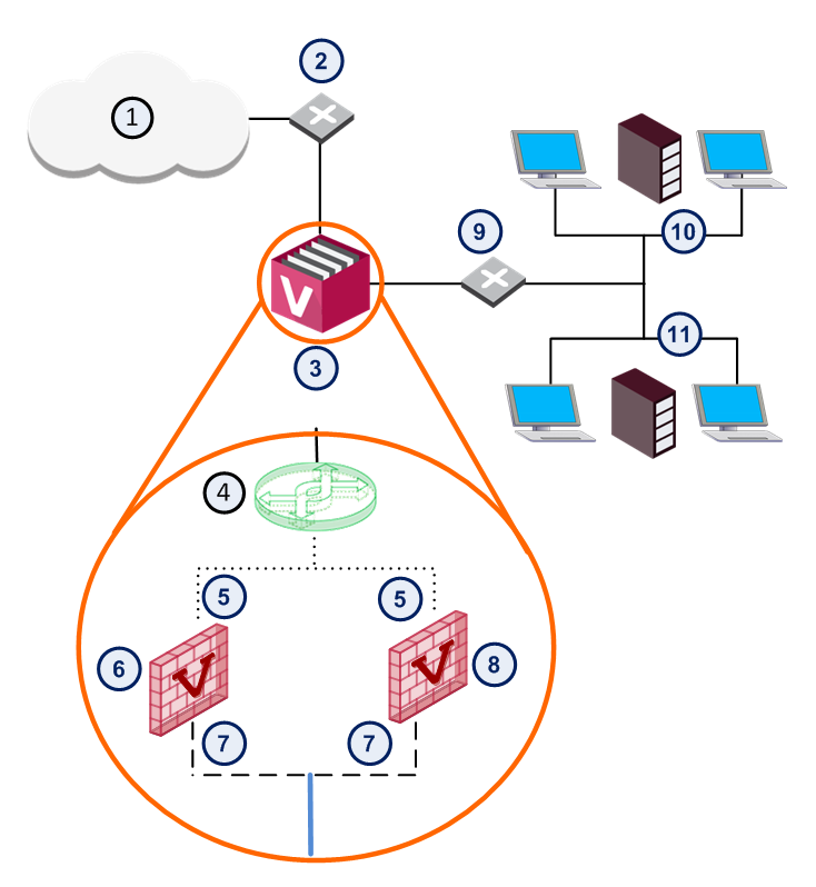
Here is an example of a typical VSX Gateway deployment with two Virtual Systems, each with two interfaces.
|
Item |
Description |
|
Item |
Description |
|---|---|---|---|---|
|
1 |
Internet |
|
8 |
Virtual System 2 |
|
2 |
Router |
|
9 |
VLAN Switch |
|
3 |
VSX Gateway |
|
10 |
Network 1 |
|
4 |
Virtual Switch |
|
11 |
Network 2 |
|
5 |
External Interface |
|
|
VLAN Interface |
|
6 |
Virtual System 1 |
|
|
VLAN Trunk |
|
7 |
Internal Interface |
|
|
Warp Link |


Creating a New Virtual System
You use the Virtual Systems Wizard to create a new Virtual System. Modify the initial definition and configure advanced options after you complete the wizard.
To start the Virtual System wizard:
-
Connect with SmartConsole to the Security Management Server or Target Domain Management Server that manages the new Virtual System.
-
From the left navigation panel, click Gateways & Servers.
-
Create a new Virtual System object in one of these ways:
-
From the top toolbar, click the New (
 ) > VSX > New Virtual System.
 -
In the top left corner, click Objects menu > More object types > Network Object > Gateways and Servers > VSX > New Virtual System.
-
In the top right corner, click Objects Pane > New > More > Network Object > Gateways and Servers > VSX > Virtual System.
The Virtual System Wizard opens.
-
-
Configure the applicable settings in the wizard as described below.
-
Install the applicable Access Control Policy on the new Virtual System object.
The General Properties wizard page defines the Virtual System object and the hosting VSX Gateway.
These are the parameters in this page:
-
Name: Unique, alphanumeric for the Virtual System. The name cannot contain spaces or special characters except the underscore.

Note - The name of the VSX Gateway or VSX Cluster object must not exceed 26 characters.
-
VSX Gateway / Cluster: Select the VSX Gateway that is hosting the Virtual System.
-
Bridge Mode: Select this option to create a Virtual System in the Bridge Mode.
In the Virtual System Network Configuration page, define internal and external interfaces and the IP address topology behind the internal interface.
|
|
Important - From R81.10, it is possible:
See Configuring Bridge Interfaces in Regular Virtual Systems. |
To configure the external and internal interfaces:
-
In the Interfaces section, configure the applicable interfaces.
You can add interfaces, delete, and change interfaces.
To add an interface, click Add, select an interface type from the list and configure its properties.
-
Select the Main IP Address from the list.
This IP address is usually assigned to the external interface and specifies the Virtual System address used with NAT or VPN connections.
To make an external IP address routable, select the external interface IP address as the main IP address.
-
Define network routing for your deployment.
Some routes are automatically defined by the interface definitions.
For example, you define a default gateway route leading to an external Virtual Router or to the Virtual System external interface.
To manually add a default route to the Routes table, click Add Default Routes.
Enter the default route IP address, or select the default Virtual Router.
The Route Configuration window opens.
-
Complete the definition.
Interfaces: To configure the external and internal interfaces, define interfaces and links to devices in the Interfaces section. You can add, change, and remove interfaces. To add an interface, click Add. The Interface Properties window opens. Select an interface from the list and define is properties.
Click Next and then click Finish to create the Virtual System.
Note that this may take several minutes to complete.
A message appears indicating successful or unsuccessful completion of the process.
If the process ends unsuccessfully, click View Report to view the error messages.
For further assistance, see VSX Diagnostics and Troubleshooting.
After you create a Virtual System using the Virtual System Wizard, you can modify the topology and all other parameters (except the name of the Virtual System) using the Virtual System Properties window.
Modifying a Virtual System
-
Connect with SmartConsole to the Security Management Server or Target Domain Management Server used to manage the Virtual System.
-
From the Gateways & Servers view or Object Explorer, double-click the Virtual System object.
-
Configure the applicable settings as described below.
-
Click OK to push the VSX Configuration.
-
Install the applicable Access Control Policy on the new Virtual System object.
The General Properties page lets you specify the main IP address and to enable various Check Point products for a Virtual System.
The Topology page contains definitions for Virtual System interfaces, routes and Warp Links. Based on these interface settings, VSX automatically creates routes to Virtual Devices and the VSX Gateway.
|
|
Note - If you modify the topology for a specific Virtual System in a cluster environment, the cluster topology is not updated until you install a policy on that Virtual System. |
-
Interfaces: The Interfaces section defines interfaces and links to devices. You can add new interfaces as well as delete and modify existing interfaces.
To add an interface, click New and select one of these options:
-
Regular - To select a physical interface
-
Leads to Virtual Router - To attach this Virtual System to a Virtual Router
-
Leads to Virtual Switch - To attach this Virtual System to a Virtual Switch
-
Bridge - From R81.10, it is possible to add bridge interfaces to regular Virtual Systems in SmartConsole. See Configuring Bridge Interfaces in Regular Virtual Systems.
The Interface Properties window opens. Select the interface from the list and define the appropriate properties. The sectionWorking with Interface Definitions and the SmartConsole online help provide explanations of the various properties and options.
Click Actions > Copy to Clipboard to copy the Interfaces table in CSV format.
-
-
Routes: To add a default route to the Routes table, click Add Default Routes and either enter an IP address or select a Virtual Router. The Route Configuration window opens. Click Help for details regarding the various properties and options. You can also add, change and remove routes (see Working with VSX Gateways).
-
Calculate topology automatically based on routing information: Enable this option to allow VSX to automatically calculate the network topology based on interface and routing definitions (enabled by default). VSX creates automatic links, or connectivity cloud objects linked to existing internal or external networks.
-
When this option is enabled, you cannot configure the topology using Topology tab in the Interface Properties window. These options are not available on the tab.
-
This option is not available in the Bridge Mode.
-
When employing dynamic routing, it is recommended to disable this option.
-
-
VPN Domain: The VPN Domain defines the set of hosts located behind a given Virtual System that communicate via a VPN tunnel with peer Virtual Systems. These options are only available if you selected VPN in the Check Point Products section on the General Properties page.
When including a Virtual Device as part of a VPN connection, you must specify a VPN Domain. The domain definition specifies Virtual System interfaces that are included in the VPN.
You can define a VPN Domain by enabling the applicable option:
-
All IP Addresses behind gateway based on topology information: Includes all hosts not located behind an external VSX Gateway interface.
-
Manually Defined: Includes all hosts in the selected network or group.
-
On the NAT > Advanced page, you configure NAT rules for packets originating from a Virtual System.
To enable and configure NAT for a Virtual System:
-
Select Add Automatic Address Translation.
-
Select a translation method:
-
Hide: Hide NAT only allows connections originating from the internal network. Internal hosts can access internal destinations, the Internet and other external networks. External sources cannot initiate a connection to internal network addresses.
-
Static: Static NAT translates each private address to a corresponding public address.
-
-
If you select Hide, select one of these options:
-
Hide behind Gateway hides the real IP address behind the Virtual System external interface IP address,
or
-
Hide behind IP Address hides the real address behind a virtual IP address, which is a routable, public IP address that does not belongs to any real machine.
-
-
If you selected Static NAT, enter the static IP address in the appropriate field.
-
Select the VSX Gateway from the Install on Gateway list.
In addition, see Working with Network Address Translation (NAT).
Configuring Bridge Interfaces in Regular Virtual Systems
-
Connect with SmartConsole to the Security Management Server or Target Domain Management Server that manages the Virtual System.
-
From the left navigation panel, click Gateways & Servers.
-
Open the Virtual System object.
-
From the left tree, click Topology.
-
In the Interfaces section, click New and select Bridge.
-
On the General tab, in the Interface field, select the first subordinate interface (for example,
eth2).On other tabs, configure the applicable settings and click OK.
-
In the Interfaces section, click New and select Bridge.
-
On the General tab, in the Interface field, select the second subordinate interface (for example,
eth3).On other tabs, configure the applicable settings and click OK.
-
Click OK to push the VSX Configuration.
-
Install the applicable Access Control Policy on the Virtual System object.
|
|
Important:
|
-
Connect with SmartConsole to the Security Management Server or Target Domain Management Server that manages the Virtual System.
-
From the left navigation panel, click Gateways & Servers.
-
Open the Virtual System object.
-
From the left tree, click Topology.
-
In the Interfaces section, select the bridge subordinate interface and click Edit.
-
Configure the applicable bridge interface settings.
-
Click OK to close the Interface Properties window.
-
Click OK to push the VSX Configuration.
-
Install the applicable Access Control Policy on the Virtual System object.
-
Determine the applicable bridge subordinate interfaces:
-
Connect to the command line on the VSX Gateway (each VSX Cluster Member).
On Scalable Platforms, you must connect to the Gaia Portal of the applicable Security Group.
-
Log in to Gaia Clish.
On Scalable Platforms, you must run the applicable commands in Gaia gClish of the applicable Security Group.
-
Go to the context of the Virtual System:
set virtual-system<VSID> -
Examine the bridge interfaces:
show bridging groups
-
-
Connect with SmartConsole to the Security Management Server or Target Domain Management Server that manages the Virtual System.
-
From the left navigation panel, click Gateways & Servers.
-
Open the Virtual System object.
-
From the left tree, click Topology.
-
In the Interfaces section:
-
Select the first bridge subordinate interface > click Delete > click OK to confirm.
-
Select the second bridge subordinate interface > click Delete > click OK to confirm.
-
-
Click OK to push the VSX Configuration.
-
Install the applicable Access Control Policy on the Virtual System object.
Deleting a Virtual System
To delete a Virtual System:
-
From the Gateways & Servers view or Object Explorer tree, right-click the Virtual System object and select Delete.
-
In the window that opens, click Yes.
Configuring DNS Servers on a Virtual System
Gaia uses the Domain Name Service (DNS) to translate host names into IP addresses.
To enable DNS lookups, you must enter the primary DNS server for your system. You can also enter secondary and tertiary DNS servers.
When the system resolves host names, it consults the primary name server. If a failure or time-out occurs, the system consults the secondary name server, and if necessary, the tertiary.
You can also define a DNS Suffix, which is a search for host-name lookup.
From R81, you can configure each Virtual System:
-
 To use specific DNS Servers for all DNS queries
A Virtual System uses the specific configured DNS servers for all DNS queries.
-
To use specific DNS Servers for DNS queries sent for specific Domains
A Virtual System uses the configured DNS Forwarding Domain.
The DNS Forwarding Domain determines the Domain Suffix and the DNS Servers for this Domain Suffix:
-
For all DNS queries that end with the Forwarding Domain Suffix, a Virtual System uses the specific DNS servers configured for this Forwarding Domain Suffix.
-
For all other DNS queries, a Virtual System uses other specific DNS servers configured in the Virtual System.
Note - If a Domain in a DNS query contains a shorter Domain as its suffix, then for all DNS queries that end with the longer Domain’s suffix a Virtual System uses the DNS servers configured to the longest Domain’s match. For example, if you configured the Domain Suffixes "
com" and "checkpoint.com" and their corresponding DNS servers, then for a DNS query with the suffix "support.checkpoint.com", a Virtual System uses the DNS server configured for the Domain Suffix "checkpoint.com" and not the DNS server configured for the Domain Suffix "com". -
-
To work as a DNS Relay
A Virtual System listens to DNS queries on specific interfaces and forwards them through all other interfaces (all these interfaces belong to the same Virtual System).
|
|
Important:
|
-
Connect to the command line on the VSX Gateway (each VSX Cluster Member).
On Scalable Platforms, you must connect to the Gaia Portal of the applicable Security Group.
-
Log in to Gaia Clish.
On Scalable Platforms, you must run the applicable commands in Gaia gClish of the applicable Security Group.
-
Enable ("
per-vs") or disable ("default") the feature:Note - You can run this command in the context of any Virtual Device.
set dns mode {per-vs | default} -
Show the status of the feature:
show dns mode -
Save the changes:
save config
-
Connect to the command line on the VSX Gateway (each VSX Cluster Member).
On Scalable Platforms, you must connect to the Gaia Portal of the applicable Security Group.
-
Log in to Gaia Clish.
On Scalable Platforms, you must run the applicable commands in Gaia gClish of the applicable Security Group.
-
Enable the feature:
set dns mode per-vsshow dns mode -
Go to the context of the applicable Virtual System:
set virtual-system <VSID> -
Configure the DNS Servers and the DNS Suffix:
set dns primary <IPv4 or IPv6 Address> secondary <IPv4 or IPv6 Address> tertiary <IPv4 or IPv6 Address> suffix <Name for Local Domain> -
Show the configured settings:
show dns -
Save the changes:
save config
set virtual-system <VSID>
delete dns
      primary
      secondary
      tertiary
      suffix
save config
|
set dns mode per-vs set virtual-system 1 set dns primary 192.168.10.21 set dns secondary 192.168.10.22 set dns tertiary 192.168.10.23 set dns suffix mycompany.com show dns save config |
-
Connect to the command line on the VSX Gateway (each VSX Cluster Member).
On Scalable Platforms, you must connect to the Gaia Portal of the applicable Security Group.
-
Log in to Gaia Clish.
On Scalable Platforms, you must run the applicable commands in Gaia gClish of the applicable Security Group.
-
Enable the feature:
set dns mode per-vsshow dns mode -
Go to the context of the applicable Virtual System:
set virtual-system <VSID> -
Configure the DNS Servers and the DNS Suffix for all DNS queries:
set dns primary <IPv4 or IPv6 Address> secondary <IPv4 or IPv6 Address> tertiary <IPv4 or IPv6 Address> suffix <Name for Local Domain> -
Show the configured settings for all DNS queries:
show dns -
Configure the Forwarding Domain Suffix:
add dns proxy forwarding-domain <Domain Suffix> -
Configure the DNS Servers for the specific Forwarding Domain Suffix:
set dns proxy forwarding-domain <Domain Suffix> primary <IPv4 or IPv6 Address> secondary <IPv4 or IPv6 Address> tertiary <IPv4 or IPv6 Address> -
Show the configured Forwarding Domain Suffixes:
show dns proxy forwarding-domains -
Show the configured settings for the specific Forwarding Domain Suffix:
show dns proxy forwarding-domain <Domain Suffix> primary secondary tertiary -
Save the changes:
save config
set virtual-system <VSID>
delete dns
      primary
      secondary
      tertiary
      suffix
save config
|
set virtual-system <VSID>
delete dns proxy forwarding-domain <Domain Suffix>
save config
|
set virtual-system <VSID>
delete dns proxy forwarding-domain <Domain Suffix>
      primary
      secondary
      tertiary
save config
|
set dns mode per-vs set virtual-system 1 set dns primary 192.168.10.21 set dns secondary 192.168.10.22 set dns tertiary 192.168.10.23 set dns suffix mycompany.com show dns add dns proxy forwarding-domain anothercompany.com set dns proxy forwarding-domain anothercompany.com primary 172.16.30.41 set dns proxy forwarding-domain anothercompany.com secondary 172.16.30.42 set dns proxy forwarding-domain anothercompany.com tertiary 172.16.30.43 show dns proxy forwarding-domains show dns proxy forwarding-domain anothercompany.com primary show dns proxy forwarding-domain anothercompany.com secondary show dns proxy forwarding-domain anothercompany.com tertiary save config |
-
Connect to the command line on the VSX Gateway (each VSX Cluster Member).
On Scalable Platforms, you must connect to the Gaia Portal of the applicable Security Group.
-
Log in to Gaia Clish.
On Scalable Platforms, you must run the applicable commands in Gaia gClish of the applicable Security Group.
-
Enable the feature:
set dns mode per-vsshow dns mode -
Go to the context of the applicable Virtual System:
set virtual-system <VSID> -
Configure the DNS Servers and the DNS Suffix for all DNS queries:
set dns primary <IPv4 or IPv6 Address> secondary <IPv4 or IPv6 Address> tertiary <IPv4 or IPv6 Address> suffix <Name for Local Domain> -
Show the configured settings:
show dns primary secondary tertiary suffix -
Configure the interfaces, on which the Virtual System must listen to DNS queries:
add dns proxy listening-interface <Name of Virtual System Interface> -
Show the configured listening interfaces:
show dns proxy listening-interfaces -
Save the changes:
save config
set virtual-system <VSID>
delete dns
      primary
      secondary
      tertiary
      suffix
save config
|
set virtual-system <VSID>
delete dns proxy listening-interface <Name of Virtual System Interface>
save config
|
set dns mode per-vs set virtual-system 1 set dns primary 192.168.10.21 set dns secondary 192.168.10.22 set dns tertiary 192.168.10.23 set dns suffix mycompany.com show dns add dns proxy listening-interface wrp128 show dns proxy listening-interfaces save config |
|
Parameter |
Description |
||
|---|---|---|---|
|
|
Enables (" |
||
|
|
Specifies the IPv4 or IPv6 address of the primary DNS server, which resolve host names. This must be a host that runs a DNS server. |
||
|
|
Specifies the IPv4 or IPv6 address of the secondary DNS server, which resolves host names if the primary server does not respond. This must be a host that runs a DNS server. |
||
|
|
Specifies the IPv4 or IPv6 address of the tertiary DNS server, which resolves host names if the primary and secondary servers do not respond. This must be a host that runs a DNS server. |
||
|
|
Specifies the name that is put at the end of all DNS searches if they fail. By default, it must be the local domain name. A valid domain name suffix is made up of subdomain strings separated by periods. Subdomain strings must begin with an alphabetic letter and can consist only of alphanumeric characters and hyphens. The domain name syntax is described in RFC 1035 (modified slightly in RFC 1223).
Example: You configured the DNS Suffix " |
||
|
|
Specifies the Forwarding Domain Suffix. The DNS Forwarding Domain determines the Domain Suffix and the DNS Servers for this Domain Suffix:
|
||
|
|
Specifies the name of a Virtual System interface, on which the Virtual System must listen to DNS queries. |
Configuring DHCP Server on a Virtual System
-
Connect to the command line on the VSX Gateway / each VSX Cluster Member.
On Scalable Platforms, you must connect to the Gaia Portal of the applicable Security Group.
-
Log in to Gaia Clish.
On Scalable Platforms, you must run the applicable commands in Gaia gClish of the applicable Security Group.
-
Go to the context of the applicable Virtual System:
set virtual-system <VS ID> -
Configure the required DHCP Server settings as described in the R82 Gaia Administration Guide > Chapter "Network Management" > Section "DHCP Server" > Section "Configuring a DHCP Server in Gaia Clish".