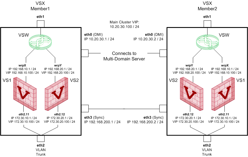
Example 2: VSX Cluster managed by Multi-Domain Server
This example shows:
-
One VSX
 Virtual System Extension. Check Point virtual networking solution, hosted on a computer or cluster with virtual abstractions of Check Point Security Gateways and other network devices. These Virtual Devices provide the same functionality as their physical counterparts. Cluster Two or more Security Gateways that work together in a redundant configuration - High Availability, or Load Sharing. in High Availability
 -
Two VSX Cluster Members with DMI management connection
-
Two Virtual Systems:
-
External interface on each Virtual System
Virtual Device on a VSX Gateway or VSX Cluster Member that implements the functionality of a Security Gateway. Acronym: VS. connects directly to the Virtual Switch -
Internal interface on each Virtual System connects to the VLAN Trunk interface
-
One Virtual System is configured with the IPsec VPN
Check Point Software Blade on a Security Gateway that provides a Site to Site VPN and Remote Access VPN access. Software Blade Specific security solution (module): (1) On a Security Gateway, each Software Blade inspects specific characteristics of the traffic (2) On a Management Server, each Software Blade enables different management capabilities. -
One Virtual System is configured with the Mobile Access
Check Point Software Blade on a Security Gateway that provides a Remote Access VPN access for managed and unmanaged clients. Acronym: MAB. Software Blade
-
-
-
One Main Domain Management Server
Check Point Single-Domain Security Management Server or a Multi-Domain Security Management Server. manages the objects of the VSX Cluster and Virtual Switch -
One Target Domain Management Server manages the object of the first Virtual System
-
One Target Domain Management Server manages the object of the second Virtual System
-
Related documentation:
Topology
|
Computer |
Interface |
IP Address / Net Mask |
Description |
|---|---|---|---|
|
VSX Cluster Member |
eth0 |
10.20.30.1/24 Main Cluster VIP 10.20.30.100/24 |
|
|
|
eth1 |
none |
External physical interface |
|
|
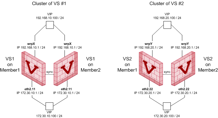
wrpX |
192.168.10.1/24 Cluster VIP 192.168.10.100/24 |
External warp interface on Virtual System 1 Note - Interface name is generated automatically |
|
|
wrpY |
192.168.20.1/24 VIP 192.168.20.100/24 |
External warp interface on Virtual System 2 Note - Interface name is generated automatically |
|
|
eth2 |
none |
Internal physical interface - VLAN Trunk |
|
|
eth2.11 |
172.30.10.1/24 Cluster VIP 172.30.10.100/24 |
Internal VLAN interface on Virtual System 1 |
|
|
eth2.22 |
172.30.20.1/24 Cluster VIP 172.30.10.100/24 |
Internal VLAN interface on Virtual System 2 |
|
|
eth3 |
192.168.200.1/24 |
Cluster Sync physical interface |
|
VSX Cluster Member 2 |
eth0 |
10.20.30.2/24 Cluster VIP 10.20.30.100/24 |
|
|
|
eth1 |
none |
External physical interface |
|
|
wrpX |
192.168.10.2/24 Cluster VIP 192.168.10.100/24 |
External warp interface on Virtual System 1 Note - Interface name is generated automatically |
|
|
wrpY |
192.168.20.2/24 Cluster VIP 192.168.20.100/24 |
External warp interface on Virtual System 2 Note - Interface name is generated automatically |
|
|
eth2 |
none |
Internal physical interface - VLAN Trunk |
|
|
eth2.11 |
172.30.10.2/24 Cluster VIP 172.30.10.100/24 |
Internal VLAN interface on Virtual System 1 |
|
|
eth2.22 |
172.30.10.2/24 Cluster VIP 172.30.10.100/24 |
Internal VLAN interface on Virtual System 2 |
|
|
eth3 |
192.168.200.2/24 |
Cluster Sync physical interface |
|
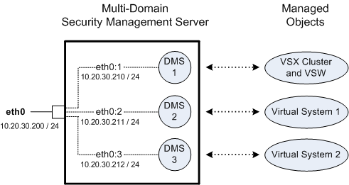
Multi-Domain Server |
eth0 |
10.20.30.200/24 |
Leading Interface that belongs to the Multi-Domain Server |
|
|
eth0:1 |
10.20.30.210/24 |
Virtual interface that belongs to the Main Domain Management Server (DMS 1), which manages the VSX Cluster and Virtual Switch |
|
|
eth0:2 |
10.20.30.211/24 |
Virtual interface that belongs to the Target Domain Management Server (DMS 2), which manages the Virtual System 1 |
|
|
eth0:3 |
10.20.30.212/24 |
Virtual interface that belongs to the Target Domain Management Server (DMS 3), which manages the Virtual System 2 |
Action Plan
-
Install the Multi-Domain Server
See the R80.40 Installation and Upgrade Guide.
Step
Instructions
A
Install a Check Point appliance or Open Server
Physical computer manufactured and distributed by a company, other than Check Point..B
C
Run the Gaia First Time Configuration Wizard.
These settings are specific to the Multi-Domain Server:
-
On the Management Connection page, select the applicable interface and configure the applicable IPv4 address.
In our example:
eth0, 10.20.30.200/24 -
On the first Installation Type page, select Multi-Domain Server.
-
On the second Installation Type page, select Primary Multi-Domain Server.
-
On the Leading VIP Interfaces Configuration page, select the applicable interface.
In our example:
eth0
D
Install the applicable licenses.
E
Configure the applicable settings:
-
Connect with SmartConsole
Check Point GUI application used to manage a Check Point environment - configure Security Policies, configure devices, monitor products and events, install updates, and so on. to the Multi-Domain Server. -
Configure the applicable settings.
-
Publish the SmartConsole session.
-
-
Create the Main Domain Management Server in SmartConsole to manage the VSX Cluster and Virtual Switch
Step
Instructions
A
Connect with SmartConsole to the Multi-Domain Server.
B
Create a new Domain and Domain Server.
In our example:
-
Name:
DMS1 -
IPv4:
10.20.30.210/24
C
From the left navigation panel, click Gateways & Servers.
D
Configure the Main Domain Management Server:
-
Connect with SmartConsole to the Main Domain Management Server (
DMS1). -
Configure the applicable Management Software Blades and settings.
-
Publish the SmartConsole session.
-
-
Create the Target Domain Management Server in SmartConsole to manage the Virtual System 1
Step
Instructions
A
Connect with SmartConsole to the Multi-Domain Server.
B
Create a new Domain and Domain Server.
In our example:
-
Name:
DMS2 -
IPv4:
10.20.30.211/24
C
From the left navigation panel, click Gateways & Servers.
D
Configure the Target Domain Management Server:
-
Connect with SmartConsole to the Target Domain Management Server (
DMS2). -
Configure the applicable Management Software Blades and settings.
-
Publish the SmartConsole session.
-
-
Create the Target Domain Management Server in SmartConsole to manage the Virtual System 2
Step
Instructions
A
Connect with SmartConsole to the Multi-Domain Server.
B
Create a new Domain and Domain Server.
In our example:
-
Name:
DMS3 -
IPv4:
10.20.30.212/24
C
From the left navigation panel, click Gateways & Servers.
D
Configure the Target Domain Management Server:
-
Connect with SmartConsole to the Target Domain Management Server (
DMS3). -
Configure the applicable Management Software Blades and settings.
-
Publish the SmartConsole session.
-
-
Install the VSX Cluster Member 1
See the R80.40 Installation and Upgrade Guide.
Step
Instructions
A
Install a Check Point appliance or Open Server.
B
Make sure you have enough physical interfaces for your VSX topology.
C Install Gaia OS.
D
Run the Gaia First Time Configuration Wizard.
These settings are specific to the VSX Cluster Member 1:
-
On the Management Connection page, select the interface for the DMI management connection and configure the applicable IPv4 address.
In our example:
eth0, 10.20.30.1/24 -
On the Internet Connection page, do not configure IP addresses on physical interfaces, to which your Virtual Systems connect directly.
-
On the Installation Type page, select Security Gateway and/or Security Management.
-
On the Products page, select Security Gateway.
-
On the Dynamically Assigned IP page, select No.
E
Make sure to enable the applicable physical interfaces:
To enable a physical interface in Gaia Portal
Web interface for the Check Point Gaia operating system.-
Connect to the Gaia Portal in your web browser.
In our example:
https://10.20.30.1 -
Click Network Management > Network Interfaces.
-
In the upper left corner, click the lock icon to obtain the configuration lock.
-
Select the applicable physical interface > click Edit.
-
Select Enable.
-
Click OK.
To enable a physical interface in Gaia Clish
The name of the default command line shell in Check Point Gaia operating system. This is a restricted shell (role-based administration controls the number of commands available in the shell)., run:-
set interface <Name of Physical Interface> state on -
save config
F
Install the applicable licenses.
-
-
Install the VSX Cluster Member 2
See the R80.40 Installation and Upgrade Guide.
Step
Instructions
A
Install a Check Point appliance or Open Server.
B
Make sure you have enough physical interfaces for your VSX topology.
C
Install Gaia OS.
D
Run the Gaia First Time Configuration Wizard.
These settings are specific to the VSX Cluster Member 1:
-
On the Management Connection page, select the interface for the DMI management connection and configure the applicable IPv4 address.
In our example:
eth0, 10.20.30.2/24 -
On the Internet Connection page, do not configure IP addresses on physical interfaces, to which your Virtual Systems connect directly.
-
On the Installation Type page, select Security Gateway and/or Security Management.
-
On the Products page, select Security Gateway.
-
On the Dynamically Assigned IP page, select No.
E
Make sure to enable the applicable physical interfaces:
To enable a physical interface in Gaia Portal
-
Connect to the Gaia Portal in your web browser.
In our example:
https://10.20.30.2 -
Click Network Management > Network Interfaces.
-
In the upper left corner, click the lock icon to obtain the configuration lock.
-
Select the applicable physical interface > click Edit.
-
Select Enable.
-
Click OK.
To enable a physical interface in Gaia Clish, run:
-
set interface <Name of Physical Interface> state on -
save config
F
Install the applicable licenses.
-
-
Create the VSX Cluster object with VSX Cluster Members in SmartConsole
See Configuring VSX Clusters and Working with VSX Clusters.
Step
Instructions
A
Connect with SmartConsole to the Main Domain Management Server that manages the objects of the VSX Cluster and Virtual Switch.
In our example:
DMS1B
At the top, click Objects > More object types > Network Object > Gateways and Servers > VSX > New Cluster.
C
On the VSX Cluster General Properties (Specify the object's basic settings) page:
-
In the Enter the VSX Cluster Name field, enter the applicable name for this object.
In our example:
MyVsxCluster -
In the Enter the VSX Cluster IPv4 field, enter the Cluster Virtual IPv4 address that is configured on the Dedicated Management Interfaces (DMI).
In our example:
10.20.30.100 -
In the Enter the VSX Cluster IPv6 field, enter the Cluster Virtual IPv6 address that is configured on the Dedicated Management Interfaces (DMI).
-
In the Select the VSX Cluster Version field, select the applicable Check Point version.
In our example:
R80.40 -
In the Select the VSX Cluster Platform field, select the applicable VSX Cluster mode:
-
ClusterXL - see Configuring a VSX Cluster in the High Availability Mode
-
ClusterXL Virtual System Load Sharing - see Configuring Virtual System Load Sharing
In our example:
ClusterXL -
-
Click Next.
D
On the VSX Cluster Members (Define the members of this VSX Cluster) page:
Add the first VSX Cluster Member:
-
Click Add.
-
In the Cluster Member Name field, enter the applicable name for this object.
In our example:
MyVsxMember1 -
In the Cluster Member IPv4 Address field, enter the IPv4 address of the Dedicated Management Interface (DMI).
In our example:
eth0,10.20.30.1 -
In the Enter the VSX Gateway IPv6 field, enter the applicable IPv6 address.
-
In the Activation Key field, enter the same Activation Key you entered during the First Time Configuration Wizard of this VSX Cluster Member.
-
In the Confirm Activation Key field, enter the same Activation Key again.
-
Click Initialize.
-
Click OK.
-
Enter the same Activation Key you entered in the
cpconfigmenu. -
Click Initialize.
If the Trust State field does not show Trust established, perform these steps:
-
Connect to the command line on the VSX Cluster Member.
-
Make sure there is a physical connectivity between the VSX Cluster Member and the Management Server (for example, pings can pass).
-
Run:
cpconfig -
Enter the number of this option:
Secure Internal Communication -
Follow the instructions on the screen to change the Activation Key.
-
On the VSX Cluster General Properties page, click Reset.
-
Enter the same Activation Key you entered in the
cpconfigmenu. -
Click Initialize.
E
On the VSX Cluster Members (Define the members of this VSX Cluster) page:
Add the second VSX Cluster Member:
-
Click Add.
-
In the Cluster Member Name field, enter the applicable name for this object.
In our example:
MyVsxMember2 -
In the Cluster Member IPv4 Address field, enter the IPv4 address of the Dedicated Management Interface (DMI).
In our example:
eth0,10.20.30.2 -
In the Enter the VSX Gateway IPv6 field, enter the applicable IPv6 address.
-
In the Activation Key field, enter the same Activation Key you entered during the First Time Configuration Wizard of this VSX Cluster Member.
-
In the Confirm Activation Key field, enter the same Activation Key again.
-
Click Initialize.
-
Click OK.
-
Click Next.
If the Trust State field does not show Trust established, perform these steps:
-
Connect to the command line on the VSX Cluster Member.
-
Make sure there is a physical connectivity between the VSX Cluster Member and the Management Server (for example, pings can pass).
-
Run:
cpconfig -
Enter the number of this option:
Secure Internal Communication -
Follow the instructions on the screen to change the Activation Key.
-
On the VSX Cluster General Properties page, click Reset.
-
Enter the same Activation Key you entered in the
cpconfigmenu. -
Click Initialize.
F
On the VSX Cluster Interfaces (Physical Interfaces Usage) page:
-
Examine the list of the interfaces - it must show all the physical interfaces on the VSX Gateway
Physical server that hosts VSX virtual networks, including all Virtual Devices that provide the functionality of physical network devices. It holds at least one Virtual System, which is called VS0.. -
If you plan to connect more than one Virtual System directly to same physical interface, you must select VLAN Trunk for that physical interface.
In our example:
eth2 -
Click Next.
G
On the VSX Cluster members (Synchronization Network) page:
-
Select the interface that will be used for state synchronization.
In our example:
eth3 -
Configure the IPv4 addresses for the Sync interfaces on each VSX Cluster Member.
In our example:
MyVsxMember1 - 192.168.200.1 / 255.255.255.0MyVsxMember2 - 192.168.200.2 / 255.255.255.0 -
Click Next.
H
On the Virtual Network Device Configuration (Specify the object's basic settings) page:
-
You can select Create a Virtual Network Device and configure the first applicable Virtual Network Device at this time (we recommend to do this later) - Virtual Switch or Virtual Router
Virtual Device on a VSX Gateway or VSX Cluster Member that functions as a physical router. Acronym: VR.. -
Click Next.
I
On the VSX Gateway Management (Specify the management access rules) page:
-
Examine the default access rules.
-
Select the applicable default access rules.
-
Configure the applicable source objects, if needed.
-
Click Next.
Important - These access rules apply only to the VSX Gateway (context of VS0), which is not intended to pass any "production" traffic.
J
On the VSX Gateway Creation Finalization page:
-
Click Finish and wait for the operation to finish.
-
Click View Report for more information.
-
Click Close.
K
Examine the VSX configuration:
-
Connect to the command line on each VSX Cluster Member.
-
Log in to Gaia Clish, or Expert mode.
-
Run:
vsx stat -v
-
-
Configure the VSX Cluster object in SmartConsole
See Working with VSX Clusters.
Step
Instructions
A
From the left navigation toolbar, click Gateways & Servers.
B
Open the VSX Cluster object.
In our example:
MyVsxClusterC
Enable the applicable Software Blades.
Refer to:
-
sk106496 - Software Blades updates on VSX R75.40VS and above - FAQ
-
Applicable Administration Guides on the R80.40 Home Page.
D
Configure other applicable settings.
E
Click OK to push the updated VSX Configuration.
Click View Report for more information.
F
Install policy on the VSX Cluster object:
-
Click Install Policy.
-
In the Policy field, select the default policy for this VSX Cluster object.
This policy is called:
<Name of VSX Cluster object>_VSX.In our example:
MyVsxCluster_VSX -
Click Install.
G
Examine the VSX configuration and VSX Cluster configuration:
-
Connect to the command line on each VSX Cluster Member.
-
Log in to Gaia Clish, or Expert mode.
-
Run:
vsx stat -v -
Run:
-
In Gaia Clish:
show cluster state -
In the Expert mode:
cphaprob state
-
-
Create the Virtual Switch object in SmartConsole
Step
Instructions
A
Connect with SmartConsole to the Main Domain Management Server that manages the objects of the VSX Cluster and Virtual Switch.
In our example:
DMS1B
Create the Virtual Switch object:
At the top, click Objects > More object types > Network Object > Gateways and Servers > VSX > New Virtual Switch.
C
On the VSX Switch General Properties (Define the object name and the hosting VSX) page:
-
In the Name field, enter the applicable name for this object.
In our example:
MyVsw -
In the VSX Gateway / Cluster field, select the applicable VSX Gateway or VSX Cluster object.
In our example:
MyVsxCluster -
Click Next.
D
On the VSX Switch Network Configuration (Define Virtual Switch Interfaces) page:
-
Click Add.
-
In the Interface field, select the applicable physical interface.
In our example:
eth2 -
Click OK.
-
Click Next.
E
On the VSX Switch Cluster Creation Finalization page:
-
Click Finish and wait for the operation to finish.
-
Click View Report for more information.
-
Click Close.
F
Examine the VSX configuration:
-
Connect to the command line on each VSX Cluster Member.
-
Log in to Gaia Clish, or Expert mode.
-
Run:
vsx stat -v
-
-
Create the first Virtual System object in SmartConsole
Step
Instructions
A
Connect with SmartConsole to the Target Domain Management Server that manages the object of the first Virtual System.
In our example:
DMS2B
In SmartConsole, create the first Virtual System object:
SeeWorking with Virtual Systems.
At the top, click Objects > More object types > Network Object > Gateways and Servers > VSX > New Virtual System.
C
On the VSX System General Properties (Define the object name and the hosting VSX) page:
-
In the Name field, enter the applicable name for this object.
In our example:
MyVs1 -
In the VSX Gateway / Cluster field, select the applicable VSX Gateway or VSX Cluster object.
In our example:
MyVsxCluster -
Click Next.
D
On the Virtual System Network Configuration (Define Virtual System Interfaces and Routes) page:
In our example, this Virtual System connects to the Virtual Switch ("external") and to the physical VLAN Trunk interface ("internal") on the VSX Cluster Members.
In the Interfaces section, add the "external" interface:
-
Click Add > Leads to Virtual Switch.
Add Interface window opens.
-
In the Leads to field, select the Virtual Switch your created earlier.
In our example:
MyVsxVsw -
In the IPv4 Configuration section, enter the applicable IP Address and Net Mask.
In our example:
192.168.10.1/24 -
In the IPv6 Configuration section, enter the applicable IPv6 Address and Prefix.
-
Click OK.
In the Interfaces section, add the "internal" interface:
-
Click Add > Regular.
-
In the Interface field, select the applicable physical interface - this is the "internal" interface.
In our example:
eth2(that is marked as VLAN Trunk) -
In the VLAN tag field, enter the applicable number between 2 and 4094.
In our example:
11(to configureeth2.11) -
In the IPv4 Configuration section, enter the applicable IP Address and Net Mask.
In our example:
172.30.10.1/24You can select Propagate route to adjacent Virtual Devices (IPv4) to "advertise" this Virtual System to neighboring Virtual Devices. This enables IPv4 connectivity between the neighboring Virtual Devices.
-
In the IPv6 Configuration section, enter the applicable IPv6 Address and Prefix.
You can select Propagate route to adjacent Virtual Devices (IPv6) to "advertise" this Virtual System to neighboring Virtual Devices. This enables IPv6 connectivity between the neighboring Virtual Devices.
-
Click OK.
In the Routes section, click Add to configure the applicable static routes and the Default Route.
Click Next.
E
On the Virtual System Cluster Creation Finalization page:
-
Click Finish and wait for the operation to finish.
-
Click View Report for more information.
-
Click Close.
F
Examine the VSX configuration:
-
Connect to the command line on each VSX Cluster Member.
-
Log in to Gaia Clish, or Expert mode.
-
Run:
vsx stat -v
-
-
Configure the first Virtual System object in SmartConsole
SeeWorking with Virtual Systems.
Step
Instructions
A
From the left navigation toolbar, click Gateways & Servers.
B
Open the first Virtual System object.
In our example:
MyVs1C
Enable the applicable Software Blades.
In our example:
IPsec VPNbladeRefer to:
-
sk106496 - Software Blades updates on VSX R75.40VS and above - FAQ
-
Applicable Administration Guides on the R80.40 Home Page.
D
Configure other applicable settings.
E
Click OK to push the updated VSX Configuration.
F
Configure and install the applicable policy on the first Virtual System object.
G
Examine the VSX configuration and VSX Cluster configuration:
-
Connect to the command line on each VSX Cluster Member.
-
Log in to Gaia Clish, or Expert mode.
-
Run:
vsx stat -v -
Run:
-
In Gaia Clish:
show cluster state -
In the Expert mode:
cphaprob state
-
-
Create the second Virtual System object in SmartConsole
Step
Instructions
A
Connect with SmartConsole to the Target Domain Management Server that manages the object of the first Virtual System.
In our example:
DMS3B
In SmartConsole, create the first Virtual System object:
SeeWorking with Virtual Systems.
At the top, click Objects > More object types > Network Object > Gateways and Servers > VSX > New Virtual System.
C
On the VSX System General Properties (Define the object name and the hosting VSX) page:
-
In the Name field, enter the applicable name for this object.
In our example:
MyVs2 -
In the VSX Gateway / Cluster field, select the applicable VSX Gateway or VSX Cluster object.
In our example:
MyVsxCluster -
Click Next.
D
On the Virtual System Network Configuration (Define Virtual System Interfaces and Routes) page:
In our example, this Virtual System connects to the Virtual Switch ("external") and to the physical VLAN Trunk interface ("internal") on the VSX Cluster Members.
In the Interfaces section, add the "external" interface:
-
Click Add > Leads to Virtual Switch.
-
In the Leads to field, select the Virtual Switch your created earlier.
In our example:
MyVsxVsw -
In the IPv4 Configuration section, enter the applicable IP Address and Net Mask.
In our example:
192.168.20.1/24 -
In the IPv6 Configuration section, enter the applicable IPv6 Address and Prefix.
-
Click OK.
In the Interfaces section, add the "internal" interface:
-
Click Add > Regular.
-
In the Interface field, select the applicable physical interface - this is the "internal" interface.
In our example:
eth2(that is marked as VLAN Trunk) -
In the VLAN tag field, enter the applicable number between 2 and 4094.
In our example:
22(to configureeth2.22) -
In the IPv4 Configuration section, enter the applicable IP Address and Net Mask.
In our example:
172.30.20.1/24You can select Propagate route to adjacent Virtual Devices (IPv4) to "advertise" this Virtual System to neighboring Virtual Devices. This enables IPv4 connectivity between the neighboring Virtual Devices.
-
In the IPv6 Configuration section, enter the applicable IPv6 Address and Prefix.
You can select Propagate route to adjacent Virtual Devices (IPv6) to "advertise" this Virtual System to neighboring Virtual Devices. This enables IPv6 connectivity between the neighboring Virtual Devices.
-
Click OK.
In the Routes section, click Add to configure the applicable static routes and the Default Route.
Click Next.
E
On the Virtual System Cluster Creation Finalization page:
-
Click Finish and wait for the operation to finish.
-
Click View Report for more information.
-
Click Close.
F
Examine the VSX configuration:
-
Connect to the command line on each VSX Cluster Member.
-
Log in to Gaia Clish, or Expert mode.
-
Run:
vsx stat -v
-
-
Configure the second Virtual System object in SmartConsole
SeeWorking with Virtual Systems.
Step
Instructions
A
From the left navigation toolbar, click Gateways & Servers.
B
Open the second Virtual System object.
In our example:
MyVs2C
Enable the applicable Software Blades.
In our example:
Mobile AccessbladeRefer to:
-
sk106496 - Software Blades updates on VSX R75.40VS and above - FAQ
-
Applicable Administration Guides on the R80.40 Home Page.
D
Configure other applicable settings.
E
Click OK to push the updated VSX Configuration.
F
Configure and install the applicable policy on the second Virtual System object.
G
Examine the VSX configuration and VSX Cluster configuration:
-
Connect to the command line on each VSX Cluster Member.
-
Log in to Gaia Clish, or Expert mode.
-
Run:
vsx stat -v -
Run:
-
In Gaia Clish:
show cluster state -
In the Expert mode:
cphaprob state
-