Working with Virtual Systems
This section presents procedures for creating and configuring Virtual Systems.
Introduction
The Virtual System![]() Virtual Device on a VSX Gateway or VSX Cluster Member that implements the functionality of a Security Gateway. Acronym: VS. definition process varies somewhat according to the template selected when creating the VSX Gateway
Virtual Device on a VSX Gateway or VSX Cluster Member that implements the functionality of a Security Gateway. Acronym: VS. definition process varies somewhat according to the template selected when creating the VSX Gateway![]() Physical server that hosts VSX virtual networks, including all Virtual Devices that provide the functionality of physical network devices. It holds at least one Virtual System, which is called VS0..
Physical server that hosts VSX virtual networks, including all Virtual Devices that provide the functionality of physical network devices. It holds at least one Virtual System, which is called VS0..
A typical Virtual System contains two interfaces:
-
External interface leading to external networks, a DMZ, or the Internet
-
Internal interface leading to internal networks or servers, often by means of a VLAN trunk
VSX![]() Virtual System Extension. Check Point virtual networking solution, hosted on a computer or cluster with virtual abstractions of Check Point Security Gateways and other network devices. These Virtual Devices provide the same functionality as their physical counterparts. supports up to 128 interfaces for each Virtual Device
Virtual System Extension. Check Point virtual networking solution, hosted on a computer or cluster with virtual abstractions of Check Point Security Gateways and other network devices. These Virtual Devices provide the same functionality as their physical counterparts. supports up to 128 interfaces for each Virtual Device![]() Logical object that emulates the functionality of a type of physical network object. Virtual Device can be on of these: Virtual Router, Virtual System, or Virtual Switch. and a total of up to 4096 interfaces per VSX Gateway or cluster
Logical object that emulates the functionality of a type of physical network object. Virtual Device can be on of these: Virtual Router, Virtual System, or Virtual Switch. and a total of up to 4096 interfaces per VSX Gateway or cluster![]() Two or more Security Gateways that work together in a redundant configuration - High Availability, or Load Sharing..
Two or more Security Gateways that work together in a redundant configuration - High Availability, or Load Sharing..
The supported interfaces include VLANs and Warp Links.
|
|
Note - By default, a Virtual System supports up to 64 interfaces. For more about how to increase the number of supported interfaces, see sk99121. |

You can add as many interfaces to a Virtual System as required, according to system resources.
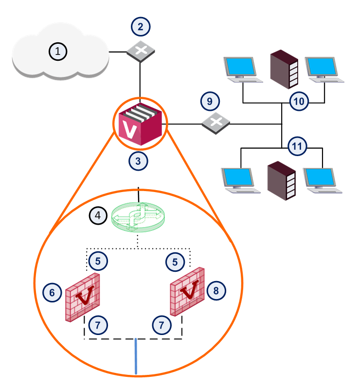
Here is an example of a typical VSX Gateway deployment with two Virtual Systems, each with two interfaces.
|
Item |
Description |
|
Item |
Description |
|---|---|---|---|---|
|
1 |
Internet |
|
8 |
Virtual System 2 |
|
2 |
Router |
|
9 |
VLAN Switch |
|
3 |
VSX Gateway |
|
10 |
Network 1 |
|
4 |
|
11 |
Network 2 |
|
|
5 |
External Interface |
|
|
VLAN Interface |
|
6 |
Virtual System 1 |
|
|
VLAN Trunk |
|
7 |
Internal Interface |
|
|


Creating a New Virtual System
You use the Virtual Systems Wizard to create a new Virtual System. Modify the initial definition and configure advanced options after you complete the wizard.
To start the Virtual System wizard:
-
Connect with SmartConsole
 Check Point GUI application used to manage a Check Point environment - configure Security Policies, configure devices, monitor products and events, install updates, and so on. to the Security Management Server Dedicated Check Point server that runs Check Point software to manage the objects and policies in a Check Point environment within a single management Domain. Synonym: Single-Domain Security Management Server. or Target Domain Management Server Check Point Single-Domain Security Management Server or a Multi-Domain Security Management Server. used to manage the new Virtual System.
 -
From the left navigation panel, click Gateways & Servers.
-
Create a new Virtual System object in one of these ways:
-
From the top toolbar, click the New (
 ) > VSX > New Virtual System.
 -
In the top left corner, click Objects menu > More object types > Network Object > Gateways and Servers > VSX > New Virtual System.
-
In the top right corner, click Objects Pane > New > More > Network Object > Gateways and Servers > VSX > Virtual System.
The Virtual System Wizard opens.
-
-
Configure the applicable settings in the wizard as described below.
-
Install the applicable Access Control Policy on the new Virtual System object.
The General Properties wizard page defines the Virtual System object and the hosting VSX Gateway.
These are the parameters in this page:
-
Name: Unique, alphanumeric for the Virtual System. The name cannot contain spaces or special characters except the underscore.
-
VSX Gateway / Cluster: Select the VSX Gateway that is hosting the Virtual System.
-
Bridge Mode: Select this option to create a Virtual System in the Bridge Mode
Security Gateway or Virtual System that works as a Layer 2 bridge device for easy deployment in an existing topology.. -
Override Creation Template: Select this option to override the creation template that was used for the initial configuration of the VSX Gateway.
In the Virtual System Network Configuration page, define internal and external interfaces and the IP address topology behind the internal interface. The process to define Virtual System network properties is different in different environments:
-
Use the VSX Gateway Creation template to define the VSX Gateway that contains the Virtual System.
-
If you choose to override the default VSX Gateway Creation template, you can use the Custom Configuration template.
-
You can create the Virtual System in Bridge Mode.
Note - Bridge mode is not available for a Virtual System created with the Shared Interface template.
The Virtual System Network Configuration page for the Shared Interface and Separate Interfaces templates appears as shown.
To configure the external and internal interfaces:
-
Select the applicable interfaces from the appropriate list.
-
If the selected Interface is a VLAN interface, enter the VLAN tag in the appropriate field. This field is not available for non-VLAN interfaces.
-
Enter the IP address and net mask in the appropriate fields. Optionally, enter a default gateway for the external interface.
-
Complete the definition process.
The Virtual System Network Configuration page for the Separate Interfaces template in the Bridge Mode opens.
To configure the external and internal interfaces:
-
Select the applicable interfaces for the internal and external networks from the appropriate list.
If the selected Interface is a VLAN interface, enter the same VLAN tag in both the external and internal VLAN Tag fields. This field is not available for non-VLAN interfaces.
-
Define the topology for the internal interface:
-
Select Not Defined if you do not wish to define an IP address.
-
Select Specific and then select an IP address definition from the list. IP address definitions can be based on object groups or predefined networks that define the topology.
-
-
To create a new IP address definition:
-
Select Specific, and click New.
-
Select Group to define an object group, or Network to define network properties.
-
-
Enable Layer 3 bridge interface monitoring to enable Layer 3 network fault detection for this Virtual System.
Enter an IP address and subnet mask, which continuously monitors the specified network for faults or connectivity issues.
The IP address/Subnet Mask define the network, on which the Virtual System resides.
-
Complete the definition process.
If you used the Custom Configuration template when creating the VSX Gateway, or if you selected Override Creation Template, manually define the network interfaces and connections. The Virtual System Network Configuration page for Custom Configuration opens.
To configure the external and internal interfaces:
-
In the interface table, define the applicable interfaces.
You can add new interfaces and delete and change existing interfaces.
To add an interface, click Add. The Interface Properties window opens. Select an interface from the list and define its properties.
-
Select the Main IP Address from the list.
This IP address is usually assigned to the external interface and specifies the Virtual System address used with NAT or VPN connections.
To make an external IP address routable, select the external interface IP address as the main IP address.
-
Define network routing for your deployment.
Some routes are automatically configured by the interface definitions.
For example, you define a default gateway route leading to an external Virtual Router
Virtual Device on a VSX Gateway or VSX Cluster Member that functions as a physical router. Acronym: VR. or to the Virtual System external interface.To manually add a default route to the Routes table, click Add Default Routes.
Enter the default route IP address, or select the default Virtual Router.
The Route Configuration window opens.
-
Complete the definition.
If you used the Custom Configuration template to create the VSX Gateway, or if you selected the Override Creation Template option for a Virtual System in Bridge Mode, then manually define the network interfaces.
Interfaces: To configure the external and internal interfaces, define interfaces and links to devices in the Interfaces table. You can add, change, and remove interfaces. To add an interface, click Add. The Interface Properties window opens. Select an interface from the list and define is properties.
Click Next and then click Finish to create the Virtual System.
Note that this may take several minutes to complete.
A message appears indicating successful or unsuccessful completion of the process.
If the process ends unsuccessfully, click View Report to view the error messages.
For further assistance, see VSX Diagnostics and Troubleshooting.
After you create a Virtual System using the Virtual System Wizard, you can modify the topology and all other parameters (except the name of the Virtual System) using the Virtual System Properties window.
Modifying a Virtual System
-
Connect with SmartConsole to the Security Management Server or Target Domain Management Server used to manage the Virtual System.
-
From the Gateways & Servers view or Object Explorer, double-click the Virtual System object.
-
Configure the applicable settings as described below.
-
Click OK to push the VSX Configuration.
-
Install the applicable Access Control Policy on the new Virtual System object.
The General Properties page lets you specify the main IP address and to enable various Check Point products for a Virtual System.
The Topology page contains definitions for Virtual System interfaces, routes and Warp Links. Based on these interface settings, VSX automatically creates routes to Virtual Devices and the VSX Gateway.
|
|
Note - If you modify the topology for a specific Virtual System in a cluster environment, the cluster topology is not updated until you install a policy on that Virtual System. |
-
Interfaces: The Interfaces section defines interfaces and links to devices. You can add new interfaces as well as delete and modify existing interfaces.
To add an interface, click New and select one of these options:
-
Regular - To select a physical interface
-
Leads to Virtual Router - To attach this Virtual System to a Virtual Router
-
Leads to Virtual Switch - To attach this Virtual System to a Virtual Switch
The Interface Properties window opens. Select the interface from the list and define the appropriate properties. The sectionWorking with Interface Definitions and the SmartConsole online help provide explanations of the various properties and options.
Click Actions > Copy to Clipboard to copy the Interfaces table in CSV format.
-
-
Routes: To add a default route to the Routes table, click Add Default Routes and either enter an IP address or select a Virtual Router. The Route Configuration window opens. Click Help for details regarding the various properties and options. You can also add, change and remove routes (see Working with VSX Gateways).
-
Calculate topology automatically based on routing information: Enable this option to allow VSX to automatically calculate the network topology based on interface and routing definitions (enabled by default). VSX creates automatic links, or connectivity cloud objects linked to existing internal or external networks.
-
When this option is enabled, you cannot configure the topology using Topology tab in the Interface Properties window. These options are not available on the tab.
-
This option is not available in the Bridge Mode.
-
When employing dynamic routing, it is recommended to disable this option.
-
-
VPN Domain: The VPN Domain defines the set of hosts located behind a given Virtual System that communicate via a VPN tunnel with peer Virtual Systems. These options are only available if you selected VPN in the Check Point Products section on the General Properties page.
When including a Virtual Device as part of a VPN connection, you must specify a VPN Domain. The domain definition specifies Virtual System interfaces that are included in the VPN.
You can define a VPN Domain by enabling the applicable option:
-
All IP Addresses behind gateway based on topology information: Includes all hosts not located behind an external VSX Gateway interface.
-
Manually Defined: Includes all hosts in the selected network or group.
-
On the NAT > Advanced page, you configure NAT rules for packets originating from a Virtual System.
To enable and configure NAT for a Virtual System:
-
Select Add Automatic Address Translation.
-
Select a translation method:
-
Hide: Hide NAT only allows connections originating from the internal network. Internal hosts can access internal destinations, the Internet and other external networks. External sources cannot initiate a connection to internal network addresses.
-
Static: Static NAT translates each private address to a corresponding public address.
-
-
If you select Hide, select one of these options:
-
Hide behind Gateway hides the real IP address behind the Virtual System external interface IP address,
or
-
Hide behind IP Address hides the real address behind a virtual IP address, which is a routable, public IP address that does not belongs to any real machine.
-
-
If you selected Static NAT, enter the static IP address in the appropriate field.
-
Select the VSX Gateway from the Install on Gateway list.
In addition, see Working with Network Address Translation (NAT).
Deleting a Virtual System
To delete a Virtual System:
-
From the Gateways & Servers view or Object Explorer tree, right-click the Virtual System object and select Delete.
-
In the window that opens, click Yes.