


|
|
|
A VSX Gateway processes traffic according to the following steps:
VSX incorporates VRF (Virtual Routing and Forwarding) technology that allows creation of multiple, independent routing domains on a single VSX Gateway or VSX Cluster. The independence of these routing domains makes possible the use of Virtual Devices with overlapping IP addresses. Each routing domain is known as a context.
When traffic arrives at a VSX Gateway, a process known as Context Determination directs traffic to the appropriate Virtual System, Virtual Router or Virtual Switch. The context determination process depends on the virtual network topology and the connectivity of the Virtual Devices.
The basic Virtual System connection scenarios are:
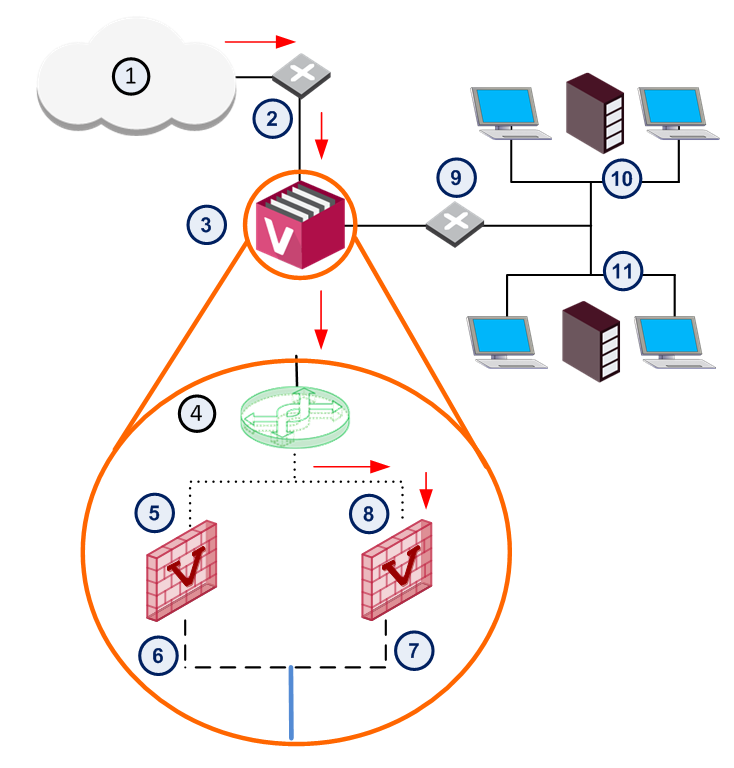
When traffic arrives at an interface (either physical or VLAN) that directly connects to a Virtual System, the connection itself determines the context and traffic passes directly to the appropriate Virtual System via that interface. This diagram shows traffic from a physical VLAN switch that is sent to an interface on the VSX Gateway.
Item |
Description |
|
Item |
Description |
|---|---|---|---|---|
1 |
Internet |
|
8 |
Virtual System 2 |
2 |
Router |
|
9 |
VLAN Switch |
3 |
VSX Gateway |
|
10 |
VLAN 100 |
4 |
Virtual Switch |
|
11 |
VLAN 200 |
5 |
Virtual System 1 |
|
|
VLAN Interface |
6 |
eth1.100 |
|
|
VLAN Trunk |
7 |
eth1.200 |
|
|
Warp Link |
VSX automatically directs traffic arriving via VLAN Interface eth1.200 to Virtual System 2 according to the context defined by the VLAN ID.
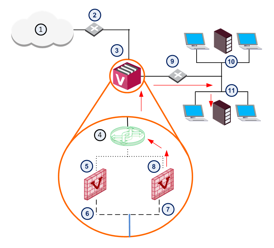
Traffic arriving via a Virtual Switch passes to the appropriate Virtual System based on the destination MAC address, as defined in the Virtual Switch forwarding table. Traffic arrives at the Virtual System via the Warp Link associated with the designated MAC address.
Item |
Description |
|
Item |
Description |
|---|---|---|---|---|
1 |
Internet |
|
8 |
MAC 00:12:C!:Ce:00:03 |
2 |
Router |
|
9 |
VLAN Switch |
3 |
VSX Gateway |
|
10 |
VLAN 100 |
4 |
Virtual Switch |
|
11 |
VLAN 200 |
5 |
MAC 00:12:C!:Ce:00:01 |
|
|
VLAN Interface |
6 |
Virtual System 1 |
|
|
VLAN Trunk |
7 |
Virtual System 2 |
|
|
Warp Link |
If the destination MAC address does not exist in the Virtual Switch forwarding table, the traffic is broadcast over all defined Warp Links. The Virtual Switch scenario is common for inbound traffic from external networks or the Internet.
Traffic arriving via a Virtual Router passes to the appropriate Virtual System based on entries in the Virtual Router routing table. Routing may be destination-based, source-based or both. Traffic arrives to the designated Virtual System via its Warp Link.

Item |
Description |
|
Item |
Description |
|---|---|---|---|---|
1 |
Internet |
|
8 |
172.69.22.30 |
2 |
Router |
|
9 |
VLAN Switch |
3 |
VSX Gateway |
|
10 |
VLAN 100 |
4 |
Virtual Router |
|
11 |
VLAN 200 |
5 |
172.23.10.11 |
|
|
VLAN Interface |
6 |
Virtual System 1 |
|
|
VLAN Trunk |
7 |
Virtual System 2 |
|
|
Warp Link |
Since each Virtual System functions as an independent Security Gateway, it maintains its own, unique security policy to protect the network behind it. The designated Virtual System inspects all traffic and allows or blocks it based on the rules contained in the security policy.
Each Virtual System maintains its own unique configuration and rules for processing and forwarding traffic to its final destination. This configuration also includes definitions and rules for NAT, VPN, and other advanced features.

