Print Download PDF Send Feedback

Previous

Next

NAT Rules

The NAT Rule Base has two sections that specify how the IP addresses are translated:

Each section in the NAT Rule Base is divided into cells that define the Source, Destination, and Service for the traffic.

Automatic and Manual NAT Rules

There are two types of NAT rules for network objects:

When you create manual NAT rules, it can be necessary to create the translated NAT objects for the rule.

Using Automatic Rules

You can enable automatic NAT rules for these SmartConsole objects:

SmartConsole creates two automatic rules for Static NAT, to translate the source and the destination of the packets.

For Hide NAT, one rule is created to translate the source of the packets.

For network and address range objects, SmartConsole creates a different rule to NOT translate intranet traffic. IP addresses for computers on the same object are not translated.

This table summarizes the NAT automatic rules:

Type of Traffic

Static NAT

Hide NAT

Internal to external

Rule translates source IP address

Rule translates source IP address

External to internal

Rule translates destination IP address

N/A (External connections are not allowed)

Intranet (for network and address range objects)

Rule does not translate IP address

Rule does not translate IP address

Order of NAT Rule Enforcement

The Firewall enforces the NAT Rule Base in a sequential manner. Automatic and manual rules are enforced differently. Automatic rules can use bidirectional NAT to let two rules be enforced for a connection.

SmartConsole organizes the automatic NAT rules in this order:

  1. Static NAT rules for Firewall, or host (computer or server) objects
  2. Hide NAT rules for Firewall, or host objects
  3. Static NAT rules for network or address range objects
  4. Hide NAT rules for network or address range objects

Sample Automatic Rules

Here are some sample automatic rules.

Static NAT for a Network Object
  1. Intranet connections in the HR network are not translated. The Firewall does not translate a connection between two computers that are part of the HR object.

    The Firewall does not apply rules 2 and 3 to traffic that matches rule 1.

  2. Connections from IP addresses from the HR network to any IP address (usually external computers) are translated to the Static NAT IP address.
  3. Connections from any IP address (usually external computers) to the HR are translated to the Static NAT IP address.
Hide NAT for Address Range
  1. Intranet connections in the Sales address range are not translated. The Firewall does not translate a connection between two computers that use IP addresses that are included in the Sales object.

    The Firewall does not apply rule 2 to traffic that matches rule 1.

  2. Connections from IP addresses from the Sales address range to any IP address (usually external computers) are translated to the Hide NAT IP address.

Configuring Static and Hide NAT

You can enable and configure NAT for SmartConsole objects.

Configuring Static NAT

When you enable Static NAT, each object is translated to a different IP address. SmartConsole can automatically create the NAT rules, or you can create them manually.

Configuring Hide NAT

Hide NAT uses different port numbers to identify the internal IP addresses. When you enable Hide NAT mode, the Firewall can translates the IP address to:

Note - You cannot use Hide NAT for these configurations:

Enabling Automatic NAT

SmartConsole can automatically create and configure the NAT rules for a network. Enable automatic NAT for every object, for which you are translating the IP address. Then configure the Access Control Rule Base to allow traffic to the applicable objects.

To enable automatic NAT:

  1. In SmartConsole, go to Gateways & Servers and double-click the gateway object.

    The General Properties window of the gateway opens.

  2. From the navigation tree, select NAT > Advanced.
  3. Select Add automatic address translation rules to hide this Gateway behind another Gateway.
  4. Select the Translation method: Hide or Static.
  5. Configure the NAT IP address for the object.
    • Hide behind Gateway - Use the IP address of the Security Gateway
    • Hide behind IP address - Enter the IP address.
  6. Click Install on Gateway and select All or the Security Gateway that translates the IP address.
  7. Click OK.

After you enable and configure NAT on all applicable gateways, install the policy.

Automatic Hide NAT to External Networks

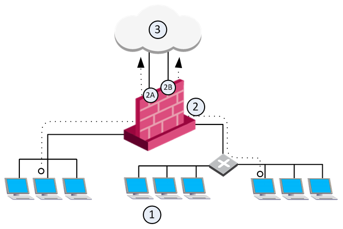
For large and complex networks, it can be impractical to configure the Hide NAT settings for all the internal IP addresses. An easy alternative is to enable a Firewall to automatically Hide NAT for all traffic with external networks. The Firewall translates all traffic that goes through an external interface to the valid IP address of that interface.

In this sample configuration, computers in internal networks open connections to external servers on the Internet. The source IP addresses of internal clients are translated to the IP address of an external interface.

Automatic_Hide_NAT_to_External_Networks

Item

Description

1

Internal networks

2

Security Gateway - Firewall is configured with automatic Hide NAT.

2A and 2B

Two external interfaces 192.0.2.1 and 192.0.2.100.

1 -->3

External computers and servers on the Internet

Source IP addresses are translated to the applicable external interface IP address: 192.0.2.1 or 192.0.2.100.

Note - If a connection matches a regular NAT rule and a NAT-for-internal-networks rule, the regular NAT rule takes precedence.

To enable automatic Hide NAT:
  1. In SmartConsole, go to Gateways & Servers and double-click the gateway object.

    The General Properties window of the gateway opens.

  2. From the navigation tree, select NAT.
  3. Select Hide internal networks behind the Gateway's external IP.
  4. Click OK.
  5. Install the policy.

Enabling Manual NAT

For some deployments, it is necessary to manually define the NAT rules. Create SmartConsole objects that use the valid (NATed) IP addresses. Create NAT rules to translate the original IP addresses of the objects to valid IP addresses. Then configure the Firewall Rule Base to allow traffic to the applicable translated objects with these valid IP addresses.

Note - For manual NAT rules, it is necessary to configure Proxy ARP entries to associate the translated IP address.

These are some situations that must use manual NAT rules:

This procedure explains how to configure manual Static NAT for a web server. You can also configure manual Hide NAT for SmartConsole objects.

To enable manual Static NAT, follow this workflow:

  1. Create a clone from the network object, for example, the Web server.
  2. Add a NAT rule that maps the original object to the NATed one.
  3. Add Access Control rules that allow traffic to the new NATed objects.

To create a clone network object:

  1. In SmartConsole, right-click the object and select Clone.

    The General Properties window of the new object opens.

  2. Enter the Name. We recommend that you name the object <name>_valid_address.
  3. Enter the NATed IP address.
  4. Click OK.

To add a NAT rule to the Rule Base:

  1. In SmartConsole, go to Security Policies > Access Control > NAT.
  2. Add a manual rule above the automatic NAT rules.
  3. Configure the manual rule to translate the IP address. For example:
    • Original Source - WebServer
    • Translated Source - WebServer_valid_address

To add Access Control rules:

  1. In SmartConsole, go to Security Policies > Access Control > Policy.
  2. Add rules that allow traffic to the applicable NATed objects.

    These objects are the cloned objects that are called <name>_valid_address.

  3. Install the policy.

Sample Deployment (Static and Hide NAT)

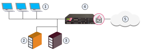
The goal for this sample deployment is to configure:

Sample_Deployment_(Static_and_Hide_NAT)

Item

Description

1

Internal computers (Alaska_LAN 2001:db8::/64)

2

Web server (Alaska.Web 2001:db8:0:10::5 translated to 2001:db8:0:a::5)

3

Mail server (Alaska.Mail 2001:db8:0:10::6 translated to 2001:db8:0:a::6)

4

Security Gateway (External interface 2001:db8:0:a::1)

5

External computers and servers in the Internet

To configure NAT for the network:

  1. Enable automatic Static NAT for the web server.
    1. Double-click the Alaska.Web object and select NAT.
    2. Select Add Automatic Address Translation Rules.
    3. In Translation method, select Static.
    4. Select Hide behind IP Address and enter 2001:db8:0:a::5.
    5. Click OK.
  2. Enable automatic Static NAT for the mail server.
    1. Double-click the Alaska.Mail object and select NAT.
    2. Select Add Automatic Address Translation Rules.
    3. In Translation method, select Static.
    4. Select Hide behind IP Address and enter 2001:db8:0:a::6.
    5. Click OK.
  3. Enable automatic Hide NAT for the internal computers.
    1. Double-click the Alaska_LAN object and select NAT.
    2. Select Add Automatic Address Translation Rules.
    3. In Translation method, select Hide.
    4. Select Hide behind Gateway.
  4. Click OK and then install the policy.

Sample Deployment (Manual Rules for Port Translation)

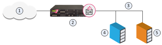
The goal for this sample configuration is to let external computers access a web and mail server in a DMZ network from one IP address. Configure Hide NAT for the DMZ network object and create manual NAT rules for the servers.

Manual_NAT_Rules_for_Port_Translation

Item

Description

1

External computers and servers in the Internet

2

Security Gateway (Alaska_GW external interface 2001:db8:0:c::1)

3

DMZ network (Alaska_DMZ 2001:db8:a::/128)

4

Web server (Alaska_DMZ_Web 2001:db8:a::35:5 translated to 2001:db8:0:c::1)

5

Mail server (Alaska_DMZ_Mail 2001:db8:a::35:6 translated to 2001:db8:0:c::1)

To configure NAT for the DMZ servers:

  1. Enable automatic Hide NAT for the DMZ network.
    1. Double-click the Alaska_DMZ object and select NAT.
    2. Select Add Automatic Address Translation Rules.
    3. In Translation method, select Hide.
    4. Select Hide behind Gateway.
    5. Click OK.
  2. Create a manual NAT rule that translates HTTP traffic from the Security Gateway to the web server.
    1. In SmartConsole, go to Security Policies > Access Control > NAT.
    2. Add a rule below the automatic rules.
    3. Right-click the cell and select Add new items to configure these settings:
      • Original Destination - Alaska_GW
      • Original Service - HTTP
      • Translated Destination - Alaska_DMZ_Web
  3. Create a manual NAT rule that translates SMTP traffic from the Security Gateway to the mail server.
    1. Add a rule below the automatic rules.
    2. Right-click the cell and select Add new items to configure these settings:
      • Original Destination - Alaska_GW
      • Original Service - SMTP
      • Translated Destination - Alaska_DMZ_Web
  4. Create a rule in the Firewall Rule Base that allows traffic to the servers.
    1. In SmartConsole, go to Security Policies > Access Control > NAT.
    2. Add a rule to the Rule Base.
    3. Right-click the cell and select Add new items to configure these settings:
      • Destination - Alaska_DMZ
      • Service - HTTP, SMTP
      • Action - Allow
  5. Install the policy.

NAT Rule Base for Manual Rules for Port Translation Sample Deployment

No.

Original Source

Original Destination

Original Services

Translated Source

Translated Destination

Translated Services

Install On

Comments

1

Alaska_DMZ

Alaska_DMZ

Any

Original

Original

Original

All

Automatic rule

2

Alaska_DMZ

Any

Any

H Alaska_DMZ (Hiding Address)

Original

Original

All

Automatic rule

3

Any

Alaska_GW

http

Original

S Alaska_DMZ_Web

Original

Policy Targets


4

Any

Alaska_GW

smtp

Original

S Alaska_DMZ_Mail

Original

Policy Targets


Configuring Stateful NAT64 (IPv6 to IPv4 translation)

R80.30 supports NAT64 rules.

Background:

NAT64 translation (RFC 6146) lets IPv6-only client communicate with IPv4-only server using unicast UDP, TCP, or ICMP.

IPv6-only client is one of these:

IPv4-only server is one of these:

The translation of IP addresses is done by translating the packet headers according to the IP/ICMP Translation Algorithm defined in RFC 6145. The IPv4 addresses of IPv4 hosts are translated to and from IPv6 addresses using the algorithm defined in RFC 6052, and an IPv6 prefix assigned to the stateful NAT64 for this specific purpose.

Note - For information about DNS64, see RFC 6147.

Properties of Stateful NAT64:

NAT64 use case scenarios:

R80.30 supports these standards for NAT64:

R80.30 does not support these features for NAT64:

Workflow for configuring NAT64 rules:

  1. Prepare your Security Gateway for NAT64.
  2. Define the NAT64 rules.
  3. Configure the additional settings for NAT64.

Preparing Security Gateway for NAT64

To prepare a Security Gateway for NAT64:

Note - In cluster, do these steps on each cluster member.

Step

Instructions

1

Make sure that an IPv6 address is assigned to the interface that connects to the destination IPv4 network, and the IPv6 network prefix length is equal to, or less than 96.

Note - This can be any valid IPv6 address with the IPv6 network prefix length equal to, or less than 96.

  • In Gaia Portal:

    Click Network Management > Network Interfaces.

  • In Gaia Clish:

    Run: show interface <Name of Interface> ipv6-address

If such IPv6 address is not assigned yet, assign it now. For details, see R80.30 Gaia Administration Guide - Chapter Network Management - Section Network Interfaces - Section Physical Interfaces.

2

Make sure that the IPv6 routing is configured to send the traffic that is destined to the NATed IPv6 addresses (defined in the Original Destination column in the NAT64 rule) through the interface that connects to the destination IPv4 network.

  • In Gaia Portal:

    Click Advanced Routing > Routing Monitor.

  • In Gaia Clish:

    Run: show ipv6 route

If such route does not already exist, add it in Gaia Clish. For details, see R80.30 Gaia Administration Guide. Run these commands in Gaia Clish:

  1. set ipv6 static-route <NATed Destination IPv6 Addresses>/<96 or less> nexthop gateway <Any IPv6 Address from the IPv6 subnet of the Interface that connects to the destination real IPv4 network> on

    Example topology:

    [IPv6 Client] --- (NATed IPv6 of IPv4 side are 1111:2222::/96) [Security Gateway] (eth3 with IPv6 3333:4444::1) --- [IPv4 Server]

    In such case, configure the IPv6 route using this command:

    set ipv6 static-route 1111:2222::/96 nexthop gateway 3333:4444::10 on

  2. save config

3

Make sure that the number of IPv6 CoreXL FW instances is equal to the number of IPv4 CoreXL FW instances.

  1. Connect to the command line on the Security Gateway.
  2. Log in to Gaia Clish, or Expert mode.
  3. Show the number of IPv6 CoreXL FW instances. Run:

    fw6 ctl multik stat

  4. Show the number of IPv4 CoreXL FW instances. Run:

    fw ctl multik stat

  5. If the number of IPv6 CoreXL FW instances is less than the number of IPv4 CoreXL FW instances, then do these steps:
    1. Run:

      cpconfig

    2. Select Check Point CoreXL
    3. Select Change the number of IPv6 firewall instances
    4. Configure the number of IPv6 CoreXL FW instances to be the same as the number of IPv4 CoreXL FW instances
    5. Select Exit
    6. Reboot the Security Gateway
  6. Connect to the command line on the Security Gateway.
  7. Log in to Gaia Clish, or Expert mode.
  8. Show the number of IPv6 CoreXL FW instances. Run:

    fw6 ctl multik stat

  9. Show the number of IPv4 CoreXL FW instances. Run:

    fw ctl multik stat

Example output:

[Expert@GW:0]# fw6 ctl multik stat

ID | Active | CPU | Connections | Peak

----------------------------------------------

0 | Yes | 3 | 0 | 0

1 | Yes | 2 | 0 | 4

2 | Yes | 1 | 0 | 2

[Expert@GW:0]#

[Expert@GW:0]# fw ctl multik stat

ID | Active | CPU | Connections | Peak

----------------------------------------------

0 | Yes | 3 | 10 | 14

1 | Yes | 2 | 6 | 15

2 | Yes | 1 | 7 | 15

[Expert@GW:0]#

Defining NAT64 Rules

Define NAT64 rules as Manual NAT rules in the Access Policy. Make sure that you add access rules that allow this NAT traffic.

Do these steps in SmartConsole to define NAT64 rules:

  1. Define a source IPv6 Network object.

    This object represents the source IPv6 addresses, which you translate to source IPv4 addresses.

  2. Define a translated destination IPv6 Network object with an IPv4-embedded IPv6 address, or a translated destination IPv6 Host object with a static IPv6 address.

    This object represents the translated destination IPv6 address, to which the IPv6 sources connect.

  3. Define a translated source IPv4 Address Range object.

    This object represents the translated source IPv4 addresses, to which you translate the original source IPv6 addresses.

  4. Create a Manual NAT64 rule.
  5. Install the Access Policy.

To define a source IPv6 Network object that represents the source IPv6 address, which you translate to source IPv4 addresses:

  1. Click Objects menu > New Network.
  2. In the Object Name field, enter the applicable name.
  3. In the Comment field, enter the applicable text.
  4. Click the General page of this object.
  5. In the IPv4 section:

    Do not enter anything.

  6. In the IPv6 section:
    1. In the Network address field, enter the IPv6 address of your IPv6 network, which you translate to source IPv4 addresses.
    2. In the Prefix field, enter the prefix of your IPv6 network.
  7. On the NAT page of this object:

    Do not configure anything.

  8. Click OK.

To define a translated destination IPv6 Network object with IPv4-embedded IPv6 address that represents the IPv6 addresses, to which the IPv6 sources connect:

  1. Click Objects menu > New Network.
  2. In the Object Name field, enter the applicable name.
  3. In the Comment field, enter the applicable text.
  4. Click the General page of this object.
  5. In the IPv4 section:

    Do not enter anything.

  6. In the IPv6 section:
    1. In the Network address field, enter the destination IPv4-embedded IPv6 address (also called IPv4-mapped IPv6 address), to which the IPv6 sources connect.

      Such IPv6 address contains (from left to right) 80 "zero" bits, followed by 16 "one" bits, and then the 32 bits of the IPv4 address - 0:0:0:0:0:FFFF:X.Y.Z.W, where X.Y.Z.W are the four octets of the destination IPv4 address.

      For example, for IPv4 network 192.168.3.0, the IPv4-embedded IPv6 address is 0:0:0:0:0:FFFF:192.168.3.0, or 0:0:0:0:0:FFFF:C0A8:0300. For more information, see RFC 6052.

      These IPv4-embedded IPv6 addresses are published by an external DNS64 server.

    2. In the Prefix field, enter the applicable IPv6 prefix.

    Note - You can define IPv4-embedded IPv6 addresses only for these object types: Address Range, Network, and Host.

  7. On the NAT page of this object:

    Do not configure anything.

  8. Click OK.

To define a translated destination IPv6 Host object with static IPv6 address that represents the IPv6 address, to which the IPv6 sources connect:

  1. Click Objects menu > New Host.
  2. In the Object Name field, enter the applicable name.
  3. In the Comment field, enter the applicable text.
  4. Click the General page of this object.
  5. In the IPv4 section:

    Do not enter anything.

  6. In the IPv6 section:

    In the Network address field, enter the destination static IPv6 address, to which the IPv6 sources connect.

  7. On the NAT page of this object:

    Do not configure anything.

  8. Configure the applicable settings on other pages of this object.
  9. Click OK.

To define a translated source IPv4 Address Range object that represents the IPv4 addresses, to which you translate the source IPv6 addresses:

  1. Click Objects menu > More object types > Network Object > Address Range > New Address Range.
  2. In the Object Name field, enter the applicable name.
  3. In the Comment field, enter the applicable text.
  4. Click the General page of this object.
  5. In the IPv4 section:
    1. In the First IP address field, enter the first IPv4 address of your IPv4 addresses range, to which you translate the source IPv6 addresses.
    2. In the Last IP address field, enter the last IPv4 address of your IPv4 addresses range, to which you translate the source IPv6 addresses.

    Notes:

    • This IPv4 addresses range must not use private IPv4 addresses (see RFC 1918 and Menu > Global properties > Non Unique IP Address Range).
    • This IPv4 addresses range must not be used on the IPv4 side of the network.
    • We recommend that you define a large IPv4 addresses range for more concurrent NAT64 connections.
  6. In the IPv6 section:

    Do not enter anything.

  7. On the NAT page of this object:

    Do not configure anything.

  8. Click OK.

To create a Manual NAT64 rule:

  1. From the left Navigation Toolbar, click Security Policies.
  2. In the top Access Control section, click NAT.
  3. Right-click on the Manual Lower Rules section title, and near the New Rule, click Above or Below.
  4. Configure this Manual NAT64 rule:

    Important - Some combinations of object types are not supported in the Original Source and Original Destination columns. See the summary table with the supported NAT rules at the bottom of this section.

    1. In the Original Source column, add the IPv6 object for your original source IPv6 addresses.

      In this rule column, NAT64 rules support only these types of objects:

      • *Any
      • Host with a static IPv6 address
      • Address Range with IPv6 addresses
      • Network with IPv6 address
    2. In the Original Destination column, add a translated destination IPv6 object with an IPv4-embedded IPv6 address.

      In this rule column, NAT64 rules support only these types of objects:

      • Host with a static IPv6 address
      • Address Range with IPv4-embedded IPv6 addresses
      • Network with an IPv4-embedded IPv6 address
    3. In the Original Services column, you must leave the default Any.
    4. In the Translated Source column, add the IPv4 Address Range object for your translated source IPv4 addresses range.

      In this rule column, NAT64 rules support only these types of objects:

      • Host with a static IPv4 address, only if in the Original Source column you selected a Host with a static IPv6 address
      • Address Range with IPv4 addresses
    5. In the Translated Source column, right-click the IPv4 Address Range object > click NAT Method > click Stateful NAT64:
      • The Translated Packet Destination column shows = Embedded IPv4 Address.
      • The 64 icon shows in both the Translated Source and Translated Destination columns.

      In this rule column, NAT64 rule supports only these types of objects:

      • Host with a static IPv4 address, only if in the Original Source column you selected a Host with a static IPv6 address
      • Embedded IPv4 Address
    6. In the Translated Services column, you must leave the default = Original.
  5. Publish the session and install the Access Policy.

To summarize, you must configure only these Manual NAT64 rules (rule numbers are for convenience only):

#

Original
Source

Original
Destination

Original
Services

Translated
Source

Translated
Destination

Translated
Services

1

*Any

IPv6
Host
object with
a static
IPv6 address

*Any

IPv4
Address
Range
object

IPv4
Host
object

= Original

2

*Any

IPv6
Address Range
object with an
IPv4-embedded
IPv6 addresses

*Any

IPv4
Address
Range
object

Embedded
IPv4
Address

= Original

3

*Any

IPv6
Network
object with an IPv4-embedded
IPv6 address

*Any

IPv4
Address
Range
object

Embedded
IPv4
Address

= Original

4

IPv6
Host
object
with
a static
IPv6
address

IPv6
Host
object with
a static
IPv6 address

*Any

IPv4
Host
object

IPv4
Host
object

= Original

5

IPv6
Host
object
with
a static
IPv6
address

IPv6
Address Range
object with
IPv4-embedded
IPv6 addresses

*Any

IPv4
Address
Range
object

Embedded
IPv4
Address

= Original

6

IPv6
Host
object
with
a static
IPv6
address

IPv6
Network
object with an
IPv4-embedded
IPv6 address

*Any

IPv4
Address
Range
object

Embedded
IPv4
Address

= Original

7

IPv6
Address
Range
object

IPv6
Host
object with
a static
IPv6 address

*Any

IPv4
Address
Range
object

IPv4
Host
object

= Original

8

IPv6
Address
Range
object

IPv6
Address Range
object with
IPv4-embedded
IPv6 addresses

*Any

IPv4
Address
Range
object

Embedded
IPv4
Address

= Original

9

IPv6
Address
Range
object

IPv6
Network
object with an
IPv4-embedded
IPv6 address

*Any

IPv4
Address
Range
object

Embedded
IPv4
Address

= Original

10

IPv6
Network
object

IPv6
Host
object with
a static
IPv6 address

*Any

IPv4
Address
Range
object

IPv4
Host
object

= Original

11

IPv6
Network
object

IPv6
Address Range
object with
IPv4-embedded
IPv6 addresses

*Any

IPv4
Address
Range
object

Embedded
IPv4
Address

= Original

12

IPv6
Network
object

IPv6
Network
object with an
IPv4-embedded
IPv6 address

*Any

IPv4
Address
Range
object

Embedded
IPv4
Address

= Original

Configuring the Additional Settings for NAT64

You can configure the additional settings that control the NAT64 translation mechanism. These settings are compliant with RFC 6145.

Note - We recommend that you change the default settings only if you are familiar with the technology.

  1. Close all SmartConsole windows.
  2. Connect with GuiDBedit Tool to the applicable Security Management Server or Domain Management Server.
  3. In the top left section, click Table > Global Properties > properties.
  4. In the top right section, click firewall_properties.
  5. In the bottom section, scroll to these Field Names:
    • nat64_add_UDP_checksum
    • nat64_avoid_PMTUD_blackhole
    • nat64_copy_type_of_service
    • nat64_error_message_on_dropped_packets
  6. Right-click on the applicable Field Name and click Edit.
  7. Select the applicable Value (true, or false) and click OK.

    Field Name

    Description

    nat64_add_UDP_checksum

    This setting controls whether the translator should calculate and add a valid UDP checksum value to a packet, if the packet checksum value is zero.

    This is important because, by default, an IPv4 UDP packet with a checksum value of zero is dropped on the IPv6 side.

    Default: false

    nat64_avoid_PMTUD_blackhole

    This setting controls whether to allow packet fragmentation on the IPv4 (destination) side during PMTU discovery.

    Enable this setting if some equipment combinations cause PMTU discovery to fail.

    Default: false

    nat64_copy_type_of_service

    This setting controls whether to copy the traffic Class Field to the Type Of Service field, and set the Type Of Service field in the translated packet to zero.

    Default: true

    nat64_error_message_on_dropped_packets

    This setting controls whether to generate an audit log after a connection is closed.

    For each closed connection, the log shows:

    • Connection information (source and destination IP address, source port, and service).
    • Translated source IP address and source port.
    • Start time and end time.
    • If the connection was closed because the connection expired, log shows additional information in the TCP End Reason field.

      If this field does not show in the log, the connection was closed with a TCP RST, or with a TCP FIN, and did not expire.

    Default: true

  8. Click File > Save All to save the changes.
  9. Close the GuiDBedit Tool.
  10. Connect with the SmartConsole to the applicable Security Management Server or Domain Management Server.
  11. Install the Access Policy.

Logging of NAT64 traffic

In the Security Gateway log for NAT64 connection, the source and destination IPv6 addresses show in their original IPv6 format. To identify a NAT64 entry, look in the More section of the Log Details window.

Field in Log

Description

Xlate (NAT) Source IP

Shows the translated source IPv4 address, to which the Security Gateway translated the original source IPv6 address

Xlate (NAT ) Destination IP

Shows the translated destination IPv4 address, to which the Security Gateway translated the original destination IPv6 address

More

Identifies the entry as NAT64 traffic (Nat64 enabled)

Example of NAT64 Translation Flow

Example topology:

[IPv6 Client] --- (interface) [Security Gateway] (internal) --- [IPv4 Server]

Where:

Item

Description

IPv6 Client

IPv6 real address is 1111:1111::0100/96

Security Gateway
external interface

IPv6 address is 1111:1111::1/96

Security Gateway
internal interface

IPv4 address is 10.0.0.1/24

IPv6 address is 3333:4444::1/96

IPv4 Server

IPv4 real address is 10.0.0.100/24

IPv6 NATed address is 1111:2222::0A00:0064/96

IPv6 NATed network

IPv6 address of the network on the external Security Gateway side is 1111:2222::/96

These IPv6 addresses are used to translate the IPv4 address of the IPv4 Server to the IPv6 address

IPv4 NATed network

IPv4 address of the network on the internal Security Gateway side is 1.1.1.0/24

These IPv4 addresses are used to translate the IPv6 address of the IPv6 Client to the IPv4 address

Traffic flow:

  1. IPv6 Client opens an IPv6 connection to the NATed IPv6 address of the IPv4 Server:

    From the IPv6 Client's IPv6 real address 1111:1111::0100 to the IPv4 Server's NATed IPv6 address 1111:2222::0A00:0064

    Where:

    The "1111:2222::" part is the NATed IPv6 subnet

    The "0A00:0064" part is 10.0.0.100

  2. Security Gateway performs these NAT translations:
    1. Translate the IPv6 Client's source address from the real IPv6 address 1111:1111::0100 to the special concatenated source IPv6 address 0064:FF9B::0101:01XX

      Where:

      The "0064:FF9B::" part is a well-known prefix reserved for NAT64 (as defined by the RFC)

      The "0101:01XX" part is 1.1.1.X

    2. Translate the IPv6 Client's source address from the special concatenated source IPv6 address 0064:FF9B::0101:01XX to the source IPv4 address 1.1.1.X
    3. Translate the IPv6 Client's NATed destination address from the IPv6 address 1111:2222::0A00:0064 to the NATed destination IPv4 address 10.0.0.100
  3. IPv4 Server receives this request connection as from the source IPv4 address 1.1.1.X to the destination IPv4 address 10.0.0.100
  4. IPv4 Server replies to this connection from the source IPv4 address 10.0.0.100 to the destination IPv4 address 1.1.1.X
  5. Security Gateway performs these NAT translations:
    1. Translate the IPv4 Server's source real IPv4 address 10.0.0.100 to the source NATed IPv6 address 1111:2222::0A00:0064
    2. Translate the IPv6 Client's NATed destination IPv4 address 1.1.1.X to the destination special concatenated IPv6 address 0064:FF9B::0101:01XX

      Where:

      The "64:FF9B::" part is a well-known prefix reserved for NAT64 (as defined by the RFC)

      The "0101:01XX" part is 1.1.1.X

    3. Translate the IPv6 Client's destination special concatenated IPv6 address 0064:FF9B::0101:01XX to the destination IPv6 real address 1111:1111::0100
  6. IPv6 Client receives this reply connection as from the source IPv6 address 1111:2222::0A00:0064 to the destination IPv6 address 1111:1111::0100

To summarize:

Configuring Stateless NAT46 (IPv4 to IPv6 translation)

NAT46 rules are only supported on R80.20 gateways.

Background:

NAT46 translation lets an IPv4 network communicate with an IPv6 network without maintaining any session information on Security Gateway.

Properties of Stateless NAT46:

NAT46 use case scenarios:

R80.30 does not support these features not for NAT46:

Workflow for configuring NAT46 rules:

  1. Prepare your Security Gateway for NAT46.
  2. Define the NAT46 rules.

Preparing Security Gateway for NAT46

To prepare a Security Gateway for NAT46:

Note - In cluster, do these steps on each cluster member.

Step

Instructions

1

Make sure that an IPv6 address is assigned to the interface that connects to the destination IPv6 network, and the IPv6 network prefix length is equal to 96.

Note - This can be any valid IPv6 address with the IPv6 network prefix length equal to 96.

  • In Gaia Portal:

    Click Network Management > Network Interfaces.

  • In Gaia Clish:

    Run: show interface <Name of Interface> ipv6-address

If such IPv6 address is not assigned yet, assign it now. For details, see R80.30 Gaia Administration Guide - Chapter Network Management - Section Network Interfaces - Section Physical Interfaces.

2

Make sure that the routing is configured to send the traffic that is destined to the NATed IPv4 addresses (defined in the Translated Destination column in the NAT46 rule) through the interface that connects to the destination IPv6 network.

  • In Gaia Portal:

    Click Advanced Routing > Routing Monitor.

  • In Gaia Clish:

    Run: show route

If such route does not already exist, add it in Gaia Clish. For details, see R80.30 Gaia Administration Guide. Run these commands in Gaia Clish:

  1. set static route <NATed Destination IPv4 Addresses>/<NATed IPv4 Net Mask> nexthop gateway logical <Name of Interface that connects to the real IPv6 Network> on

    Example topology:

    [IPv4 Client] --- (NATed IPv4 of IPv6 side are 1.1.1.0/24) [Security Gateway] (eth3) --- [IPv6 Server]

    In such case, configure the IPv4 route using this command:

    set static route 1.1.1.0/24 nexthop gateway logical eth3 on

  2. save config

3

Make sure that the number of IPv6 CoreXL FW instances is equal to the number of IPv4 CoreXL FW instances.

  1. Connect to the command line on the Security Gateway.
  2. Log in to Gaia Clish, or Expert mode.
  3. Show the number of IPv6 CoreXL FW instances. Run:

    fw6 ctl multik stat

  4. Show the number of IPv4 CoreXL FW instances. Run:

    fw ctl multik stat

  5. If the number of IPv6 CoreXL FW instances is less than the number of IPv4 CoreXL FW instances, then do these steps:
    1. Run:

      cpconfig

    2. Select Check Point CoreXL
    3. Select Change the number of IPv6 firewall instances
    4. Configure the number of IPv6 CoreXL FW instances to be the same as the number of IPv4 CoreXL FW instances
    5. Select Exit
    6. Reboot the Security Gateway
  6. Connect to the command line on the Security Gateway.
  7. Log in to Gaia Clish, or Expert mode.
  8. Show the number of IPv6 CoreXL FW instances. Run:

    fw6 ctl multik stat

  9. Show the number of IPv4 CoreXL FW instances. Run:

    fw ctl multik stat

Example output:

[Expert@GW:0]# fw6 ctl multik stat

ID | Active | CPU | Connections | Peak

----------------------------------------------

0 | Yes | 3 | 0 | 0

1 | Yes | 2 | 0 | 4

2 | Yes | 1 | 0 | 2

[Expert@GW:0]#

[Expert@GW:0]# fw ctl multik stat

ID | Active | CPU | Connections | Peak

----------------------------------------------

0 | Yes | 3 | 10 | 14

1 | Yes | 2 | 6 | 15

2 | Yes | 1 | 7 | 15

[Expert@GW:0]#

Defining NAT46 Rules

Define NAT46 rules as Manual NAT rules in the Access Policy. Make sure that you add access rules that allow this NAT traffic.

Do these steps in SmartConsole to define NAT46 rules:

  1. Define an applicable source IPv4 object (IPv4 Host, IPv4 Address Range, or IPv4 Network).
  2. Define a destination IPv4 Host object.

    This object represents the destination IPv4 address, to which the IPv4 sources connect.

  3. Define a translated source IPv6 Network object with an IPv6 address defined with the 96-bit prefix.

    This object represents the translated source IPv6 addresses, to which you translate the source IPv4 addresses.

  4. Define a translated destination IPv6 Host object.

    This object represents the translated destination IPv6 address, to which the translated IPv4 sources connect.

  5. Create a Manual NAT46 rule.
  6. Install the Access Policy.

To define a source IPv4 Host object:

  1. Click Objects menu > New Host.
  2. In the Object Name field, enter the applicable name.
  3. In the Comment field, enter the applicable text.
  4. Click the General page of this object.
  5. In the IPv4 address field, enter the source IPv4 address.
  6. In the IPv6 section:

    Do not enter anything

  7. On the NAT page of this object:

    Do not configure anything.

  8. Configure the applicable settings on other pages of this object.
  9. Click OK.

To define a source IPv4 Network object:

  1. Click Objects menu > New Network.
  2. In the Object Name field, enter the applicable name.
  3. In the Comment field, enter the applicable text.
  4. Click the General page of this object.
  5. In the IPv4 section:
    1. In the Network address field, enter the IPv4 address of your source IPv4 network.
    2. In the Net mask field, enter the net mask of your source IPv4 network.
  6. In the IPv6 section:

    Do not enter anything.

  7. On the NAT page of this object:

    Do not configure anything.

  8. Click OK.

To define a source IPv4 Address Range object:

  1. Click Objects menu > More object types > Network Object > Address Range > New Address Range.
  2. In the Object Name field, enter the applicable name.
  3. In the Comment field, enter the applicable text.
  4. Click the General page of this object.
  5. In the IPv4 section:
    1. In the First IP address field, enter the first IPv4 address of your IPv4 addresses range.
    2. In the Last IP address field, enter the last IPv4 address of your IPv4 addresses range.
  6. In the IPv6 section:

    Do not enter anything.

  7. On the NAT page of this object:

    Do not configure anything.

  8. Click OK.

To define a translated destination IPv4 Host object:

  1. Click Objects menu > New Network.
  2. In the Object Name field, enter the applicable name.
  3. In the Comment field, enter the applicable text.
  4. Click the General page of this object.
  5. In the IPv4 section:
    1. In the Network address field, enter the IPv4 address of your destination IPv4 network.
    2. In the Net mask field, enter the net mask of your destination IPv4 network.
  6. In the IPv6 section:

    Do not enter anything.

  7. On the NAT page of this object:

    Do not configure anything.

  8. Click OK.

To define a translated source IPv6 Network object with an IPv6 address defined with the 96-bit prefix:

  1. Click Objects menu > New Network.
  2. In the Object Name field, enter the applicable name.
  3. In the Comment field, enter the applicable text.
  4. Click the General page of this object.
  5. In the IPv4 section:

    Do not enter anything.

  6. In the IPv6 section:
    1. In the Network address field, enter the translated source IPv6 address.
    2. In the Prefix field, enter the number 96.
  7. On the NAT page of this object:

    Do not configure anything.

  8. Click OK.

To define a translated destination IPv6 Host object:

  1. Click Objects menu > New Host.
  2. In the Object Name field, enter the applicable name.
  3. In the Comment field, enter the applicable text.
  4. Click the General page of this object.
  5. In the IPv4 section:

    Do not enter anything.

  6. In the IPv6 section:

    In the Network address field, enter the destination static IPv6 address.

  7. On the NAT page of this object:

    Do not configure anything.

  8. Configure the applicable settings on other pages of this object.
  9. Click OK.

To create a Manual NAT46 rule:

  1. From the left Navigation Toolbar, click SECURITY POLICIES.
  2. In the top Access Control section, click NAT.
  3. Right-click on the Manual Lower Rules section title, and near the New Rule, click Above or Below.
  4. Configure this NAT46 rule:

    Original
    Source

    Original
    Destination

    Original
    Services

    Translated
    Source

    Translated
    Destination

    Translated
    Services

    *Any

    or

    Source
    IPv4
    Host
    object

    or

    Source
    IPv4
    Address Range
    object

    or

    Source
    IPv4
    Network
    object

    IPv4
    Host
    object

    *Any

    IPv6
    Network
    object
    with an
    IPv6 address
    defined with
    the 96-bit
    prefix

    IPv6
    Host
    object

    = Original

    Do these steps:

    1. In the Original Source column, add the applicable IPv4 object.

      In this rule column, NAT46 rules support only these types of objects:

      • *Any
      • Host with a static IPv4 address
      • Address Range with IPv4 addresses
      • Network with IPv4 address
    2. In the Original Destination column, add the IPv4 Host object that represents the destination IPv4 address, to which the IPv4 sources connect.

      In this rule column, NAT46 rules support only IPv4 Host objects.

    3. In the Original Services column, you must leave the default Any.
    4. In the Translated Source column, add the IPv6 Network object with an IPv6 address defined with the 96-bit prefix.

      In this rule column, NAT64 rules support only IPv6 Network objects with an IPv6 address defined with the 96-bit prefix.

    5. In the Translated Source column, right-click the IPv6 Network object with the 96-bit prefix > click NAT Method > click Stateless NAT46.

      The 46 icon shows in the Translated Source column.

    6. In the Translated Destination column, add the IPv6 Host object represents the translated destination IPv6 address, to which the translated IPv4 sources connect.

      In this rule column, NAT46 rule supports only an IPv6 Host objects.

    7. In the Translated Services column, you must leave the default = Original.

    To summarize, you must configure only these NAT46 rules (rule numbers are for convenience only):

    #

    Original
    Source

    Original
    Destination

    Original

    Services

    Translated
    Source

    Translated
    Destination

    Translated

    Services

    1

    *Any

    IPv4
    Host
    object

    *Any

    IPv6
    Network
    object
    with an
    IPv6 address
    defined with
    the 96-bit
    prefix

    IPv6
    Host
    object

    = Original

    2

    IPv4
    Host
    object
    with
    a static
    IPv4
    address

    IPv4
    Host
    object

    *Any

    IPv6
    Network
    object
    with an
    IPv6 address
    defined with
    the 96-bit
    prefix

    IPv6
    Host
    object

    = Original

    3

    IPv4
    Address
    Range
    object

    IPv4
    Host
    object

    *Any

    IPv6
    Network
    object
    with an
    IPv6 address
    defined with
    the 96-bit
    prefix

    IPv6
    Host
    object

    = Original

    4

    IPv4
    Network
    object

    IPv4
    Host
    object

    *Any

    IPv6
    Network
    object
    with an
    IPv6 address
    defined with
    the 96-bit
    prefix

    IPv6
    Host
    object

    = Original

  5. Publish the session and install the Access Policy.

Logging of NAT46 traffic

In the Security Gateway log for NAT64 connection, the source and destination IPv6 addresses show in their original IPv6 format. To identify a NAT46 entry, look in the More section of the Log Details window.

Field in Log

Description

Xlate (NAT) Source IP

Shows the translated source IPv6 address, to which the Security Gateway translated the original source IPv4 address

Xlate (NAT ) Destination IP

Shows the translated destination IPv6 address, to which the Security Gateway translated the original destination IPv4 address

More

Identifies the entry as NAT46 traffic (Nat46 enabled)

Example of NAT46 Translation Flow

Example topology:

[IPv4 Client] --- (internal) [Security Gateway] (external) --- [IPv6 Server]

Where:

Item

Description

IPv4 Client

IPv4 real address is 192.168.2.55

IPv6 NATed address is 2001:DB8:90::192.168.2.55/96

Security Gateway internal interface

IPv4 address is 192.168.2.1/24

Security Gateway external interface

IPv6 address is 2001:DB8:5001::1/96

IPv6 Server

IPv6 real address is 2001:DB8:5001::30/96

IPv4 NATed address is 1.1.1.66/24

IPv6 NATed network

IPv6 address of the network on the external Security Gateway side is 2001:DB8:90::/96

These IPv6 addresses are used to translate the IPv4 address of the IPv4 Client to IPv6 address

IPv4 NATed network

IPv4 address of the network on the internal Security Gateway side is 1.1.1.0/24

These IPv4 addresses are used to translate the IPv6 address of the IPv6 Server to IPv4 address

Traffic flow:

  1. IPv4 Client opens an IPv4 connection to the NATed IPv4 address of the IPv6 Server

    From IPv4 address 192.168.2.55 to IPv4 address 1.1.1.66

  2. Security Gateway performs these NAT translations:
    1. From the source IPv4 address 192.168.2.55 to the source IPv6 address 2001:DB8:90::192.168.2.55/96
    2. From the destination IPv4 address 1.1.1.66 to the destination IPv6 address 2001:DB8:5001::30
  3. IPv6 Server receives this request connection as from the IPv6 address 2001:DB8:90::192.168.2.55/96 to the IPv6 address 2001:DB8:5001::30
  4. IPv6 Server replies to this connection from the IPv6 address 2001:DB8:5001::30 to the IPv6 address 2001:DB8:90::192.168.2.55/96
  5. Security Gateway performs these NAT translations:
    1. From the source IPv6 address 2001:DB8:5001::30 to the source IPv4 address 1.1.1.66
    2. From the destination IPv6 address 2001:DB8:90::192.168.2.55/96 to the destination IPv4 address 192.168.2.55
  6. IPv4 Client receives this reply connection as from the IPv4 address 1.1.1.66 to the IPv4 address 192.168.2.55

To summarize: