When you define a Bridge interface on a Cluster Member, Bridge Active/Active mode is enabled by default.
Item
|
Description
|
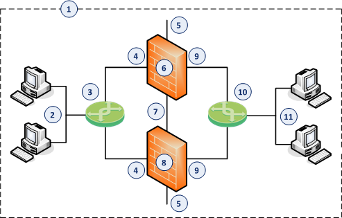
1
|
Network, which an administrator needs to divide into two Layer 2 segments.
The ClusterXL in Bridge Mode connects between these segments.
|
2
|
First network segment.
|
3
|
Switch that connects the first network segment to one bridged slave interface (4) on the ClusterXL in Bridge Mode.
|
4
|
One bridged slave interface (for example, eth1) on the Cluster Members in Bridge Mode.
|
5
|
Dedicated Gaia Management Interface (for example, eth0) on the Cluster Members.
|
6
|
First Cluster Member in Bridge Mode (in the Active cluster state).
|
7
|
Network that connects dedicated synchronization interfaces (for example, eth3) on the ClusterXL in Bridge Mode.
|
8
|
Second Cluster Member in Bridge Mode (in the Active cluster state).
|
9
|
Another bridged slave interface (for example, eth2) on the Cluster Members in Bridge Mode.
|
10
|
Switch that connects the second network segment to the other bridged slave interface (9) on the ClusterXL in Bridge Mode.
|
11
|
Second network segment.
|
Step
|
Description
|
1
|
In your web browser, connect to the Gaia Portal on the Security Gateway.
|
2
|
In the left navigation tree, click > .
|
3
|
Make sure that the slave interfaces, which you wish to add to the Bridge interface, do not have IP addresses.
|
4
|
Click > .
To configure an existing Bridge interface, select the Bridge interface and click .
|
5
|
On the tab, enter or select a ID (unique integer between 1 and 1024).
|
6
|
Select the interfaces from the list and then click .
Notes:
- A Bridge interface in Gaia can contain only two slave interfaces.
- Do not select the interface that you configured as Gaia Management Interface.
|
7
|
On the tab, do not enter the IPv4 address.
|
8
|
On the tab (optional), do not enter the IPv6 address.
|
9
|
Click .
|
Step 3 of 4: Configure the ClusterXL in High Availability mode in SmartConsole - Wizard Mode
Step
|
Description
|
1
|
Connect with SmartConsole to the Security Management Server or Domain Management Server that should manage this ClusterXL.
|
2
|
From the left navigation panel, click .
|
3
|
Create a new Cluster object in one of these ways:
- From the top toolbar, click the
 . . - In the top left corner, click menu .
- In the top right corner, click .
|
4
|
In the window, click .
|
5
|
On the page:
- In the field, enter the desired name for this ClusterXL object.
- Configure the main Virtual IP address(es) for this ClusterXL object.
In the section, enter the main Virtual IPv4 address for this ClusterXL object.
In the section, enter the main Virtual IPv6 address for this ClusterXL object.
- In the field, select and .
- Click .
|
6
|
On the page, add the objects for the Cluster Members.
- Click .
The window opens.
- In the field, enter the desired name for this Cluster Member object.
- Configure the main physical IP address(es) for this Cluster Member object.
In the and fields, configure the same IPv4 and IPv6 addresses that you configured on the page of the Cluster Member's First Time Configuration Wizard. Make sure the Security Management Server or Multi-Domain Server can connect to these IP addresses.
- In the and fields, enter the same Activation Key you entered during the Cluster Member's First Time Configuration Wizard.
- Click .
- Click .
- Repeat Steps a-f to add the second Cluster Member, and so on.
|
|
If the field does not show Established, perform these steps:
- Connect to the command line on the Cluster Member.
- Make sure there is a physical connectivity between the Cluster Member and the Management Server (for example, pings can pass).
- Run:
cpconfig - Enter the number of this option:
Secure Internal Communication. - Follow the instructions on the screen to change the Activation Key.
- In the SmartConsole, click .
- Enter the same Activation Key you entered in the
cpconfig menu. - Click .
|
7
|
On the page, configure the roles of the cluster interfaces:
- Examine the at the top of the page.
- Select the applicable role:
- For cluster traffic interfaces, select and configure the Cluster Virtual IPv4 address and its Net Mask.
- For cluster synchronization interfaces, select and select only. Check Point cluster supports only one synchronization network.
- For interfaces that do not pass the traffic between the connected networks, select .
- Click .
|
8
|
On the page:
- Examine the .
- Select .
- Click .
The window opens.
|
9
|
On the page > section:
- In the field, make sure you see the configured desired name for this ClusterXL object.
- In the and fields, make sure you see the configured IP addresses.
|
10
|
On the page > section, select the correct options:
- In the field:
If you install the Cluster Members on Check Point Appliances, select the correct appliances series.
If you install the Cluster Members on Open Servers, select .
- In the field, select .
- In the field, select .
|
11
|
On the page > tab:
- Make sure the Software Blade is selected.
- Enable the additional desired Software Blades.
Important:
- See the Supported Software Blades in Bridge Mode and Limitations in Bridge Mode.
- Do not select anything on the tab.
|
12
|
On the page:
- Click .
The window opens.
- In the field, enter the desired name for this Cluster Member object.
- Configure the main physical IP address(es) for this Cluster Member object.
In the and fields, configure the same IPv4 and IPv6 addresses that you configured on the page of the Cluster Member's First Time Configuration Wizard. Make sure the Security Management Server or Multi-Domain Server can connect to these IP addresses.
- Click .
- In the and fields, enter the same Activation Key you entered during the Cluster Member's First Time Configuration Wizard.
- Click .
- Click .
- Click .
- Repeat Steps a-h to add the second Cluster Member, and so on.
|
|
If the field does not show Established, perform these steps:
- Connect to the command line on the Cluster Member.
- Make sure there is a physical connectivity between the Cluster Member and the Management Server (for example, pings can pass).
- Run:
cpconfig - Enter the number of this option:
Secure Internal Communication. - Follow the instructions on the screen to change the Activation Key.
- In the SmartConsole, click .
- Enter the same Activation Key you entered in the
cpconfig menu. - Click .
|
13
|
On the page:
- In the section, select and .
- In the section, select the desired option.
- In the section:
- Optional: Select . We recommend to select this option.
- Optional: Select (for more information, see sk50840).
- Select the High Availability recovery - , or .
|
14
|
On the page:
- Select each interface and click . The window opens.
- From the left navigation tree, click the page.
- In the section, in the field, select the applicable type:
- For cluster traffic interfaces, select . Make sure the Cluster Virtual IPv4 address and its Net Mask are correct.
- For cluster synchronization interfaces, select or (we do not recommend this configuration). Check Point cluster supports only one synchronization network.
- For interfaces that do not pass the traffic between the connected networks, select .
- In the section, make sure the IPv4 address and its Net Mask are correct on each Cluster Member.
Note - For cluster traffic interfaces, you can configure the Cluster Virtual IP address to be on a different network than the physical IP addresses of the Cluster Members. In this case, you must configure the required static routes on the Cluster Members.
- In the section:
- Make sure the settings are correct in the and fields.
- Make sure to enable the .
Important:
- Make sure the Bridge interface and Bridge slave interfaces are not in the Topology.
- You cannot define the of the Bridge interface. It is by default.
|
15
|
Click .
|
16
|
Publish the SmartConsole session.
|
Step 3 of 4: Configure the ClusterXL in High Availability mode in SmartConsole - Classic Mode
Step
|
Description
|
1
|
Connect with SmartConsole to the Security Management Server or Domain Management Server that should manage this ClusterXL.
|
2
|
From the left navigation panel, click .
|
3
|
Create a new Cluster object in one of these ways:
- From the top toolbar, click the.
- In the top left corner, click menu .
- In the top right corner, click .
|
4
|
In the window, click .
The window opens.
|
5
|
On the page > section:
- In the field, enter the desired name for this ClusterXL object.
- In the and fields, configure the same IPv4 and IPv6 addresses that you configured on the page of the Cluster Member's First Time Configuration Wizard. Make sure the Security Management Server or Multi-Domain Server can connect to these IP addresses.
|
6
|
On the page > section, select the correct options:
- In the field:
If you install the Cluster Members on Check Point Appliances, select the correct appliances series.
If you install the Cluster Members on Open Servers, select .
- In the field, select .
- In the field, select .
|
7
|
On the page > tab:
- Make sure the Software Blade is selected.
- Enable the additional desired Software Blades.
Important:
- See the Supported Software Blades in Bridge Mode and Limitations in Bridge Mode.
- Do not select anything on the tab.
|
8
|
On the page:
- Click .
The window opens.
- In the field, enter the desired name for this Cluster Member object.
- Configure the main physical IP address(es) for this Cluster Member object.
In the and fields, configure the same IPv4 and IPv6 addresses that you configured on the page of the Cluster Member's First Time Configuration Wizard. Make sure the Security Management Server or Multi-Domain Server can connect to these IP addresses.
- Click .
- In the and fields, enter the same Activation Key you entered during the Cluster Member's First Time Configuration Wizard.
- Click .
- Click .
- Click .
- Repeat Steps a-h to add the second Cluster Member, and so on.
|
|
If the field does not show Established, perform these steps:
- Connect to the command line on the Cluster Member.
- Make sure there is a physical connectivity between the Cluster Member and the Management Server (for example, pings can pass).
- Run:
cpconfig - Enter the number of this option:
Secure Internal Communication. - Follow the instructions on the screen to change the Activation Key.
- In the SmartConsole, click .
- Enter the same Activation Key you entered in the
cpconfig menu. - Click .
|
9
|
On the page:
- In the section, select and .
- In the section, select the desired option.
- In the section:
- Optional: Select . We recommend to select this option.
- Optional: Select (for more information, see sk50840).
- Select the High Availability recovery - , or .
|
10
|
On the page:
- Select each interface and click . The window opens.
- From the left navigation tree, click the page.
- In the section, in the field, select the applicable type:
- For cluster traffic interfaces, select . Make sure the Cluster Virtual IPv4 address and its Net Mask are correct.
- For cluster synchronization interfaces, select or (we do not recommend this configuration). Check Point cluster supports only one synchronization network.
- For interfaces that do not pass the traffic between the connected networks, select .
- In the section, make sure the IPv4 address and its Net Mask are correct on each Cluster Member.
Note - For cluster traffic interfaces, you can configure the Cluster Virtual IP address to be on a different network than the physical IP addresses of the Cluster Members. In this case, you must configure the required static routes on the Cluster Members.
- In the section:
- Make sure the settings are correct in the and fields.
- Make sure to enable the .
Important:
- Make sure the Bridge interface and Bridge slave interfaces are not in the Topology.
- You cannot define the of the Bridge interface. It is by default.
|
11
|
Click .
|
12
|
Publish the SmartConsole session.
|
Step
|
Description
|
1
|
Connect with SmartConsole to the Security Management Server or Domain Management Server that manages this ClusterXL.
|
2
|
From the left navigation panel, click .
|
3
|
Create a new policy and configure the applicable layers:
- At the top, click the tab (or press ).
- On the tab, click .
- In the window, create a new policy and configure the applicable layers.
- Click .
- On the tab, click the new policy you created.
|
4
|
Create the applicable Access Control rules.
Important - See the Supported Software Blades in Bridge Mode and Limitations in Bridge Mode.
|
5
|
Install the Access Control Policy on the ClusterXL Cluster object.
|
6
|
Examine the cluster configuration:
- Connect to the command line on each Cluster Member.
- Run:
In Gaia Clish:
show cluster state
In Expert mode:
cphaprob state
Example output:
Cluster Mode: High Availability (Active Up, Bridge Mode) with IGMP Membership
Number Unique Address Firewall State (*)
1 (local) 2.2.2.3 Active
2 2.2.2.2 Active
|