


|
|
|
When you define a Bridge interface on a Cluster Member, Bridge Active/Active mode is enabled by default.
Notes:
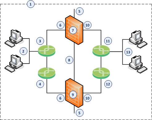
Example:
Item |
Description |
|---|---|
1 |
Network, which an administrator needs to divide into two Layer 2 segments. The ClusterXL in Bridge Mode connects between these segments. |
2 |
First network segment. |
3 |
Switch that connects the first network segment to one bridged slave interface (6) on the ClusterXL in Bridge Mode. |
4 |
Switch that connects between one switch (that directly connects to the first network segment) and one bridged slave interface (6) on the ClusterXL in Bridge Mode. |
5 |
Dedicated Gaia Management Interface (for example, |
6 |
One bridged slave interface (for example, |
7 |
First Cluster Member in Bridge Mode (in the |
8 |
Network that connects dedicated synchronization interfaces (for example, |
9 |
Second Cluster Member in Bridge Mode (in the |
10 |
Another bridged slave interface (for example, |
11 |
Switch that connects the second network segment to the other bridged slave interface (10) on the ClusterXL in Bridge Mode. |
12 |
Switch that connects between one switch (that directly connects to the second network segment) and the other bridged slave interface (10) on the ClusterXL in Bridge Mode. |
13 |
Second network segment. |
Workflow:
The workflow and detailed instructions are the same as in the Configuring ClusterXL in Bridge Mode - Active/Active with Two Switches.

