

In This Section: |
Domain Based VPN controls how VPN traffic is routed between Security Gateways within a community. To route traffic to a host behind a Security Gateway, you must first define the VPN domain for that Security Gateway. Configuration for VPN routing is done with SmartConsole or in the VPN routing configuration files on the Security Gateways.
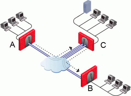
In this figure, one of the host machines behind Security Gateway A tries to connect to a host computer behind Security Gateway B. For technical or policy reasons, Security Gateway A cannot establish a VPN tunnel with Security Gateway B. With VPN Routing, Security Gateways A and B can establish VPN tunnels through Security Gateway C.

Item |
Description |
|---|---|
A |
Security Gateway A |
B |
Security Gateway B |
C |
Security Gateway C |
VPN routing connections are subject to the same access control rules as any other connection. If VPN routing is correctly configured but a Security Policy rule exists that does not allow the connection, the connection is dropped. For example: a Security Gateway has a rule which forbids all FTP traffic from inside the internal network to anywhere outside. When a peer Security Gateway opens an FTP connection with this Security Gateway, the connection is dropped.
For VPN routing to succeed, a single rule in the Security Policy Rule Base must cover traffic in both directions, inbound and outbound, and on the central Security Gateway. To configure this rule, see Configuring the 'Accept VPN Traffic Rule.
Configure most common VPN routing scenarios through a VPN star community in SmartConsole.
You can also configure VPN routing between Security Gateways in the Security Management Server configuration file $FWDIR/conf/vpn_route.conf.
You can only configure VPN routing between Security Gateways that belong to a VPN community.
To configure a VPN Routing in a star community in SmartConsole:
For more granular control over VPN routing, edit the $FWDIR/conf/vpn_route.conf file on the Security Management Server.
The configuration file, $FWDIR/conf/vpn_route.conf, is a text file that contains the name of network objects.
The format is: Destination, Next hop, Install on Security Gateway (with tabbed spaces separating the elements).
Consider a simple VPN routing scenario consisting of Center gateway (hub) and two Satellite gateways (spokes). All machines are controlled from the same Security Management Server, and all the Security Gateways are members of the same VPN community. Only Telnet and FTP services are to be encrypted between the Satellites and routed through the Center:
Although you can do this easily in a VPN Star community, you can achieve the same goal if you edit the $FWDIR/conf/vpn_route.conf file:
Destination |
Next hop router interface |
Install on |
|---|---|---|
Spoke_B_VPN_Dom |
Hub_C |
Spoke_A |
Spoke_A_VPN_Dom |
Hub_C |
Spoke_B |
In this instance, Spoke_B_VPN_Dom is the name of the network object group that contains spoke B's VPN domain. Hub C is the name of the Security Gateway enabled for VPN routing. Spoke_A_VPN_Dom is the name of the network object that represents Spoke A's encryption domain.
Example of the file contents:
Spoke_B_VPN_DOM Hub_C Spoke_A Spoke_A_VPN_DOM Hub_C Spoke_B |
In SmartConsole:
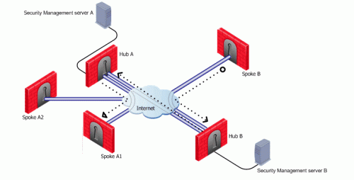
Consider two Hubs, A and B. Hub A has two spokes, spoke_A1, and spoke_A2. Hub B has a single spoke, spoke_B. In addition, Hub A is managed from Security Management Server A, while Hub B is managed via Security Management Server B:

For the two VPN star communities, based around Hubs A and B:
A_community is the VPN community of A plus the spokes belonging to A. B_community is the VPN community. Hubs_community is the VPN community of Hub_A and Hub_B.
The $FWDIR/conf/vpn_route.conf file on Security Management Server 1 looks like this:
Destination |
Next hop router interface |
Install on |
|---|---|---|
Spoke_B_VPN_Dom |
Hub_A |
A_Spokes |
Spoke_A1_VPN_Dom |
Hub_A |
Spoke_A2 |
Spoke_A2_VPN_Dom |
Hub_A |
Spoke _A1 |
Spoke_B_VPN_Dom |
Hub_B |
Hub_A |
Spokes A1 and A2 are combined into the network group object "A_spokes".
The applicable rule in the Security Policy Rule Base looks like this:
Source |
Destination |
VPN |
Service |
Action |
|---|---|---|---|---|
*Any |
*Any |
A_Community B_Community Hubs_Community |
*Any |
Accept |
The $FWDIR/conf/vpn_route.conf file on Security Management Server 2 looks like this:
Destination |
Next hop router interface |
Install On |
|---|---|---|
Spoke_A1_VPN_Dom |
Hub_B |
Spoke_B |
Spoke_A2_VPN_Dom |
Hub_B |
Spoke_B |
Spoke_A1_VPN_Dom |
Hub_A |
Hub_B |
Spoke_A2_VPN_Dom |
Hub_A |
Hub_B |
The applicable rule in the Security Policy Rule Base looks like this:
Source |
Destination |
VPN |
Service |
Action |
|---|---|---|---|---|
*Any |
*Any |
B_Community A_Community Hubs_Community |
*Any |
Accept |
For both $FWDIR/conf/vpn_route.conf files:

You can configure a VPN star community between two SmartLSM Profiles. The procedures below show a SmartLSM Gateway Profile and SmartLSM Cluster Profile. You can also configure the community with two SmartLSM Cluster Profiles or two SmartLSM Gateway Profiles. All included SmartLSM Gateways and Cluster Profiles must have the IPsec VPN blade enabled.
The procedure requires configuration in: