


|
|
|
In This Section: |
There are a number of scenarios in which a Security Gateway or remote access clients cannot connect directly to another Security Gateway (or clients). Sometimes, a given Security Gateway or client is incapable of supplying the required level of security. For example:
In all cases, a method is needed to enhance connectivity and security.
VPN routing provides a way of controlling how VPN traffic is directed. VPN routing can be implemented with Security Gateway modules and remote access clients. Configuration for VPN routing is performed either directly through SmartConsole (in simple cases) or by editing the VPN routing configuration files on the Security Gateways (in more complex scenarios).
Item |
Description |
|---|---|
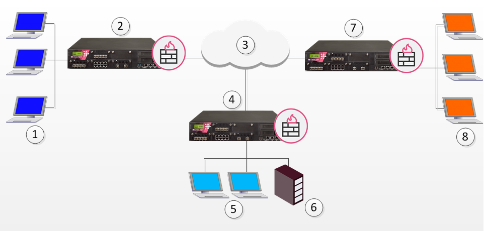
1 |
Host machines |
2 |
Security Gateway A |
3 |
Internet |
4 |
Security Gateway B |
5 |
Host machines |
6 |
Security Management Server |
7 |
Security Gateway C |
8 |
Host machines |
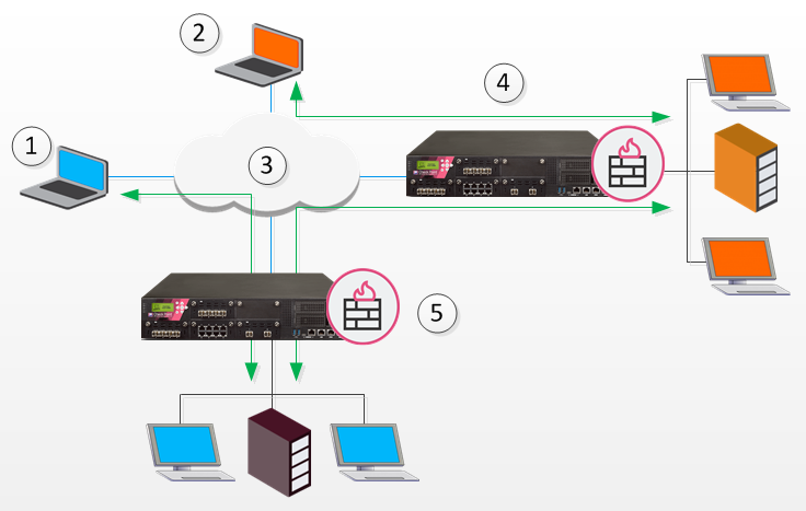
In the figure above, one of the host machines behind Security Gateway A needs to connect with a host machine behind Security Gateway B. For either technical or policy reasons, Security Gateway A cannot open a VPN tunnel with Security Gateway B. However, both Security Gateways A and B can open VPN tunnels with Security Gateway C, so the connection is routed through Security Gateway C.
As well as providing enhanced connectivity and security, VPN routing can ease network management by hiding a complex network of Security Gateways behind a single Hub.
VPN routing for remote access clients is enabled via Hub Mode. In Hub mode, all traffic is directed through a central Hub. The central Hub acts as a kind of router for the remote client. Once traffic from remote access clients is directed through a Hub, connectivity with other clients is possible as well as the ability to inspect the subsequent traffic for content.
When using Hub mode, enable Office mode. If the remote client is using an IP address supplied by an ISP, this address might not be fully routable. When Office mode is used, rules can be created that relate directly to Office mode connections.
Note - Office mode is not supported in SecuRemote.
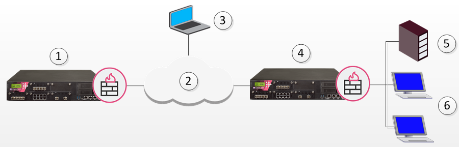
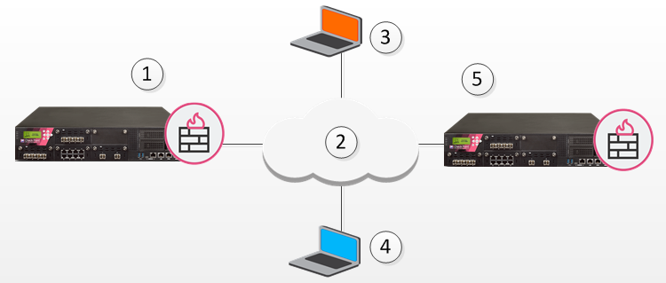
In the following figure, the remote client needs to connect with a server behind Security Gateway 2. Company policy states that all connections to this server must be inspected for content. For whatever reason, Security Gateway 2 cannot perform the required content inspection. When all the traffic is routed through Security Gateway 1, connections between the remote client and the server can be inspected.
Item |
Description |
|---|---|
1 |
Security Gateway 1 |
2 |
Internet |
3 |
Remote client |
4 |
Security Gateway 2 |
5 |
Server |
6 |
Hosts |
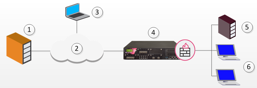
Suppose the same remote client needs to access an HTTP server on the Internet. The same company policy regarding security still applies.
Item |
Description |
|---|---|
1 |
HTTP Server |
2 |
Internet |
3 |
Remote client |
4 |
Security Gateway |
5 |
OSPEC Certified UFP server |
6 |
Hosts |
The remote client's traffic is directed to the Security Gateway where it is directed to the UFP (URL Filtering Protocol) server to check the validity of the URL and packet content, since the Security Gateway does not possess URL-checking functionality. The packets are then forwarded to the HTTP server on the Internet.
NATing the address of the remote client behind the Security Gateway prevents the HTTP server on the Internet from replying directly to the client. If the remote client's address is not NATed, the remote client will not accept the clear reply from the HTTP server.
Remote client to client connectivity is achieved in two ways:
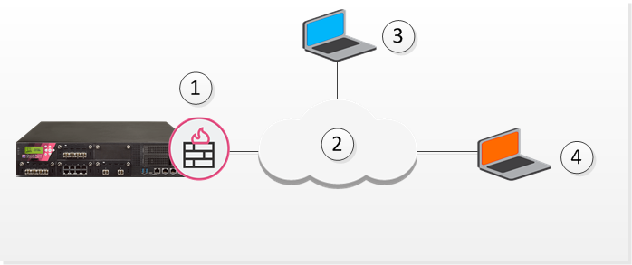
Two remote users use VoIP software to hold a secure conversation. The traffic between them is directed through a central Hub, as shown in the following figure.
Item |
Description |
|---|---|
1 |
Security Gateway |
2 |
Internet |
3 |
Remote Client VoIP |
4 |
Remote Client VoIP |
For this to work:
If the two remote clients are configured for Hub mode with different Security Gateways, the routing takes place in three stages - each remote client to its designated Security Gateway, then between the Security Gateways:
Item |
Description |
|---|---|
1 |
Remote Client 1 |
2 |
Remote Client 2 |
3 |
Internet |
4 |
Security Gateway A |
5 |
Security Gateway B |
In the figure above, remote client 1 is configured for Hub mode with Security Gateway B. Remote client 2 is configured for Hub mode with Security Gateway A. For the connection to be routed correctly:
Common VPN routing scenarios can be configured through a VPN star community, but not all VPN routing configuration is handled through SmartConsole. VPN routing between Security Gateways (star or mesh) can be also be configured by editing the configuration file $FWDIR/conf/vpn_route.conf
VPN routing cannot be configured between Security Gateways that do not belong to a VPN community.
To enable Hub Mode for Remote Access clients:
The gateway window opens and shows the General Properties page.
VPN routing traffic is handled in the Security Policy Rule Base as a single connection, matched to one rule only.
SmartConsole includes a default object for Office Mode IP addresses, CP_default_Office_Mode_addresses_pool. You can use the default object, or create a new one for your network.
To create a new Office Mode IP address object:
To configure VPN routing for remote access clients with the VPN domain:
The gateway window opens and shows the General Properties page.
The remote clients must connect to the site and perform a site update before they can communicate with each other.
The figure below shows two remote clients each configured to work in Hub mode with a different Security Gateway:
Item |
Description |
|---|---|
1 |
Hub 1 |
2 |
Internet |
3 |
Remote Client 1 |
4 |
Remote Client 2 |
5 |
Hub 2 |
Remote Client 1 works in Hub mode with Hub 1. Remote Client 2 works in Hub mode with the Hub 2. In order for VPN routing to be performed correctly:
Destination |
Next hop router interface |
Install On |
|---|---|---|
Hub1_OfficeMode_range |
Hub1 |
Hub2 |
Hub2_OfficeMode_range |
Hub2 |
Hub1 |
When Remote Client 1 communicates with Remote Client 2:
Link Selection is a method used to determine which interface to use for incoming and outgoing VPN traffic and the best possible path for the traffic. Using Link Selection, you choose which IP addresses are used for VPN traffic on each Security Gateway.
Load Sharing and Service Based Link Selection are not supported when the peer is a Remote Access Client. If the Probing Redundancy mode configuration is Load Sharing and the peer is a remote access client, High Availability will be enforced for the client's tunnel.
Link selection is configured on each Security Gateway in the Security Gateway Properties > IPSec VPN > Link Selection window. The settings apply to both:
You can configure Link Selection for remote users separately. These settings override the settings configured on the Link Selection page.
To configure separate Link Selection settings for remote access VPN:
apply_resolving_mechanism_to_SR to false.ip_resolution_mechanism attribute to determine how remote access clients resolve the IP address of the local Security Gateway. Add one of the following: mainIpVpn - Always use the main IP address specified in the IP Address field on the General Properties page of the Security GatewaysingleIpVpn - The VPN tunnel is created with the Security Gateway using an IP address set in single_VPN_IP_RAsingleNATIpVPN - The VPN tunnel is created using a NATed IP address set in single_VPN_IP_RAtopologyCalc - Calculate the IP address used for the VPN tunnel by network topology based on the location of the remote peeroneTimeProb - Use one time probing to determine which link will be used.ongoingProb - Use ongoing probing to determine which link will be used.interface_resolving_ha_primary_if – The primary IP address used for one-time / ongoing probing.use_interface_IP – Set to true if all IP addresses defined in topology tab should be probed. Set to false if the manual list of IP addresses should be probed.available_VPN_IP_list - A List of IP addresses that should be probed. (This list is used only if the value of use_interface_IP is false).To use multiple external links with remote access clients:
The gateway window opens and shows the General Properties page.
Directional VPN for Remote Access Communities lets you reject connections to or from a specified network object.
Source |
Destination |
VPN |
Service |
Action |
|---|---|---|---|---|
Any |
Any |
Remote_Access_Community => MyIntranet |
Any |
drop |
Any |
Any |
Remote_Access_Community => Any Traffic |
Any |
accept |
Connections are not allowed between remote users and hosts within the "MyIntranet" VPN community. All other connections that start from the Remote Access Community, from inside or outside of the VPN communities, are allowed.
User groups can be placed in the destination column of a rule. This makes:
Source |
Destination |
VPN |
Service |
Action |
|---|---|---|---|---|
Any |
Remote_Users@Any |
Any Traffic => Remote_Access_Community |
Any |
accept |
To include user groups in the destination column of a rule:
To configure Directional VPN with Remote Access communities:
The New Directional Match Condition window opens.

