


|
|
|
In This Section: |
ACI supports physical and virtual L4-L7 devices.
For physical devices, use Check Point appliances. For more information and to verify appliance compatibility, see the R80.10 CloudGuard for ACI Release Notes.
For virtual devices, use Check Point CloudGuard VE for VMware. For more information, see sk104859.
In the CloudGuard for ACI model, the L4-L7 devices are mapped to Security Gateways that serve as concrete devices. Check Point supports VSX and non-VSX Security Gateways.
When you do the service insertion, the Cisco APIC server supports and provisions Virtual Systems or Security Gateways. See Basic Service Insertion Overview.
To deploy CloudGuard Gateway for virtual devices:
These ports are allowed by intermediate devices which inspect the management connections. For more information, see sk52421.
For PBR deployments, ClusterXL VMAC mode is required. See sk50840 for configuration details.
For cluster deployment only:
The ClusterXL ARP forwarding mechanism must be disabled.
$FWDIR/modules/fwkern.conf file: fwha_enable_arp_resend=0
If the configuration file does not exist on the machine, you must create it. Reboot is required.
Important - Policy installation is required. Make sure to enable cprid service (port:tcp/18208).
To deploy the CloudGuard Gateway for physical devices:
These ports are allowed by intermediate devices which inspect the management connections. For more information, see sk52421.
For cluster deployment only:
The ClusterXL ARP forwarding mechanism must be disabled.
$FWDIR/modules/fwkern.conf file: fwha_enable_arp_resend=0
If the configuration file does not exist on the machine, you must create it. Reboot is required.
Important - Policy installation is required. Make sure to enable cprid service (TCP port 18208).
For PBR deployments, ClusterXL VMAC mode is required. See sk50840 for configuration details.
Install the CloudGuard Controller Enforcer Hotfix on R77.30 Security Gateways with CPUSE, online or offline.
To install the Hotfix on R77.30 Security Gateways with CPUSE online:
Select the CloudGuard Controller Enforcer Hotfix package.
The online installation starts immediately. The gateway reboots when installation is complete.
To install the Hotfix on R77.30 Security Gateways with CPUSE offline:
See Section 3 to find the latest CPUSE build, and Section 4-A to download and import a CPUSE package.
The Import Package window opens.
Select the imported package.
The offline installation starts immediately. The gateway reboots when installation is complete.
CloudGuard for ACI solution supports L2 (GoThrough, transparent), and L3 (GoTo, routed) service function modes.
Before you start the deployment, we recommend that you designate the application profiles, network paths, and contracts that require security service, and determine the optimal insertion method. These considerations are specified in the CloudGuard for ACI TDM document.
ACI deployment topology example:
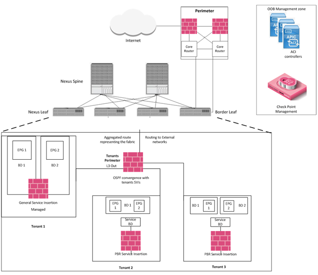
Best practice - Use the steps below to insert a service installation into the ACI fabric.
The APIC service insertion process uses the policy package as the Security Policy Name parameter.
You must install the CloudGuard device package on Cisco APICs to enable the insertion of managed L4-L7 Check Point devices. The CloudGuard device package is compatible with APIC versions 1.2 and higher.
You can manually upload the CloudGuard device package into the Cisco APIC. See the Cisco Administration Guide, Installing Device Packages. You can do this automatically with the vsec_config utility.
To configure a device package username:
vsec_config utility > Cisco ACI configuration > APIC L4-L7 Device User > Set Username.Note - The username is the R80.10 admin name that the user wants to use for ACI provisioning actions. The user must set a read/write profile to assign use permissions.
To automatically upload a device package:
To upload the device package directly from the Check Point Security Management Server, verify that the credentials used to integrate the CloudGuard Controller with Cisco APIC allow device package uploads.
To learn more, see the CloudGuard Controller R80.10 Administration Guide.
vsec_config utility > Cisco ACI configuration > Install device package.If more than one Cisco APIC Data Center object exists, select the Data Center server which represents the specified Cisco APIC server.
In a Multi-Domain deployment, use the domain context to upload the package.
Note - For Multi-Domain Server High Availability, execute the command in a Multi-Domain context.
When you configure a new device, it must be part of a domain that assigns dynamic VLANs.
Note - When you change the password for a device, the password for the concrete device under the main device does not change automatically.
To add an L4-L7 device:
Property |
Action |
General |
|
Managed |
Make sure this option is selected. |
Name |
Use the exact VSX/Gateway object name which you created in SmartConsole. |
Service Type |
Select Firewall. |
Device Type |
Select Physical for a Check Point appliance or Virtual for CloudGuard VE. |
Domain |
Select the physical or VMM domain where the VSX/ Gateway is deployed. |
Mode |
Select Single node for a single VSX/Gateway. Select HA cluster for a VSX cluster/Gateway cluster based solution. |
Device Package |
Select Gateway Device Package from the drop down list. |
Model |
Select the relevant model for all Check Point appliances:
|
Function Type |
Select GoTo for routed (L3) Mode use case, including PBR. Select GoThrough for transparent (L2) mode use case. |
Connectivity |
|
APIC to Device Management Connectivity |
Configure based on environment design. Best practice -Use Out Of Band connectivity for management connections. |
Credentials |
|
Username |
Enter the username provided in the |
Password |
Enter the user password. |
Device 1 (and Device 2 when a High Availability cluster is selected) |
|
Management IP address |
Enter the IP address of the Check Point Security Management Server. For Management High Availability, use the primary server IP address. Note - Devices are managed through IPv4. IPv6 is not supported for management connectivity to the device. |
Management Port |
Select https. |
VM (Relevant to virtual device types only). |
Select the CloudGuard VE VM used to inspect the traffic. |
Chassis |
(Leave blank) |
Device Interfaces |
Physical domain:
Virtual domain:
Note - Mapping of the Name and vNIC must be verified on the CloudGuard VE VM. For example, there is no guarantee that |
Cluster |
|
Management IP address |
Enter the Check Point Security Management Server IP address. For Management High Availability, use the primary server IP address. |
Management Port |
Select https. |
Device Manager |
For Management High Availability, select the device manager you configured. For more information, see Configuring Management HA Integration. For others, leave blank. |
Cluster Interfaces |
Physical device:
Virtual device:
|
A service BD is a bridge domain that the L4-L7 device connects to (either the Check Point VSX or Security Gateway).
To create an L4-L7 Service Graph template:
Property |
Action |
|---|---|
Graph Name |
Enter the graph name. |
Graph Type |
Select a graph creation option:
If you select Clone An Existing One enter the graph template. |
Type |
Select the graph type based on the design considerations:
|
Profile |
Select the default profile based on the graph type you choose:
|
To configure PBR policy with the APIC GUI:
Use this policy when you apply the L4-L7 service graph template.
Note - For N9K-93128TX, N9K-9396PX, N9K-9396TX, N9K-9372PX, and N9K-9372TX switches, the service appliance must not be in the same leaf switch as the source or destination endpoint group.
For N9K-C93180YC-EX and N9K-93108TC-EX switches, the service appliance can be in the same leaf switch as the source or destination endpoint group.
You can apply a service graph that describes a Check Point L4-L7 device insertion. A Virtual System is created automatically or an existing Virtual System is added with interfaces and routes based on configured parameters.
For a directly connected (general) insertion, any new interface that you configure for the device is automatically added to the Virtual System. An interface that you configure connects it to the bridge domain that contains the EPG.
Notes:
Directly connected (L2 adjacency) insertion requires that you enable ARP Flooding on the bridge domains connected to the L4-L7 device.
When you use a virtual device in a cluster configuration with VMAC enabled, make sure that Promiscuous Mode is enabled on the shadow port group. It is created by the APIC after the service graph is applied.
To apply the service graph to a contract:
EPGs and Contract Information
Property |
Action |
|
|---|---|---|
EPGs Information |
||
Consumer EPG/External Network |
Select the consumer EPG name or the external network name. |
|
Provider EPG/External Network |
Select the provider EPG name or external network name. |
|
Contract Information |
||
Contract |
Select a contract option:
|
|
Contract Name (For a new contract only). |
Enter the contract name. |
|
No Filter (For a new contract only). |
If No Filter is checked, the contract applies to all traffic types and security is enforced only based on the Check Point security policy installed on the device. If No Filter is unchecked, the Filter Entries table opens and shows the ACI filters you can add before Check Point inspection. Note - For PBR, a contract must have filters that only match IP traffic. |
|
Existing Contracts with Subject |
The contract subject name. |
|
Consumer, Provider and Route Configurations
Property |
Action |
|---|---|
Graph Template |
Verify the graph template name. |
Consumer Connector |
General – Use this to configure a directly connected service insertion, L2 adjacency or PBR. In this mode, the routed or transparent service interface is connected directly to the BD you choose. For PBR it is a service BD and for L2 adjacency, it is an endpoint BD. In General Mode, configure the BD that is connected to the device on the consumer interface, and select Cluster Interface consumer. Virtual Deployment - Select the corresponding interface name. Route Peering – Use Route Peering to configure route peering, L3 out, and service insertion. In this mode, the device learns networks through static or dynamic routing, and traffic is steered to the device through the external L3 network. In Route Peering Mode, configure the L3 external network connected to the device on the consumer interface. Select Cluster Interface consumer. Redirect Policy (for PBR only) - Select the PBR redirect policy you created. |
Provider Connector |
General –Use this to configure a directly connected service insertion, L2 adjacency or PBR. In this mode, the routed or transparent service interface is connected directly to the BD you choose. For PBR it is a service BD and for L2 adjacency, it is an endpoint BD. In General mode, configure the BD connected to the device on the provider interface and select Cluster Interface provider. Virtual Deployment - Select the corresponding interface name. Route Peering – Use Route Peering to configure route peering, L3 out, and service insertion. In this mode, the device learns networks through static or dynamic routing and traffic is steered to the device through the external L3 network. In Route Peering mode, configure the L3 external network connected to the device on the provider interface. Select Cluster Interface provider. Redirect Policy (for PBR only) - Select the PBR redirect policy you created. |
Routing Config (Route Peering only). |
Select:
|
Device Parameters
Parameter |
Function |
|---|---|
IPv4 Consumer Facing Address IPv4 Provider Facing Address |
Configures the network interfaces, IPv4 address, and prefix for the consumer and provider interfaces. Use this format:
|
IPv6 Consumer Facing Address IPv6 Provider Facing Address |
Configures the network interfaces, IPv6 address, and prefix for the consumer and provider interfaces. You can write the IPv6 address in its abbreviated form. For example, 20a1:0db8::0001/112 Note - A prerequisite for using an IPv6 address is enabling IPv6 support on the relevant Virtual System or Security Gateway. See sk39374. |
Instance Name |
Use this for instantiation of a new Virtual System on the VSX gateway. If an instance that runs the required policy already exists on the device, the existing instance is modified and a new instance is not created. To create a new instance, assign it a specific name. |
Security Domain |
Required for Multi-Domain Server deployment. The default is no MDM. Specifies the domain server name that contains the device. |
Security Policy Name |
Determines the policy package that is installed on the security instance. The policy package must exist on the Security Management Server. |
Route Entry |
Static routes are added to the VS routing table. Multiple routing entries may be added. Static route entries include:
Note - To set a default static route, use 0.0.0.0/0 in the Destination Address field. |
Device Parameters for PBR
Parameter |
Function |
|---|---|
Firewall Interface Address |
Configures the IP address (CIDR notation) for the firewall interface. Put it in the same subnet you define on the service BD.
|
Instance Name |
Use this for instantiation of a new Virtual System on the VSX gateway. If an instance that runs the required policy already exists on the device, the existing instance is modified and a new instance is not created. To create a new instance, assign it a specific name. |
Security Domain |
Required for Multi-Domain Server deployment. The default is no MDM. Specifies the domain server name that contains the device. |
Security Policy Name |
Determines the policy package that is installed on the security instance. The policy package must exist on the Security Management Server. |
Service-BD Gateway Address |
IP address of the gateway defined for the service BD. |
To configure Management High Availability integration, you must create a Device Manager:
vsec_config command and are the same as the ones used in Adding an L4-L7 Device.Note - Only Management High Availability with two devices is supported.
Note - The Management IP address defined in Adding an L4-L7 Device is treated as the primary management.
The Cisco ACI solution is VSX based. You can select the domain that holds and manages the Virtual Systems. You must configure the domain in the Service Parameters to integrate the solution with the Check Point Multi-Domain Server.
To configure the domain in the Service Parameters:
Note - The domain name is part of the Virtual System object name that is provisioned by APIC.
Before you remove a tenant, we recommend that you remove all service graphs from the contracts. APIC removes tenants by best effort, which can leave configuration and constructs (such as service graphs) in the tenant that you would have removed.
When you remove a service graph used to insert a Check Point device, interfaces and routes configured by APIC on the inserted Virtual System are also removed. When you remove all service graphs attachments that render a specific Virtual System, that Virtual System is also removed entirely, including from the Security Management Server.
To remove Service Insertion:
To remove L4-L7 managed devices:
Note - Make sure that there are no entries that are related to the L4-L7 device you want to remove in the Deployed Devices section and in the Deployed Graph Instances sections.

