


|
|
|
This section explains configurations and procedures for Virtual Systems in Bridge mode. With native layer-2 bridging instead of IP routing, you can add Virtual Systems without affecting the existing IP structure.
When in Bridge mode, Virtual System interfaces do not require IP addresses. You can assign an IP address to the Virtual System itself (not the interfaces) to enable layer-3 monitoring. This feature enhances network fault detection.
VSX supports these Bridge mode models:
This section presents the procedures for enabling and configuring the STP Bridge mode for Virtual Systems and VSX Gateways.
The same procedures are applicable for a VSX Cluster for PVST + Load Sharing.
Define and configure the Spanning Tree structure according to your network requirements. (For PVST + Load Sharing, configure the structure for each VLAN.)
See your hardware documentation for the specific procedures for your network deployment.
cpconfigTo enable the Active/Active Bridge mode for a cluster:
The VSX Cluster Properties window opens.
To configure a Virtual System to use bridge mode, define it as a Virtual System in bridge mode when you first create it. You cannot reconfigure a non-Bridge mode Virtual System to use bridge mode later.
Define and configure the Spanning Tree structure for each VLAN according to your network deployment. Please refer to your network hardware documentation for specific procedures.
To configure a VSX Cluster for PVST + Load Sharing, perform the procedures described in the STP Bridge Mode section.
This section presents the procedures for enabling and configuring the Active/Standby Bridge Mode for Virtual Systems and VSX Gateways.
cpconfigEnter y and continue with the gateway configuration.
cpconfigTo enable the Active/Standby Bridge Mode for a cluster:
The VSX Cluster Properties window opens.
The Active/Standby Bridge Mode loop detection algorithms in ClusterXL are enabled.
To configure a Virtual System in Bridge Mode, define it as such when you first create the Virtual System object.
To configure a Virtual System for the Active/Standby Bridge Mode:
The Virtual System Network Configuration window opens.
The IP address must be unique and on the same subnet as the protected network.
This feature is supported only in R77.30 and higher, for VSX Gateways, and VSX Clusters in Active/Active Bridge mode.
Multi Bridge allows traffic from many different VLANs to move through one Virtual System in Bridge mode. In a Virtual System in Bridge mode, you can add physical and VLAN interfaces. When you add more than two VLAN interfaces, Multi Bridge is automatically enabled. Configure the same VLAN tag on each set of two interfaces to make them bridged.
Requirements for Multi Bridge interfaces:
For example, you define eth1.10, eth2.10, eth1.20, eth2.20. Now the VLAN Trunks, eth1 and eth2, cannot be used with other VLAN Trunks on other Virtual Systems in Bridge mode: eth1.30 cannot bridge with eth3.30.
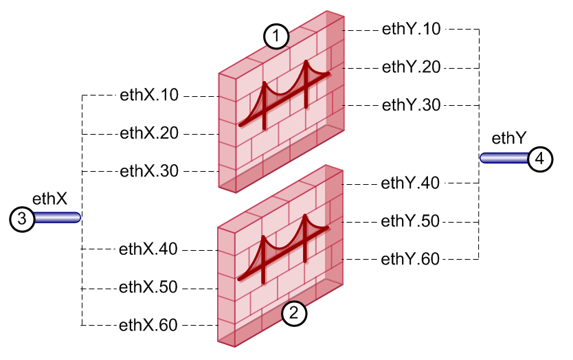
Item |
Description |
|---|---|
1 |
Virtual System in Bridge Mode with two bridges on VLAN interfaces with tags 81 and 82. |
2 |
Virtual System in Bridge Mode with three bridges on VLAN interfaces with tags 40, 50, and 60. |
3 |
VLAN Trunks. Each must be paired with the other in all bridges, or used without bridging. They cannot be paired with a different VLAN Trunk. |
To define a new Multi Bridge:
Make sure the interfaces in each pair have the same VLAN tag, from different interfaces.
For example:
eth2.50, eth2.51
eth3.50, eth3.51
Make sure to use the same two VLAN Trunks.
To convert a Bridge to a Multi Bridge:

