


|
|
|
In This Section: |
These are features that you can enable to increase the performance of the Firewall:
These Gateway clustering solutions enable you to enhance network redundancy:
These are software based features that are included in the Check Point operating systems. It is not necessary to purchase additional hardware to use them.
In a Security Gateway with CoreXL enabled, the Firewall kernel is replicated multiple times. Each replicated instance runs on one processing core. These instances handle traffic concurrently and each instance is a complete Firewall kernel that inspects traffic. When CoreXL is enabled, all Firewall instances in the Security Gateway process traffic through the same interfaces and apply the same gateway security policy.
When you enable CoreXL, the number of kernel instances is based on the total number of CPU cores.
Number of Cores |
Number of Kernel Instances |
|---|---|
1 |
1 |
2 |
2 |
4 |
3 |
6-20 |
Number of cores, minus 2 |
More than 20 |
Number of cores, minus 4. Up to a total of 40 instances. Cores can be IPv4 or IPv6. |
Use the cpconfig
To enable/disable CoreXL:
cpconfigConfigure Check Point CoreXLTo configure the number of instances:
cpconfigConfigure Check Point CoreXLIf CoreXL is disabled, enable CoreXL and then set the number of CoreXL firewall instances.
To learn more about CoreXL, see the R80.10 Performance Tuning Administration Guide
SecureXL is an acceleration solution that maximizes performance of the Firewall and does not compromise security. When SecureXL is enabled on a Security Gateway, some CPU intensive operations are processed by virtualized software instead of the Firewall kernel. The Firewall can inspect and process connections more efficiently and accelerate throughput and connection rates. These are the SecureXL traffic flows:
The goal of a SecureXL configuration is to minimize the connections that are processed on the slow path.
Throughput Acceleration
Connections are identified by the 5 tuple attributes: source address, destination address, source port, destination port, protocol. When the packets in a connection match all the 5 tuple attributes, the traffic flow can be processed on the accelerated path.
The first packets of a new TCP connection require more processing and they are processed on the slow path. The other packets of the connection can be processed on the accelerated path and the Firewall throughput is dramatically increased.
Connection-rate Acceleration
SecureXL also improves the rate of new connections (connections per second) and the connection setup/teardown rate (sessions per second). To accelerate the rate of new connections, connections that do not match a specified 5 tuple are still processed by SecureXL.
For example, if the source port is masked and only the other 4 tuple attributes require a match. When a connection is processed on the accelerated path, SecureXL creates a template of that connection that does not include the source port tuple. A new connection that matches the other 4 tuples is processed on the accelerated path because it matches the template. The Firewall does not inspect the new connection and the Firewall connection rates are increased.
SecureXL is enabled by default. Configure it using the CLI.
To configure SecureXL:
cpconfigFor example, (9)Disable Check Point SecureXL
y11
|
Note -
|
To learn more about SecureXL, see the R80.10 Performance Tuning Administration Guide.
By default, the traffic for each interface is processed on one CPU core. If there are more CPU cores than interfaces, not all of the CPU cores are used to process traffic.
You can enable the Multi-Queue feature to assign more than one CPU core to one interface. Run the cpmq
The SND (Secure Network Distributer) is part of SecureXL and CoreXL. It processes and helps to accelerate network traffic:
Sample Multi-Queue Configuration
This sample configuration shows how CoreXL, SecureXL and Multi-Queue can help to use more CPU cores for SNDs to accelerate network traffic. There is a Security Gateway with two six core CPUs (total 12 CPU cores) and three interfaces:
|
CPU cores for SND |
CPU cores for CoreXL |
|---|---|---|
Multi-Queue disabled |
3 |
9 |
Multi-Queue enabled |
6 |
6 |
To learn more about Multi-Queue, see the R80.10 Performance Tuning Administration Guide.
Security Gateways and VPN connections are business critical devices. The failure of a Security Gateway or VPN connection can result in the loss of active connections and access to critical data. The Security Gateway between the organization and the world must remain open under all circumstances.
ClusterXL is a Check Point software-based cluster solution for Security Gateway redundancy and Load Sharing. A ClusterXL Security Cluster contains identical Check Point Security Gateways.
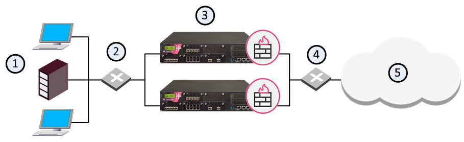
Item |
Description |
|---|---|
1 |
Internal network |
2 |
Switch for internal network |
3 |
Security Gateways with ClusterXL Software Blade |
4 |
Switch for external networks |
5 |
Internet |
R80.10 ClusterXL supports High Availability clusters for IPv6. IPv6 status information is synchronized and the IPv6 clustering mechanism is activated during failover. However, IPv6 is not supported for Load Sharing clusters. Also, you cannot define IPv6 addresses for synchronization interfaces.
ClusterXL uses State Synchronization to keep active connections alive and prevent data loss when a member fails. With State Synchronization, each member "knows" about connections that go through other members.
ClusterXL uses virtual IP addresses for the cluster itself and unique physical IP and MAC addresses for the members. Virtual IP addresses do not belong to physical interfaces.
ClusterXL can work with OPSEC certified High Availability and Load Sharing products, which use the same State Synchronization infrastructure as Check Point ClusterXL.
Note - The ClusterXL Administration Guide contains information only for Security Gateway clusters. For information about the use of ClusterXL with VSX, see the R80.10 VSX Administration Guide.
The Cluster Control Protocol (CCP) is the glue that links together the members in the Security Cluster. CCP traffic is distinct from ordinary network traffic and can be viewed using any network sniffer.
CCP runs on UDP port 8116, and has the following roles:
The Check Point CCP is used by all ClusterXL modes as well as by OPSEC clusters. However, the tasks performed by this protocol and the manner in which they are implemented may differ between cluster types.
Note - There is no need to add a rule to the Security Policy Rule Base that accepts CCP.
|
|
|
ClusterXL must be installed in a distributed configuration in which the Security Management Server and the Security Cluster members are on different computers. ClusterXL is part of the standard Security Gateway installation.
For installation instructions, see the R80.10 Installation and Upgrade Guide.
To see the ClusterXL supported platforms, see the R80.10 Release Notes .
ClusterXL is a software-based Load Sharing and High Availability solution that distributes network traffic between clusters of redundant Security Gateways.
ClusterXL has these High Availability features:
All members in the cluster are aware of the connections passing through each of the other members. The cluster members synchronize their connection and status information across a secure synchronization network.
The glue that binds the members in a ClusterXL cluster is the Cluster Control Protocol (CCP), which is used to pass synchronization and other information between the cluster members.
In a High Availability cluster, only one member is active (Active/Standby operation). In the event that the active cluster member becomes unavailable, all connections are re-directed to a designated standby without interruption. In a synchronized cluster, the standby cluster members are updated with the state of the connections of the active cluster member.
In a High Availability cluster, each member is assigned a priority. The highest priority member serves as the Security Gateway in normal circumstances. If this member fails, control is passed to the next highest priority member. If that member fails, control is passed to the next member, and so on.
Upon Security Gateway recovery, you can maintain the current active Security Gateway (Active Up), or to change to the highest priority Security Gateway (Primary Up).
ClusterXL High Availability supports IPv4 and IPv6.
ClusterXL Load Sharing distributes traffic within a cluster so that the total throughput of multiple members is increased. In Load Sharing configurations, all functioning members in the cluster are active, and handle network traffic (Active/Active operation).
If any member in a cluster becomes unreachable, transparent failover occurs to the remaining operational members in the cluster, thus providing High Availability. All connections are shared between the remaining Security Gateways without interruption.
IPv6 is not supported for Load Sharing clusters.
ClusterXL uses unique physical IP and MAC addresses for each cluster member, and a virtual IP addresses for the cluster itself. Cluster interface addresses do not belong to any real member interface.
The following diagram illustrates a two-member ClusterXL cluster, showing the cluster virtual IP addresses and member physical IP addresses. This sample deployment is used in many of the examples presented in this chapter.

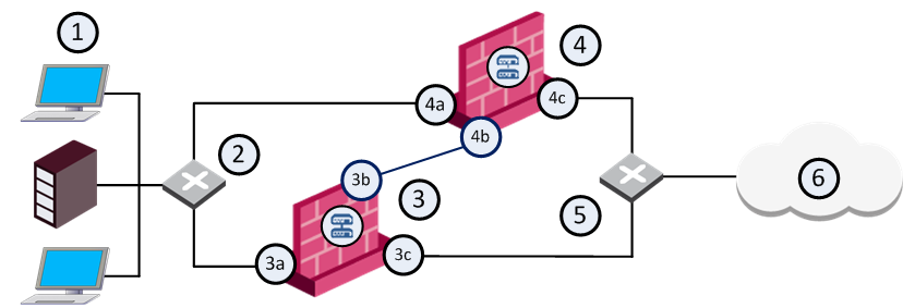
Item |
Description |
|---|---|
1 |
Internal network |
2 |
Internal switch (internal cluster IP address 10.10.0.100) |
3 |
Security Gateway - Cluster member A |
3a |
Virtual interface to the internal network (10.10.0.1) |
3b |
Interface to the Cluster Sync network (10.0.10.1) |
3c |
Virtual interface to the external network (192.168.10.1) |
4 |
Security Gateway - Cluster member B |
4a |
Virtual interface to the internal network (10.10.0.2) |
4b |
Interface to the Cluster Sync network (10.0.10.2) |
4c |
Virtual interface to the external network (192.168.10.2) |
5 |
External switch (external routable cluster IP address 192.168.10.100) |
6 |
Internet |
Each cluster member has three interfaces: one external interface, one internal interface, and one for synchronization. Cluster member interfaces facing in each direction are connected via a switch, router, or VLAN switch.
All cluster member interfaces facing the same direction must be in the same network. For example, there must not be a router between cluster members.
The Security Management Server can be located anywhere, and should be routable to either the internal or external cluster addresses.
The guidelines for configuring each cluster member are as follows:
All members within the cluster must have at least three interfaces:
All interfaces pointing in a certain direction must be on the same network.
For example, in the previous illustration, there are two cluster members, Member_A and Member_B. Each has an interface with an IP address facing the Internet through a hub or a switch. This is the external interface with IP address 192.168.10.1 on Member_A and 192.168.10.2 on Member_B, and is the interface that the cluster external interface sees.
Note - This release presents an option to use only two interfaces per member, one external and one internal and to run synchronization over the internal interface. This configuration is not recommended and should be used for backup only.
In the previous illustration, the IP address of the cluster is 192.168.10.100.
The cluster has one external virtual IP address and one internal virtual IP address. The external IP address is 192.168.10.100, and the internal IP address is 10.10.0.100.
State Synchronization between cluster members ensures that if there is a failover, connections that were handled by the failed member will be maintained. The synchronization network is used to pass connection synchronization and other state information between cluster members. This network therefore carries all the most sensitive security policy information in the organization, and so it is important to make sure the network is secure. It is possible to define more than one synchronization network for backup purposes.
To secure the synchronization interfaces, they should be directly connected by a cross cable, or in a cluster with three or more members, use a dedicated hub or switch.
Members in a Load Sharing cluster must be synchronized because synchronization is used in normal traffic flow. Members in a High Availability cluster do not have to be synchronized, though if they are not, connections may be lost upon failover.
The previous illustration shows a synchronization interface with a unique IP address on each member. 10.0.10.1 on Member_A and 10.0.10.2 on Member_B.
ClusterXL has these working modes. This section briefly describes each mode and its relative advantages and disadvantages.
The High Availability Mode provides basic High Availability capabilities in a cluster environment. This means that the cluster can provide firewall services even when it encounters a problem, which on a stand-alone Security Gateway would have resulted in a complete loss of connectivity. When combined with Check Point State Synchronization, ClusterXL High Availability can maintain connections through failover events, in a user-transparent manner, allowing a flawless connectivity experience. Thus, High Availability provides a backup mechanism, which organizations can use to reduce the risk of unexpected downtime, especially in a mission-critical environment (such as one involving money transactions over the Internet.)
To achieve this purpose, ClusterXL High Availability mode designates one of the cluster members as the active member, while the other members remain in stand-by mode. The cluster virtual IP addresses are associated with the physical network interfaces of the active member (by matching the virtual IP address with the unique MAC address of the appropriate interface). Thus, all traffic directed at the cluster is actually routed (and filtered) by the active member. The role of each cluster member is chosen according to its priority, with the active member being the one with the highest ranking. Member priorities correspond to the order in which they appear in the Cluster Members page of the Cluster Properties window. The top-most member has the highest priority. You can modify this ranking at any time.
In addition to its role as a firewall, the active member is also responsible for informing the stand-by members of any changes to its connection and state tables, keeping these members up-to-date with the current traffic passing through the cluster.
Whenever the cluster detects a problem in the active member that is severe enough to cause a failover event, it passes the role of the active member to one of the standby members (the member with the currently highest priority). If State Synchronization is applied, any open connections are recognized by the new active member, and are handled according to their last known state. Upon the recovery of a member with a higher priority, the role of the active member may or may not be switched back to that member, depending on the user configuration.
It is important to note that the cluster may encounter problems in standby members as well. In this case, these members are not considered for the role of active members, in the event of a failover.
Load Sharing Multicast Mode - This is an efficient way to handle a high load because the load is distributed optimally between all cluster members. Load Sharing Multicast mode associates a multicast MAC with each unicast cluster IP address. This ensures that traffic destined for the cluster is received by all members. The ARP replies sent by a cluster member will therefore indicate that the cluster IP address is reachable via a multicast MAC address.
Load Sharing Unicast Mode - Some routing devices will not accept ARP replies. For some routers, adding a static ARP entry for the cluster IP address on the routing device will solve the issue. Other routers will not accept this type of static ARP entry.
Another consideration is whether your deployment includes routing devices with interfaces operating in promiscuous mode. If on the same network segment there exists two such routers and a ClusterXL Security Gateway in Load Sharing Multicast mode, traffic destined for the cluster that is generated by one of the routers could also be processed by the other router.
For these cases, use Load Sharing Unicast Mode, which does not require the use of multicast for the cluster addresses.
Failover is a redundancy operation that automatically occurs of a member is not functional. When this happens, another member takes over for the failed member.
In a High Availability configuration, if one member in a synchronized cluster goes down, another member becomes active and "takes over" the connections of the failed member. If you do not use State Synchronization, existing connections are closed when failover occurs, although new connections can be opened.
In a Load Sharing configuration, if one member in a cluster is unavailable, its connections are distributed among the remaining members. All members in a Load Sharing configuration are synchronized, so no connections are interrupted.
To tell each member that the other members are alive and functioning, the ClusterXL Cluster Control Protocol maintains a heartbeat between cluster members. If after a predefined time, no message is received from a member, it is assumed that the cluster member is down and failover occurs. At this point, another member automatically assumes the functionality of the failed member.
It should be noted that a cluster member may still be operational, but if any of the above tests fail, then the faulty member starts the failover because it has determined that it can no longer function as a member.
Note that more than one cluster member may encounter a problem that will result in a failover event. In cases where all cluster members encounter such problems, ClusterXL will try to choose a single member to continue operating. The state of the chosen member will be reported as Active Attention. This situation lasts until another member fully recovers. For example, if a cross cable connecting the cluster members malfunctions, both members will detect an interface problem. One of them will change to the Down state, and the other to Active Attention.
A failover takes place when one of the following occurs on the active cluster member:
This procedure describes how to configure the Load Sharing Multicast, Load Sharing Unicast, and High Availability New Modes from scratch. Their configuration is identical, apart from the mode selection in SmartDashboard Cluster object or Cluster creation wizard.
|
Important - The hardware for all cluster members must be exactly the same, including:
|
To create new cluster members for ClusterXL:
During the installation process, enable ClusterXL and State Synchronization:
Run cpconfig
If you did not perform this action during installation, you can always do so by using the cpconfig utility at a later time. Run the cpconfig from the command line, and select the appropriate options to enable cluster capabilities for that member. You may be asked to reboot the member.
Note - You can also perform synchronization over a WAN
To configure routing for client computers:
The ClusterXL Control Protocol (CCP) uses multicast by default, because it is more efficient than broadcast. If the connecting switch cannot forward multicast traffic, it is possible, though less efficient, for the switch to use broadcast to forward traffic.
To change the CCP mode between broadcast and multicast, run:
cphaconf set_ccp broadcast|multicast
The Check Point Appliance or Open Server Wizard is recommended for enterprise grade appliances and open server platforms.
To create a new cluster with the Appliance or Open Server Wizard:
Important: You must define a corresponding IPv4 address for every IPv6 address. This release does not support pure IPv6 addresses.
Note: Make sure that you do not define IPV6 address for sync interfaces. The wizard does not let you define an interface with an IPv6 address as a sync interface.
The wizard automatically calculates the subnet for each network and assigns it to the applicable interface on each member. The calculated subnet shows in the upper section of the window.
The available network objectives are:
This option is recommended for the management interface.
After you finish the wizard, we recommend that you open the cluster object and do these procedures:
Virtual Router Redundancy Protocol (VRRP) provides dynamic failover of IP addresses from one router to another in the event of failure. This increases the availability and reliability of routing paths via gateway selections on an IP network. Each VRRP router has a unique identifier known as the Virtual Router Identifier (VRID) which is associated with at least one Virtual IP Address (VIP). Neighboring network nodes connect to the VIP as a next hop in a route or as a final destination. Gaia supports VRRP as defined in RFC 3768.
On Gaia, VRRP can be used with or without ClusterXL enabled. The most common use case is with ClusterXL enabled. This guide describes one way of configuring VRRP, known as Monitored Circuit/Simplified VRRP, with ClusterXL enabled. To learn about all the ways of configuring VRRP, and to use VRRP without ClusterXL enabled, see the Gaia Administration Guide.
With ClusterXL enabled, VRRP supports a maximum of one VRID with one Virtual IP Address (VIP) on every interface. Only active/backup environments are supported, and you must configure VRRP so that the same node is the VRRP master for all VRIDs. This means that you must configure each VRID to monitor every other VRRP-enabled interface. You must also configure priority deltas to allow failover to the backup node when the VRID on any interface does a failover.
Monitored Circuit/Simplified VRRP makes possible a complete node failover by automatically monitoring all VRRP-enabled interfaces. You configure one VRID, and this VRID is automatically added to all the VRRP interfaces. If the VRID on any interface fails, the configured priority delta is decremented on the other interfaces. This allows the backup node to take over as the VRRP master.
Each Virtual Router (VRRP Group) is identified by a unique Virtual Router ID (VRID). A Virtual Router contains one Master Security Gateway, and at least one Backup Security Gateway. The master sends periodic VRRP advertisements (known as hello messages) to the backups.
VRRP advertisements broadcast the operational status of the master to the backups. Gaia uses dynamic routing protocols to advertise the VIP (virtual IP address or backup address) of the Virtual Router.
If the master or its interfaces fails, VRRP uses a priority algorithm to decide if failover to a backup is necessary. Initially, the master is the Security Gateway that has the highest defined priority value. You define a priority for each Security Gateway when you create a Virtual Router or change its configuration. If two Security Gateways have same priority value, the platform that comes online and broadcasts its VRRP advertisements first, becomes the master.
Gaia also uses priorities to select a backup Security Gateway upon failover (when there is more than one backup available). In the event of failover, the Virtual Router priority value is decreased by a predefined Priority Delta value to calculate an Effective Priority value. The Virtual Router with the highest effective priority becomes the new master. The Priority Delta value is a Check Point proprietary parameter that you define when configuring a Virtual Router. If you configure your system correctly, the effective priority will be lower than the backup gateway priority in the other Virtual Routers. This causes the problematic master to fail over for the other Virtual Routers as well.
Note- If the effective priority for the current master and backup are the same, the Gateway with the highest IP address becomes the master.
This is a simple VRRP high availability use case where Security Gateway 1 is the master and Security Gateway 2 is the backup. Virtual Router redundancy is available only for connections to and from the internal network. There is no redundancy for external traffic.
Item |
Description |
|---|---|
1 |
Master Security Gateway |
2 |
Backup Security Gateway |
3 |
Virtual Router VRID 5 - Virtual IP Address (Backup Address) is 192.168.2.5 |
4 |
Internal Network and hosts |
Do these steps before you start to define a Virtual Router (VRRP Group).
Best Practice - We recommend that you enable NTP (Network Time Protocol) on all Security Gateways.
You can also manually change the time and time zone on each Security Gateway to match the other members. In this case, you must synchronize member times to within a few seconds.
Best Practice - If you use the Spanning Tree protocol on Cisco switches connected to Check Point VRRP clusters, we recommend that you enable PortFast. PortFast sets interfaces to the Spanning Tree forwarding state, which prevents them from waiting for the standard forward-time interval.
If you use switches from a different vendor, we recommend that you use the equivalent feature for that vendor. If you use the Spanning Tree protocol without PortFast, or its equivalent, you may see delays during VRRP failover.
When you log into Gaia for the first time after installation, you must use the First Time Configuration Wizard to the initial configuration steps. To use VRRP Virtual Routers (clusters), you must first enable VRRP clustering in the First Time Configuration Wizard.
To enable VRRP clustering:
cpconfigEnable cluster membership for this gateway Note - This is the most common use and does not support active/active mode. You must configure VRRP so that the same cluster member is the VRRP master on all interfaces. Dynamic routing configuration must match on each cluster member.
OR:
Note - This is useful when each cluster member is required to be the VRRP master at the same time. You can configure two VRRP Virtual Routers on the same interface. Each cluster member can be the VRRP master for a different VRID on the same interface while it backs up the other. This configuration can also help run VRRP in a High-Availability pair with a device from another vendor. Disable the VRRP monitoring of the Firewall when you use this configuration. It is enabled by default but not supported with this configuration. Also, only Static Routes are supported with this configuration.
yDo this procedure for each Virtual Router member.
When you complete this procedure for each VRRP member, do these steps in the Gaia WebUI:
When you complete these procedures, define your Virtual Routers using the Gaia WebUI or the Gaia Clish.
This section includes shows you how to configure the global settings. Global settings apply to all Virtual Routers.
Configure these global settings:
Cold Start Delay - Delay period in seconds before a Security Gateway joins a Virtual Router. Default = 0.
Interface Delay - Configure this when the Preempt Mode of VRRP has been turned off. This is useful when the VRRP node with a higher priority is rebooted, but must not preempt the existing VRRP master that is handling the traffic, but is configured with a lower priority. Sometimes interfaces that come up take longer than the VRRP timeout to process incoming VRRP Hello packets. The Interface Delay extends the time that VRRP waits to receive Hello packets from the existing master.
Disable All Virtual Routers - Select this option to disable all Virtual Routers defined on this Gaia system. Clear this option to enable all Virtual Routers. By default, all Virtual Routers are enabled.
Monitor Firewall State - Select this option to let VRRP monitor the Security Gateway and automatically take appropriate action. This is enabled by default, which is the recommended setting when using VRRP with ClusterXL enabled. This must be disabled when using VRRP with ClusterXL disabled.
Important - If you disable Monitor Firewall State, VRRP can assign master status to a Security Gateway before it completes the boot process. This can cause more than one Security Gateway in a Virtual Router to have master status.
Configuration Notes:
Gaia starts to monitor the firewall after the cold start delay completes. This can cause some problems:
This section includes the basic procedure for configuring a Virtual Router using the Gaia WebUI.
To add a new Virtual Router:
You must use the same authentication method for all Security Gateways in a Virtual Router.
If you select simple, enter a password in the applicable field.
Note - If you configure different VMACs on the master and backup, you must make sure that you select the correct proxy ARP setting for NAT.
Note - If you set the VMAC mode to Interface or Static, syslog error messages show when you restart the computer or during failover. This is caused by duplicate IP addresses for the master and backup. This is expected behavior because the master and backups temporarily use the same virtual IP address until they get master and backup status.
Click Save. The new VMAC mode shows in the in the Backup Address table.
The Security Gateway Cluster Creation window opens
Source |
Destination |
VPN |
Services & Applications |
Action |
Firewalls (Group) |
|
|
|
|
Where:
Alternatively, you can create a Network object to show all multicast network IP destinations with these values:
MCAST.NET224.0.0.0240.0.0.0You can use one rule for all multicast protocols you agree to accept, as shown in this example:
Source |
Destination |
VPN |
Services & Applications |
Action |
Cluster all IP addresses |
fwcluster-object |
|
|
|
To learn more about maximizing network performance and redundancy, see these R80.10 guides:

