


|
|
|
A connection is called sticky if a single Cluster Member handles all packets of that connection. In a non-sticky connection, the response packet of a connection returns through a different Cluster Member than the original request packet.
The cluster synchronization mechanism knows how to handle non-sticky connections properly. In a non-sticky connection, a Cluster Member can receive an out-of-state packet, which Firewall normally drops because it poses a security risk.
In Load Sharing configurations, all Cluster Members are active. In Static NAT and encrypted connections, the source and destination IP addresses change. Therefore, Static NAT and encrypted connections through a Load Sharing cluster may be non‑sticky. Non-stickiness may also occur with Hide NAT, but ClusterXL has a mechanism to make it sticky.
In High Availability configurations, all packets reach the Active member, so all connections are sticky. If failover occurs during connection establishment, the connection is lost, but synchronization can be performed later.
If the other members do not know about a non-sticky connection, the packet will be out-of-state, and the connection will be dropped for security reasons. However, the Synchronization mechanism knows how to inform other members of the connection. The Synchronization mechanism thereby prevents out-of-state packets in valid, but non‑sticky connections, so that these non-sticky connections are allowed.
Non-sticky connections will also occur if the network Administrator has configured asymmetric routing, where a reply packet returns through a different Security Gateway than the original packet.
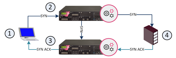
The 3-way handshake that initiates all TCP connections can very commonly lead to a non-sticky (often called asymmetric routing) connection. This diagram shows a sample scenario:
Item |
Description |
|---|---|
1 |
Client |
2 |
Security Gateway - Cluster Member A |
3 |
Security Gateway - Cluster Member B |
4 |
Server |
The client initiates a connection by sending a SYN packet to the server. The SYN passes through Cluster Member A, but the SYN/ACK reply returns through Cluster Member B. This is a non-sticky connection, because the reply packet returns through a different Security Gateway than the original packet.
The synchronization network notifies Cluster Member B. If Cluster Member B is updated before the SYN/ACK packet sent by the server reaches it, the connection is handled normally. If, however, synchronization is delayed, and the SYN/ACK packet is received on Cluster Member B before the SYN flag has been updated, then the Security Gateway treats the SYN/ACK packet as out-of-state, and drops the connection.
You can configure enhanced 3-Way TCP Handshake enforcement to address this issue.
The synchronization mechanism prevents out-of-state packets in valid, but non-sticky connections. The way it does this is best illustrated with reference to the 3-way handshake that initiates all TCP data connections. The 3-way handshake proceeds as follows:
To prevent out-of-state packets, the following sequence (called "Flush and Ack") occurs
Organizations sometimes need to locate Cluster Members in geographical locations that are distant from each other. A typical example is a replicated Data Center, whose locations are widely separated for disaster recovery purposes. In such a configuration, it is clearly impractical to use a cross cable for the synchronization network.
The synchronization network can be spread over remote sites, which makes it easier to deploy geographically distributed clustering. There are two limitations to this capability:
You can monitor and troubleshoot geographically distributed clusters using the command line interface.
The following restrictions apply when you synchronize Cluster Members:
Synchronization interface redundancy is not supported for VRRP Clusters. See sk92804.
The reason for these restrictions is that the user authentication state is maintained by a process on the Security Gateway. It cannot be synchronized on Cluster Members in the same way as kernel data is synchronized. However, the states of Session Authentication and Client Authentication are saved in kernel tables, and can be synchronized.

