


|
|
|
Make Internet connectivity more reliable with ISP Redundancy. This connects a Security Gateway or Cluster Member to the Internet through redundant Internet Service Provider (ISP) links. ISP Redundancy monitors the ISP links and chooses the best current link.
R80.10 supports two ISPs.
If you have a ClusterXL Cluster, connect each Cluster Member to the two ISPs through a LAN with two interfaces. The member interfaces must be on the same subnet as the cluster external interfaces. Configure ClusterXL in the usual way.
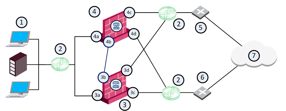
Item |
Description |
|---|---|
1 |
Internal network |
2 |
VLAN switches |
3 |
Security Gateway - Cluster Member A |
3a |
Virtual interface to the internal network (10.10.0.1) |
3b |
Interface to the Cluster Sync network (10.0.10.1) |
3c |
Virtual interface to ISP B (172.16.2.2) |
3d |
Virtual interface to VLAN switch that connects to ISP A (192.168.1.3) |
4 |
Security Gateway - Cluster Member B |
4a |
Virtual interface to the internal network (10.10.0.2) |
4b |
Interface to the Cluster Sync network (10.0.10.2) |
4c |
Virtual interface to ISP A (192.168.1.2) |
4d |
Virtual interface to VLAN switch that connects to ISP B (172.16.2.3) |
5 |
Router that connects to ISP A (192.168.1.1) |
6 |
Router that connects to ISP B (172.16.2.1) |
7 |
Internet |
You can configure the ISP preference to be for Load Sharing or Primary/Backup.
Load Sharing - Uses the two links with a distributed load of connections going out from the Security Gateway. Connections coming in are alternated. You can configure best relative loads for the links (set a faster link to handle more load). New connections are randomly assigned to a link. If one link fails, the other takes the load.
Primary/Backup - Uses one link for connections going out from the Security Gateway and coming in. It switches to the backup if the primary link fails. When the primary link is restored, new connections are assigned to it. Existing connections continue on the backup link until they are complete.
Note: ISP Redundancy settings override VPN Link Selection settings.
To enable ISP Redundancy:
Before you begin, make sure you have the ISP data - the speed of the link and next hop IP address. If the Security Gateway has only one external interface, configure two subnets on this interface. You will need routers and a switch.
If the Security Gateway has two external interfaces in the Network Management page of the gateway object, you can configure the links automatically.
If the gateway is a ClusterXL Cluster Member, configure the two Cluster Members to the two ISP. Use a LAN with two interfaces. Make sure the member interfaces are on the same subnet as the cluster external interfaces.
To configure ISP links automatically:
The ISP Links are added automatically.
To configure ISP links manually:
Note the names you give here. They are used in the ISP Redundancy script and commands.
The Security Gateway, or a DNS server behind it, must respond to DNS queries. It resolves IP addresses of servers in the DMZ (or another internal network).
Get a public IP address from each ISP. If public IP addresses are not available, register the domain to make the DNS server accessible from the Internet.
To enable DNS on the Security Gateway or cluster:
The Security Gateway or cluster intercepts Type A DNS queries for the web servers in its domain that come from external hosts. If the Security Gateway or cluster recognizes the external host, it replies:
If the Security Gateway or cluster does not recognize the host, it passes the DNS query on to the original destination, or to the domain DNS server.
This sets a Time To Live for each DNS reply. DNS servers in the Internet cannot cache your DNS data in the reply for longer than the TTL.
Note - If the servers use different services (for example, HTTP and FTP), you can use NAT for only two public IP addresses.
To register the domain and get IP addresses:
The Firewall must allow connections through the ISP links, with Automatic Hide NAT on network objects that start outgoing connections.
To configure the firewall for ISP Redundancy:
If you have one public IP address from each ISP for the Security Gateway, define Static NAT. Allow specific services for specific servers. For example, make NAT rules so that incoming HTTP connections from the two ISP reach a Web server, and DNS traffic from the ISP reach the DNS server.
Example: Manual Static Rules for a Web Server and a DNS Server
Original Source |
Original Destination |
Original Service |
Original Source |
Translated Destination |
Translated Services |
Comment |
|
IP of web server |
|
= |
10.0.0.2 (Static) |
= |
Incoming Web - ISP A |
|
IP of web server |
|
= |
10.0.0.2 (Static) |
= |
Incoming Web - ISP B |
|
IP of DNS server |
|
= |
10.0.0.3 (Static) |
= |
Incoming DNS - ISP A |
|
IP of DNS server |
|
= |
10.0.0.3 (Static) |
= |
Incoming DNS - ISP B |
If you have a public IP address from each ISP for each publicly reachable server (in addition to the Security Gateway), define NAT rules:
Note - If using Manual NAT, automatic ARP does not work for the NATed IP addresses. You need to configure the local.arp file as described in sk30197.
When done, install the Access Control Policy on this cluster object.
When ISP Redundancy is enabled, VPN encrypted connections survive a failure of an ISP link. The settings in the ISP Redundancy page override settings in the IPsec VPN > Link Selection page.
To configure ISP Redundancy with VPN on cluster:
VPN Link Selection now only probes the ISP configured in ISP Redundancy.
To configure for VPN with a third-party peer:
If the VPN peer is not a Check Point Security Gateway, the VPN may fail, or the third-party device may continue to encrypt traffic to a failed ISP link.
Use the fw isp_link command to force the ISP link state to Up or Down. Use this to test installation and deployment, or to force the Security Gateway to recognize the true link state if it cannot (the ISP link is down but the gateway sees it as up).
You can run this command on the Security Gateway or the Security Management Server: fw isp_link [target-gw] <link_name> {up|down}
<link_name> is the name in the ISP Link window.
When the Security Gateway starts, or an ISP link state changes, the $FWDIR/bin/cpisp_update script runs. It changes the default route of the Security Gateway. For example, you can force the Security Gateway to change the state of a dialup interface to match that state of its ISP link.
Edit this script to enable a dialup connection for one of the ISP links.
To configure a dialup connection:
fw isp_link <link_name> down fw isp_link <link_name> up
