Bridge Mode
Introduction to Bridge Mode
Bridge Interfaces
Bridge interfaces connect two different interfaces (bridge ports). Bridging two interfaces causes every Ethernet frame that is received on one bridge port to be transmitted to the other port. Thus, the two bridge ports participate in the same Broadcast domain (which is different from router ports behavior).
Only two interfaces can be connected by a single Bridge interface. These two interfaces can then be thought of as a two-ports switch. Each port can be a physical, VLAN, or bond device.
Bridge interfaces can be configured on Check Point Security Gateway, and can be used for different deployments. The Firewall inspects every Ethernet frame that passes through the bridge.
Supported Software Blades: Gateway and Virtual Systems
These Software Blades support bridge mode (unless stated they do not) for single Security Gateway deployment, cluster with one switch in Active/Active and Active/Standby deployment, and cluster with four switches.
Supported Blade
|
Supports Gateways in Bridge Mode
|
Supports Virtual Systems in Bridge Mode
|
Firewall
|
Yes
|
Yes
|
IPS
|
Yes
|
Yes
|
URL Filtering
|
Yes
|
Yes
|
DLP
|
Yes
|
No
|
Anti-Bot and Anti-Virus
|
Yes
|
Yes
|
Application Control
|
Yes
|
Yes
|
HTTPS Inspection
|
Yes
|
No
|
Identity Awareness
|
Yes
|
No
|
Threat Emulation
|
Yes
|
Yes
|
QoS
|
Yes
|
No
|
Client Authentication
|
No
|
No
|
User Authentication
|
No
|
No
|
Supported Software Blades: Management
Bridge-mode for a Security Management Server is supported only for Standalone configurations, and it supports all management Software Blades.
Unsupported for Bridge Mode
These features, Software Blades and deployments are not supported in Bridge Mode:
- Mobile Access Software Blade
- IPsec VPN Software Blade
- Full High Availability deployment
- NAT on Gateways
- Access to Portals from bridged networks, if the bridge does not have an assigned IP address
- Anti-Virus Traditional Mode
- Identity Awareness authentication other than AD Query (AD Query is the only supported authentication)
Supported Operating Systems
These operating systems support Bridge Mode configurations:
For more about configuring Bridge Mode for an IPSO Security Gateway, see How To Setup a Bridge Mode Firewall on an IP Appliance with IPSO.
Configuring Bridge Interfaces
Using the Gaia WebUI
To configure a bridge interface with the WebUI:
- In the WebUI navigation tree, select .
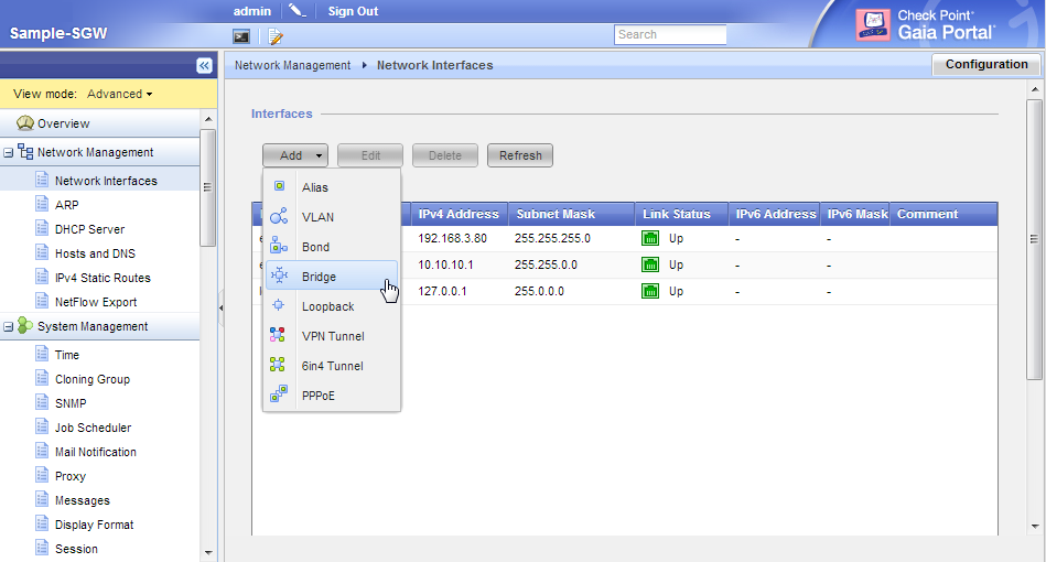
- Click > .
The window opens.
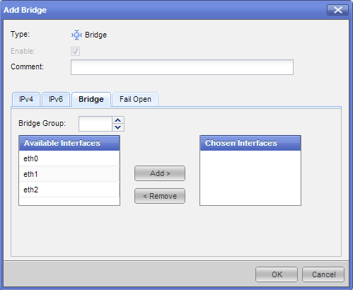
- On the tab, enter or select a ID (unique integer between 0 and 1024).
- Select the interfaces from the list and then click .
- Click .
Using the CLI
Bridge interfaces are known as in Gaia clish commands. You can optionally assign an IPv4 or IPv6 address to a bridge interface.
To create a new bridging group:
Run:
> add bridging group <Group ID>
<Group Name>
To add an interface to the bridging group:
Run:
>add bridging group <Group ID> interface <interface>
<interface>
Run this command once for each physical interface included in the bridge interface.
To delete an interface from the bridging group:
Run:
> delete bridging group<Group ID> interface <IF>
Run this command once for each physical interface included in the bridge interface.
To delete a bridging group:
Run:
> delete bridging group <Group ID>
To add or change a bridge interface IP address:
- For an IPv4 IP address, run
> set interface <interface> ipv4-address <IP> subnet-mask <Mask> - For an IPv6 IP address, run
> set interface <interface> ipv6-address <IP> mask-length <Prefix>.<interface>
<IP>
<Mask>
<Prefix>
Example:
set interface br1 ipv6-address 3000:40::1 mask-length 64
Bridging group commands
This is a quick reference for bridge interface commands.
Description - Use these commands to configure bridge interfaces.
Syntax
add bridging group <Group ID> [interface <interface>]
delete bridging group <Group ID> interface <interface>
show bridging group <Group ID>
Parameters
Parameter
|
Description
|
<Group ID>
|
ID of bridging group
|
<interface>
|
Interface name
|
Example - add bridging group 56 interface eth1

|
Important - After using CLI commands to add, configure or delete features, you must run the save config
|
Configuring Bridge Mode for Gateways
You can configure bridge mode with a single gateway or with a cluster. VSX bridge deployments are explained later.
The bridge can work without an assigned IP address.
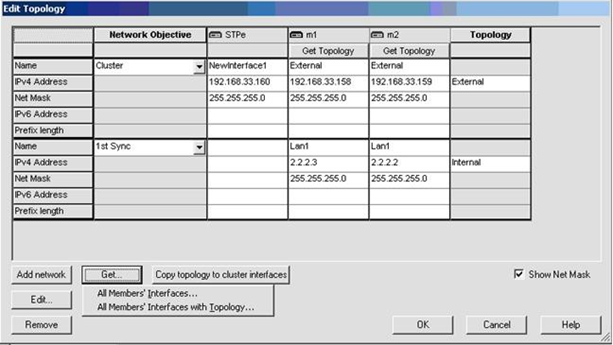
SmartDashboard helps you configure the topology for the bridge ports. There is a separate network or group object that represents the networks or subnets that connect to each port.
Configuring Single Gateway in Bridge Mode
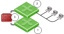
|
Item
|
Description
|
1 and 2
|
Switches
|
3
|
Security Gateway Firewall bridging Layer-2 traffic over the one IP address, with a subnet on each side using the same address.
|
Before you begin, configure a dedicated management interface.
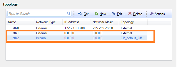
First you configure the bridge interface. Then you define the bridge topology in SmartDashboard.
To define the bridge topology:
Use SmartDashboard to manually configure the topology for the bridge ports:
- If one of the bridge ports connects to the Internet, set the topology to
- If the topology uses Anti-Spoofing, for the internal port (interface), make sure that you:
- Set the topology to
- Select the Specific network that connects to the port
- If the topology does not use Anti-Spoofing, make sure that you disable Anti-Spoofing on the bridge port

|
Note - When you use Internet objects in a rule with a Security Gateway, make sure that the bridge interface is defined as .
|
Configuring an IP Address for the Bridge
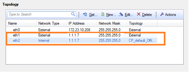
In a Security Gateway bridge deployment, you can configure an IP address for the bridge. The IP address of the bridge must be in the bridged subnet. The bridge IP address can be used for gateway management and access to the gateway portals.
When you assign an IP address to the bridge, the window shows that both bridge ports have the same IP address as the bridge.
Configuring Gateway Cluster in Bridge Mode
You can configure cluster gateways for bridge mode in different deployments:
- Active/Standby mode
- Active/Active mode
|
Item
|
Description
|
1 and 2
|
Switches
|

|
Security Gateway Firewall bridging Layer-2 traffic
|
3
|
eth1
|
4
|
eth2
|
5
|
eth3 - the ClusterXL Sync interface
|
Configuring Active/Standby Mode
This is the preferred mode in topologies that support it.
In Active-Standby mode, ClusterXL decides the cluster state. The standby member drops all packets. It does not pass any traffic, including STP/RSTP/MSTP. If there is a failover, the switches are updated by the Security Gateway to forward traffic to the new active member.
If you use this mode, it is best to disable STP/RSTP/MSTP on the adjacent switches.
To configure Active/Standby mode:
- Configure the cluster.
- Run:
cpconfig - Enter
8 - Confirm:
y - Reboot the cluster member.
- Install Policy.
- Test the cluster state:
cphaprob statThe output should be similar to:
Cluster Mode: High Availability (Active Up, Bridge Mode) with IGMP Membership
Number Unique Address Firewall State (*)
1 (local> 2.2.2.3 Active
2 2.2.2.2 Standby
Configuring Active/Active Mode
When you define a bridge interface on a Security Gateway cluster, Active/Active mode is activated by default.
Before you begin, install ClusterXL High Availability on a Gaia appliance or open server.
To configure Active/Active mode, do these steps on each member of the cluster:
- Configure dedicated management and Sync interfaces.
- Add a bridge interface, as in a single gateway deployment.
Do not configure an IP address on the newly created bridge interface.
- In SmartDashboard, add the cluster object:
- Open of the cluster object.
- Get the cluster topology.
- Make sure the dedicated management and Sync interfaces are configured.
- Make sure the bridge interface and bridge ports are not in the topology.
Bridge port topology cannot be defined. It is by default.
- Install Policy.
- Test the cluster state:
cphaprob statThe output should be similar to:
Cluster Mode: High Availability (Active Up, Bridge Mode) with IGMP Membership
Number Unique Address Firewall State (*)
1 (local> 2.2.2.3 Active
2 2.2.2.2 Active
- Make sure that cluster is configured as High Availability in SmartDashboard.
Confirming the High Availability Configuration
When you finish configuring Active/Active mode, the output for chpaprob statFirewall State is Active/Active
To confirm the High Availability configuration:
- From SmartDashboard, double-click the cluster object.
The cluster window opens and shows the page.
- From the navigation tree, click .
- In the section, make sure that is selected.
- Click .
Cluster Between Four Switches
You can configure a bridged cluster between four switches, in Active/Active mode.
Active/Standby mode is not supported.
Item
|
Description
|
1, 2, 3, 4
|
Switches
|
|
Security Gateway Firewall bridging Layer-2 traffic
|
5
|
eth1
|
6
|
eth2
|
7
|
eth3 - the ClusterXL Sync interface
|
See also: Link Aggregation with ClusterXL in Layer-2
Routing and Bridges
Security Gateways with a bridge interface can support Layer 3 routing over non-bridged interfaces. If you configure a bridge interface with an IP address for one Security Gateway (not a cluster), the bridge functions as a regular Layer 3 interface. It participates in IP routing decisions on the gateway and supports Layer 3 routing.
- Cluster deployments do not support this configuration.
- You cannot configure the bridge to be the route gateway.
- One Security Gateway can support multiple bridge interfaces, but only one bridge can have an IP address.
- The Security Gateway cannot filter or transmit packets on a bridge interface that it inspected before (double-inspection).
Management over Bridge
The following diagram shows a sample topology:
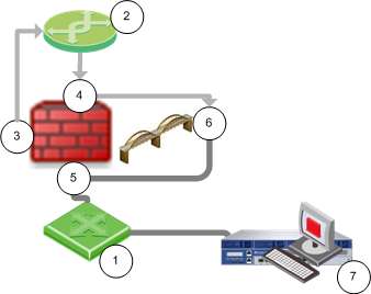
Item
|
Description
|
1
|
Switch
|
2
|
Router
|
|
Security Gateway Firewall bridging Layer-2 traffic
|
3
|
Management interface (inspects first packet)
|
4
|
eth1 (inspects first packet again)
|
5
|
eth2
|
6
|
Bridge interface - Management traffic drops
|
7
|
Security Management Server
|
When a Layer-3 management interface sends traffic through the firewall, the traffic is dropped because it cannot inspect the same packet again.
- The first packet is inspected and then goes from the management interface to the router.
- The router sends the packet to the bridge interface, and the firewall inspects the first packet again. The firewall concludes that this packet is a retransmission and then drops it.
Use the procedure for the applicable Security Gateway version.
Security Gateways R77.10 and Higher
This feature is supported in R77.10 and higher.
You can configure the Security Gateway to recognize that the first packet is from the management interface. The firewall makes sure that the MD5 hash of the packet that leaves the management interface and enters the bridge interface is the same. Other packets in this connection are handled by the bridge interface without using the router.
To enable management over the bridge:
- Edit
$FWDIR/boot/modules/fwkern.confIf necessary, create this file.
- Add the appropriate line to the file:
- For IPv4 traffic -
fwx_bridge_reroute_ipv4=<management> - For IPv6 traffic -
fwx_bridge_reroute_ipv6=<management>
<management>
- Reboot the Security Gateway.
Security Gateways R77 and Earlier
Incoming and outgoing traffic from a Layer-3 management interface is dropped if traversed over a bridge interface. You can make this traffic pass. Disable inspection on the management interface and disable local Anti-Spoofing.
Note: This removes inspection from the management interface and could compromise gateway security. If you are unsure whether your environment is safe to use this method, contact Check Point Solution Center.
To configure management over the bridge:
- Open
$PPKDIR/boot/modules/simkern.conf simlinux_excluded_ifs_list=(Create this file if not found.)
Where the value (interface name) is the management interface name.
This excludes the management interface from SecureXL.
- Edit $
FWDIR/modules/fwkern.conf(Create this file if not found.)
Add these lines:
fwx_bridge_use_routing=0
fw_local_interface_anti_spoofing=0
fwlinux_excluded_ifs_list=
Where the value (interface name) is the management interface name.
This disables local Anti-Spoofing and bridge routing, and excludes the management interface from security inspection.
- Reboot.
|

