QoS Tutorial
Introduction
This chapter presents a step by step guide to building and installing a QoS Policy in QoS. This tutorial is based on the network configuration shown below.
This tutorial is based on a simple network configuration, but working through it will familiarize you with the many issues involved in building and installing a QoS Policy. Each step in the process is described in detail so that by the end of this tutorial you will have developed a practical knowledge of building and installing a usable QoS policy.
The tutorial walks you through the steps involved in physically installing a network, and then introduces you to SmartDashboard and QoS, in which you configure the network and implement QoS policy.
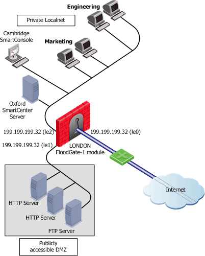
This example shows a typical network configuration for an organization with offices located in London, Oxford and Cambridge. The QoS gateway is located in London where the gateway to the Internet will comprise three interfaces. The Security Management Server is located at Oxford while the SmartConsole is installed at Cambridge. Within the private local network there are the Marketing and Engineering departments. In this tutorial you are shown how a QoS policy is implemented to regulate and optimize the flow in Internet traffic to these departments.
Building and Installing a QoS Policy
The following steps represent the workflow that must be followed in order to build and install a QoS Policy on the illustrated. Each of these steps is then described in detail in the sections that follow:
- Install the appropriate gateways on each machine, as needed.
Check Point gateways to Install on Each Machine
|
|
|
|
|
Computer
|
Function
|
Required gateway
|
London
|
QoS gateway; the Gateway to the Internet
|
QoS gateway
Security Gateway (required)
|
Oxford
|
Security Management Server
|
Security Management Server QoS Add-on
|
Cambridge
|
SmartConsole
|
Security Gateway
|

|
Note - In order to manage QoS gateways, you need to install QoS on the Security Management Server as well as on the gateway.
|
- Start SmartDashboard and display the QoS tab.
- Determine the type of QoS Policy you want to implement.
- Define the network objects to be used in the Rule Base.
You define only those objects that are explicitly used in the Rule Base and do not have to define the entire network.
- Define any proprietary services used in your network.
You do not have to define the commonly used services. These are already defined for you in QoS. In most cases, you need only specify a name, for network objects and services because QoS obtains the object's properties from the appropriate databases (DNS, YP. hosts file).
- Create a new QoS Rule Base and the rules that comprise that Rule BaseRule Base.
- Install the Rule Base on the QoS gateway machine, which will enforce the QoS Policy.
These steps are described in detail in the sections that follow.
Installing Check Point Gateways
This step describes the physical installation of the products at the various locations in the example on page 52. In this tutorial you do not physically install the network but you do run the QoS gateway on SmartDashboard.
Detailed installation instructions are available in the R77 Installation and Upgrade Guide.
Install QoS in this sequence:
- Install QoS and Firewall on London.
- Install SmartConsole on Cambridge.
- Install Security Management Server on Oxford.
- On Oxford, define Cambridge as a SmartConsole.
- On Oxford, define the administrators who will be allowed to manage the QoS Policy.
- Establish a secure connection (SIC) between the Security Management Server at Oxford and the QoS gateway at London.
Starting SmartDashboard
You must start SmartDashboard in order to be able to access QoS. For the purposes of this tutorial, and although all the regular log on procedures are described in this section, you must run SmartDashboard in Demo Mode, selecting the Advanced option. This section describes how to start SmartDashboard and access its QoS tab to be able to enter and install the QoS Policy you are defining.
To Start SmartDashboard
- From the Start menu, select Programs > Check Point SmartConsole > SmartDashboard. The Welcome to Check Point SmartDashboard window displays.
- You can log in using either your:
- Select User Name.
- Enter your user name and password in the designated field.
- Select Certificate.
- Select the name of your certificate file from the list or browse to it.
- Enter the password you used to create the certificate in the Password field.
- Enter the name of the machine on which the Security Management Server is running. You can enter one of the following:
- A resolvable machine name
- An IP address
- To work in local mode, check Demo Mode and select Advanced from the drop‑down list.
- (Optional) Check Read Only if you do not wish to modify a policy,
- (Optional) Click More Options > to display the Certificate Management and Advanced Options.
- (Optional) Click Change Password to change the certificate password.
- (Optional) Check Use compressed connection to compress the connection to the Security Management Server.
- (Optional) Enter the text describing why the administrator wants to make a change in the security policy in the Session Description field. The text appears as a log entry in the SmartView Tracker in the Session Description column (in Audit mode only).
|
Note - If the Session Description column does not appear in the SmartView Tracker, use the Query Properties pane to display it. For more on SmartView Tracker, see the R77 SmartView Tracker Administration Guide.
|
- (Optional) Check Do not save recent connections information if you do not want your connection settings saved.
- Click Less Options to hide the Certificate Management and Advanced options.
- Click OK.
The SmartDashboard main window opens.
- Click the QoS tab to display the QoS Rule Base.
Determining QoS Policy
To implement an effective QoS Policy, you must first determine how you currently use your network, and then identify and prioritize the types of traffic and the users who are going to use the network.
For example, a typical QoS Policy would be:
- HTTP traffic should be allocated more bandwidth than RealAudio.
- Marketing should be allocated more bandwidth than Engineering.
You will create the rules to implement this policy in Creating a Rule Base.
Defining the Network Objects
You must now define the Network Objects including London, the gateway on which the QoS gateway is running, and its interfaces, as well as the sub-networks for the Marketing and Engineering departments.
This step describes, as an example, how the gateway London will be defined.
Using one of the methods shown in the table, open the Properties window.
Creating a New Gateway
From the...
|
Do this...
|
Manage menu
|
- From the Manage menu, choose Network Objects.
The Network Objects window opens.
- Click New and choose Check Point > Gateway from the menu.
The Check Point Gateway - General Properties window opens.
|
Objects toolbar
|
- If the Objects toolbar is not visible, then, from the View menu choose Toolbars > Objects to display it.
- Select from the toolbar.
The Network Objects window opens.
- Click New and choose Check Point > Gateway from the menu. The Check Point Gateway -
General Properties window opens.
|
Network Objects tree
|
- Right click Network Objects in the Network Objects tree and choose New > Check Point > Gateway from the menu.
The Check Point Gateway - General Properties window opens.
- In the Check Point Gateway - General Properties window enter the information shown in the next table below to define London's gateway.
|
London's Check Point Gateway - General Properties Window
Field
|
Value
|
Explanation
|
Name
|
London
|
This is the name by which the object is known on the network; the response to the hostname command.
|
IP Address
|
192.32.32.32
|
This is the interface associated with the host name in the DNS — get this by clicking Get Address.
For gateways, this should always be the IP address of the external interface.
|
Comment
|
QoS gateway (gateway)
|
This is the text that is displayed at the bottom of the Network Objects window when this object is selected
|
Check Point Products
|
- Select the Version from the drop‑down list.
|
These settings specify the Check Point products installed on London, and their version number.
Note that if multiple Check Point products are installed on a machine, they must all be the same version number.
|
SIC
|
|
Establishes a secure communication channel between Check Point gateways.
|
Defining Interfaces on the Gateway
- Click Topology in the tree on the left side of the Check Point Gateway -London window.
The Topology page Check Point Gateway - London window is displayed.
- The easiest and most reliable way to define the interfaces is to click Get, which automatically retrieves general and topology information for each interface. If you choose this method of configuring the gateway, the topology fetched suggests the external interface of the gateway based on the QoS gateway routing table. You must ensure that this information is correct.
- Alternatively, click Add. The Interface Properties window is displayed.
- Enter the information on the three interfaces listed in the tables in the General and Topology tabs of this window.
- Click OK after you have entered the information from each table to add the interface to the Check Point Gateway - London - Topology window.
The data for each of the three interfaces of London is as follows:
Field Values — Interface Properties Window
|
|
|
Field
|
Value
|
Explanation
|
General tab
|
Name
|
le0
|
|
Net Address
|
192.32.32.32
|
|
Net Mask
|
255.255.255.0
|
|
Topology tab
|
Topology
|
Check External (leads out to the Internet).
|
Specifies to which network this interface leads.
|
Anti-Spoofing
|
Check Perform Anti-Spoofing based on network topology.
|
Specifies that each incoming packet will be examined to ensure that its source IP address is consistent with the interface through which it entered the machine.
|
Spoof Tracking
|
Check Log.
|
Specifies that when spoofing is detected, the event will be logged.
|
Field Values — Interface Properties Window — le1
|
|
|
Field
|
Value
|
Explanation
|
General tab
|
Name
|
le1
|
|
Net Address
|
192.32.42.32
|
|
Net Mask
|
255.255.255.0
|
|
Topology tab
|
Topology
|
Check External (leads out to the Internet).
|
Specifies to which network this interface leads.
|
IP addresses behind this interface
|
Check Network defined by the interface IP and Net Mask.
|
Specifies that each incoming packet will be examined to ensure that its source IP address is consistent with the interface through which it entered the machine.
|
Anti-Spoofing
|
Check Perform Anti-Spoofing based on network topology.
|
Specifies that each incoming packet will be examined to ensure that its source IP address is consistent with the interface through which it entered the machine.
|
Spoof Tracking
|
Check Log.
|
Specifies that when spoofing is detected, the event will be logged.
|
Field Values — Interface Properties Window — le2
|
|
|
Field
|
Value
|
Explanation
|
General tab
|
Name
|
le2
|
|
Net Address
|
199.199.199.32
|
|
Net Mask
|
255.255.255.0
|
|
Topology tab
|
Topology
|
Check External (leads out to the Internet).
|
Specifies to which network this interface leads.
|
IP addresses behind this interface
|
Check Network defined by the interface IP and Net Mask.
|
Specifies that each incoming packet will be examined to ensure that its source IP address is consistent with the interface through which it entered the machine.
|
Anti-Spoofing
|
Check Perform Anti-Spoofing based on network topology.
|
Specifies that each incoming packet will be examined to ensure that its source IP address is consistent with the interface through which it entered the machine.
|
Spoof Tracking
|
Check Log.
|
Specifies that when spoofing is detected, the event will be logged.
|
After the three interfaces have been defined, they are listed in the Check Point Gateway - London - Topology window.
Define the QoS Properties for the Interfaces
- In the Check Point Gateway - London - Topology window, double‑click London's external interface (le0), or select it and click Edit.
The Interface Properties window displays.
- Click the QoS tab.
The Interface Properties - QoS tab displays.
- Check both Inbound Active and Outbound Active.
- From the Rate list set both rates to 192000 - T1 (1.5 Mbps).
- Click OK to exit the Interface Properties window.
- Click OK to exit the Check Point Gateway - London - Topology window.
Defining the Services
The QoS Policy required for this tutorial does not require the definition of new proprietary services. The commonly used services HTTP and RealAudio are already defined in QoS.
Creating a Rule Base
After defining your network objects and services, you are now ready to create the Rule Base that will comprise your QoS policy rules. When you start SmartDashboard, the last Policy Package that was used is displayed. The Policy Package comprises the Rule Bases of all the tabs that are displayed in the SmartDashboard window. This tutorial is only concerned with the QoS Rule Base which is accessed when you select the QoS tab. In this step you close this Policy Package and create a new Policy Package in which you have the QoS Rule Base for the rules that you are about to create.
The new Rule Base is created with a Default Rule (see Default Rule). After you have created the Rule Base you must add the rules that will enforce the QoS Policy determined in Determining QoS Policy.
To Create a New Policy Package
- In SmartDashboard select New from the File menu.
The Save window opens.
- Click Save and continue.
The New Policy Package window opens.
- Enter the name in the New policy Package Name field.
- Check Security and Address Translation (if needed).
- Check QoS, and select Traditional mode.
- Click OK.
The new Policy Package is created together with a Default Rule and is displayed in the QoS tab.
To Create New Rules
This procedure describes how to create the two new rules required to enforce the Rule Base. Create two rules: Web Rule and RealAudio Rule.
- Click the QoS tab to access the QoS Rule Base.
- Right-click in the Name field of the QoS tab and select Add Rule above from the menu that is displayed. The Rule Name window is displayed.
- Enter Web Rule as the Rule Name.
- Click OK. The rule is added to the Rule Base.
- Repeat steps 1 to 3 and create a new rule with the name of RealAudio Rule. The QoS tab in SmartDashboard lists all the rules in the Rule Base.
Rule Properties
When a new rule is created it has the default values assigned by the System Administrator. You must change these values so that they correctly reflect the policies you want.
The next procedure describes how to change these rules so that they reflect the values shown in the table below.
Changing Rules Default Values
Rule Name
|
Source
|
Destination
|
Service
|
Action
|
Web Rule
|
Any
|
Any
|
HTTP
|
Weight 35
|
RealAudio Rule
|
Any
|
Any
|
RealAudio
|
Weight 5
|
Default
|
Any
|
Any
|
Any
|
Weight 10
|
To Modify New Rules
- In the QoS tab, right-click in the Service field of the Web Rule and select Add from the menu that is displayed. The Add Object window displays
- Select HTTP from the list.
- Click OK. The Web Rule's Service is changed.
- Repeat steps 1 to 3 but change the service of the RealAudio rule to RealAudio.
- Right-click in the Action field of the Web Rule and select Edit Properties from the menu that is displayed. The QoS Action Properties window is displayed.
- Change the Rule Weight to 35 and Click OK.
- Repeat steps 5 and 6 and change the weight of the RealAudio Rule to 5.
Classifying Traffic by Service
Even an exhaustive Rule Base will generally not explicitly define rules for all the "background" services (such as DNS and ARP) in the traffic mix, but will let the Default rule deal with them.
Note how the structure of the Rule Base is shown at the left of the window as a tree, with the Default Rule highlighted in both the tree and the Rule Base. (For a description of the Rule Base window, see Basic Policy Management).
The effect of these rules is that, when connections compete for bandwidth, they receive bandwidth in accordance with the weights assigned by the rules that apply to them. For example, the table below describes what happens when there are four active connections.
Service Rules - Four Active Connections
Connections
|
Relevant rule
|
Bandwidth
|
Comments
|
HTTP
|
Web Rule
|
70%
|
35 / 50 (the total weights)
|
RealAudio
|
RealAudio Rule
|
10%
|
5 / 50
|
FTP
|
Default
|
sharing 20%
|
10 /50; a rule applies to all the connections together
|
TELNET
|
Default
|
sharing 20%
|
10 /50; a rule applies to all the connections together
|
It is important to note that the bandwidth allocation is constantly changing. Bandwidth is allocated among connections according to their relative weight. As the connection mix changes — as it does continuously as connections are opened and closed — QoS changes the bandwidth allocation in accordance with the QoS Policy, so that bandwidth is never wasted. For example, if the HTTP, FTP and TELNET connections are all closed, and the only remaining connection is the RealAudio connection, RealAudio will receive 100% of the bandwidth.
Suppose now that the TELNET and FTP connections are closed. The table below shows the result.
Service Rules - Two Active Connections
Connections
|
Relevant rule
|
Bandwidth
|
Comments
|
HTTP
|
Web Rule
|
87/5%
|
35 / 40 (the total weights)
|
RealAudio
|
RealAudio Rule
|
12.5%
|
5 / 40
|
Both HTTP and RealAudio benefit from the bandwidth released by the closed connections. Even though RealAudio is assigned a very small weight compared to HTTP, it will never "starve," even in the event of heavy HTTP traffic.
|
Note - In practice, you will probably want to give a high relative weight to an interactive service such as TELNET, which transfers small amounts of data but has an impatient user at the keyboard.
|
Classifying Traffic by Source
The second part of the QoS Policy (Marketing should be allocated more bandwidth than Engineering.) can be expressed in the following rules:
Marketing is Allocated More Bandwidth Than Engineering
Rule Name
|
Source
|
Destination
|
Service
|
Action
|
Marketing Rule
|
Marketing
|
Any
|
Any
|
Weight 30
|
Engineering Rule
|
Engineering
|
Any
|
Any
|
Weight 20
|
Default
|
Any
|
Any
|
Any
|
Weight 10
|
Using the same principles described in To Create a New Rules and To Modify New Rules, create new rules and modify them to reflect the values shown in the table above. The effect of these rules is similar to the effect of the rules here:
Connections
|
Relevant rule
|
Bandwidth
|
Comments
|
HTTP
|
Web Rule
|
70%
|
35 / 50 (the total weights)
|
RealAudio
|
RealAudio Rule
|
10%
|
5 / 50
|
FTP
|
Default
|
sharing 20%
|
10 /50; a rule applies to all the connections together
|
TELNET
|
Default
|
sharing 20%
|
10 /50; a rule applies to all the connections together
|
except for:
- the different weights
- the fact that allocation is based on source rather than on services.
Classifying Traffic by Service and Source
The table below shows all the rules together in a single Rule Base.
All the Rules Together
Rule Name
|
Source
|
Destination
|
Service
|
Action
|
Web Rule
|
Any
|
Any
|
HTTP
|
Weight 35
|
RealAudio Rule
|
Any
|
Any
|
RealAudio
|
Weight 5
|
Marketing Rule
|
Marketing
|
Any
|
Any
|
Weight 30
|
Engineering Rule
|
Engineering
|
Any
|
Any
|
Weight 20
|
Default
|
Any
|
Any
|
Any
|
Weight 10
|
In this Rule Base, bandwidth allocation is based both on sub-networks and on services.
First Rule Match Principle
In the Rule Base shown below:
Rule Name
|
Source
|
Destination
|
Service
|
Action
|
Web Rule
|
Any
|
Any
|
HTTP
|
Weight 35
|
RealAudio Rule
|
Any
|
Any
|
RealAudio
|
Weight 5
|
Marketing Rule
|
Marketing
|
Any
|
Any
|
Weight 30
|
Engineering Rule
|
Engineering
|
Any
|
Any
|
Weight 20
|
Default
|
Any
|
Any
|
Any
|
Weight 10
|
It is possible that more than one rule can be relevant to a connection. However, QoS works according to a first rule match principle. Every connection is examined against the QoS Policy and receives bandwidth according to the action defined in the first rule that is matched.
If a user in Marketing initiates an HTTP connection, both Web Rule and Marketing Rule are theoretically relevant. Because Web Rule comes before Marketing Rule in the Rule Base, the connection will be given a weight of 35. Marketing Rule will no longer be relevant to this connection.
In order to differentiate HTTP traffic by source, it would be necessary to create sub-rules for Web Rule. See Sub-Rules.
|
Note - The actual bandwidth allocated to a connection at any given moment depends on the weights of the other connections that are active at the same time.
|
Guarantees and Limits
In addition to using weights, you can define bandwidth allocation by using guarantees and limits. You can define guarantees and limits for whole rules, or for individual connections within a rule.
Rule Name
|
Source
|
Destination
|
Service
|
Action
|
Web Rule
|
Any
|
Any
|
HTTP
|
Weight 35
|
RealAudio Rule
|
Any
|
Any
|
RealAudio
|
Weight 5
|
Marketing Rule
|
Marketing
|
Any
|
Any
|
Weight 30
|
Engineering Rule
|
Engineering
|
Any
|
Any
|
Weight 20
|
Default
|
Any
|
Any
|
Any
|
Weight 10
|
The Web Rule shown in the previous Rule Base allocates 35% of available bandwidth to all the HTTP connections combined. The actual amount of bandwidth received by connections under this rule depends on available bandwidth and on the open connections that match the other rules.
A guarantee can be used mainly to specify bandwidth in absolute measures (such as bits or bytes) instead of relative weights. Note however that 35% of available bandwidth (specified in the example above) is assured to you. You may get more bandwidth if there are few connections backlogged to other rules, but you will not get less bandwidth.
The bandwidth allocated is absolutely guaranteed. In Table 4‑12, Web Rule is guaranteed 20 KBps. The connections under Web Rule will receive a total bandwidth of 20 KBps. Any remaining bandwidth will be allocated to all the rules, Web Rule included, according to their weights.
Guarantee Example
Rule Name
|
Source
|
Destination
|
Service
|
Action
|
Web Rule
|
Any
|
Any
|
HTTP
|
Guarantee 20 KBps
Weight 35
|
RealAudio Rule
|
Any
|
Any
|
RealAudio
|
Weight 5
|
Marketing Rule
|
Marketing
|
Any
|
Any
|
Weight 30
|
Engineering Rule
|
Engineering
|
Any
|
Any
|
Weight 20
|
Default
|
Any
|
Any
|
Any
|
Weight 10
|
For more information and examples of guarantees and limits, see Examples: Guarantees and Limits and Bandwidth Allocation and Rules.
Sub-Rules
Sub-rules are rules within a rule. For example, you may wish to allocate bandwidth for HTTP connections by source, so that HTTP connections from Marketing receive more bandwidth than other HTTP traffic. In this case, you would define sub-rules under Web Rule as follows:
Defining Sub-Rules
|
|
|
|
|
Rule Name
|
Source
|
Destination
|
Service
|
Action
|
Web Rule
|
Any
|
Any
|
|
Weight 20
|
Start of Sub-Rule
|
Marketing HTTP
|
Marketing
|
Any
|
Any
|
Weight 10
|
Default
|
Any
|
Any
|
Any
|
Weight 1
|
End of Sub-Rule
|
Sub-Rules are created in a similar manner to Rules as described in To Create New Rules, However to create a sub-rule you right-click in the Name field of the rule in which you want to create the sub-rule and select Add Sub-Rule from the menu that is displayed.
The sub-rule means that for connections under Web Rule bandwidth should be allocated according to the weights specified: 10 for HTTP traffic from the Marketing department and 1 for everything else.
The bandwidth allocated to the Web Rule according to its weight (20). This weight is further divided between its sub-rules in a 10:1 ratio. Note that there will be two Default rules: one for the Rule Base as a whole and another for the sub-rules of Web Rule.
The Source, Destination and Service fields of the sub-rule must always be a "sub-set" of the parent rule otherwise the sub-rule will be ineffective.
Installing a QoS Policy
After you have defined the Rule Base, you can install the QoS Policy on the QoS gateways by selecting Install from the Policy menu.
The Install Policy window is displayed, showing a list of gateways defined as QoS gateways (see Defining the Network Objects).
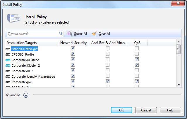
Select the specific QoS gateways on which to install the QoS Policy. QoS will enforce the QoS Policy on the directions specified in the interface properties of each selected gateway.
For further information, see Implementing the Rule Base.
Conclusion
You have now completed all the steps that were required to install the network described Introduction, and to define the Rule Base that will implement the required policy QoS policy.
As a result, you should have a much better understanding of how QoS policy can be implemented using QoS. It is strongly recommended however that you now spend some time and refer to Managing QoS for further information.
|
