Print Download PDF Send Feedback

Previous

Next

Network Management

In This Section:

Network Interfaces

ARP

DHCP Server

Hosts and DNS

IPv4 Static Routes

IPv6 Static Routes

Netflow Export

Performance Optimization

This chapter includes configuration procedures and examples for network management.

Network Interfaces

Gaia supports these network interface types:

Note - When you add, delete or make changes to interface IP addresses, it is possible that when you use the Get Topology option in SmartDashboard, the incorrect topology is shown. If this occurs, run cpstop and then cpstart in expert mode.

Interface Link Status

You can see the status of physical and logical interfaces by using the WebUI or the CLI.

To see interface status using the WebUI:

  1. In the navigation tree, select Network Management > Network Interfaces.
  2. Double-click an interface to see its parameters.

Link Status

Description

Grey (Down)

The physical interface is disabled (Down).

Red (no Link)

The physical interface is enabled (up), but Gaia cannot find a network connection.

Green (Up)

The physical interface is enabled (up) and connected to the network.

To see interface status using the CLI, run show interfaces all

Physical Interfaces

This section has configuration procedures and examples for defining different types of interfaces on a Gaia platform.

Gaia automatically identifies physical interfaces (NICs) installed on the computer. You cannot add or delete a physical interface using the WebUI or the CLI. You cannot add, change or remove physical interface cards while the Gaia computer is running.

To add or remove an interface card:

  1. Turn off the computer.
  2. Add, remove or replace the interface cards.
  3. Start the computer.

Gaia automatically identifies the new or changed physical interfaces and assigns an interface name. The physical interfaces show in the list in the WebUI.

Configuring Physical Interfaces - WebUI

This section includes procedures for changing physical interface parameters using the WebUI.

To configure a physical interface:

  1. In the navigation tree, select Network Management > Network Interfaces.
  2. Select an interface from the list and click Edit.
  3. Select the Enable option to set the interface status to UP.
  4. On the IPv4 tab, do one of these:
    • Select Obtain IPv4 address automatically to get the IP address from the DHCP server.
    • Enter the IP address and subnet mask in the applicable fields.
  5. On the IPv6 tab, do one of these:
    • Select Obtain IPv6 address automatically to get the IP address from the DHCP server.
    • Enter the IP address and mask length in the applicable fields.
  6. On the Ethernet tab, configure the link speed and duplex setting, and then do one of these:
    • Select Auto Negotiation to automatically configure the link speed and duplex setting.
    • Select a link speed and duplex setting from the list.
  7. Enter the hardware MAC address (if not automatically received from the NIC).

    Caution: Do not manually change the MAC address unless you are sure that it is incorrect or has changed. An incorrect MAC address can lead to a communication failure.

  8. Enter a different Maximum Transmission Unit (MTU) value (minimum value=68 - default=1500).

Configuring Physical Interfaces - CLI (interface)

Description

Configure physical interfaces

Syntax

set interface <IF> 
   ipv4-address <IP>
mask-length <Mask>
       subnet-mask <Mask>
   ipv6-address <IP> mask-length <Mask>
   ipv6-autoconfig <on | off>
   comments <Text>
   mac-addr <MAC>
   mtu <MTU setting>
   state <on | off>
   link-speed <Speed_Duplex>
   auto-negotiation <on | off>
 
show interfaces all

Parameters

interface

Configures a physical or virtual interface

ipv4-address
ipv6-address

Assigns the IPv4 or IPv6 address

ipv6-autoconfig

If on, automatically gets the IPv6 address from the DHCP

mask-length

Configures IPv4 or IPv6 subnet mask length using CIDR ( /xx) notation

subnet-mask

Configures IPv4 subnet mask using dotted decimal notation

comments

Adds free text comments to an interface definition

mac-addr

Configures the interface hardware MAC address

mtu

Configure the Maximum Transmission Unit size for an interface

state

Sets interfaces status to on (enabled) or off (disabled).

link-speed

Configures the interface link speed and duplex status

auto-
negotiation

Configures automatic negotiation of interface link speed and duplex settings - on (enabled) or off (disabled)


Parameter Values

<IP>

IPv4 or IPv6 address

<IF>

Interface name

<Mask>

Interface net mask in dotted decimal or CIDR (/xx) notation as applicable

<MAC>

Manually enter the applicable hardware address

<MTU Setting>

Integer greater or equal to 68 (Default = 1500)

<Speed_Duplex>

Enter the link speed in Mbps and duplex status using one of these values:

10M/half
10M/full
100M/half
100M/full
1000M/full
10000M/full


Examples

set interface eth2 ipv4-address 40.40.40.1 subnet-mask 255.255.255.0
 
set interface eth2 mtu 1500
set interface eth2 state on
set interface eth2 link-speed 1000M/full

Comments

There are some command options and parameters that you cannot do using the WebUI.

Important - After you add, configure, or delete features, run the save config command to keep settings after reboot.

Aliases

Interface aliases let you assign more than one IPv4 address to physical or virtual interfaces (bonds, bridges, VLANS and loopbacks). This section shows you how to configure an alias using the WebUI and the CLI.

Configuration using the WebUI

To configure an interface alias using the WebUI:

  1. In the navigation tree, select Network Management > Network Interfaces.
  2. Click Add > Alias. To change an existing alias interface, select an interface and then click Edit.
  3. In the Add (or Edit) Alias window, select Enable to set the alias interface status to UP.
  4. On the IPv4 tab, enter the IPv4 address and subnet mask.
  5. On the Alias tab, select the interface to which this alias is assigned.
    You cannot change the interface for an existing alias definition.

The new alias interface name is automatically created by adding a sequence number to the interface name. For example, the name of first alias added to eth1 is eth1:0. She second alias added is eth1:1, and so on.

To delete an interface alias:

  1. In the navigation tree, select Network Management > Network Interfaces.
  2. Select an interface alias and click Delete.
  3. When the confirmation message shows, click OK

Configuring Aliases - CLI (interface)

Description

Configure an alias to a physical interface.

Syntax

add interface <IF> alias <IP>/<Mask>
delete interface <IF> alias <Alias IF>

Parameter Values

<IP>

IPv4 address

<IF>

Interface name

<Mask>

IPv4 subnet mask length using CIDR ( /xx) notation

<Alias IF>

Interface alias name in the format <IF>:XX, where XX is the automatically assigned sequence number.


Examples

add interface eth1 alias 10.10.99.1/24
delete interface eth1 alias eth1:2

Comments

A new alias interface name is automatically created by adding a sequence number to the original interface name. For example, the name of first alias added to eth1 is eth1:0. She second alias added is eth1:1, and so on.

Important - After you add, configure, or delete features, run the save config command to keep settings after reboot.

VLAN Interfaces

You can configure virtual LAN (VLAN) interfaces on Ethernet interfaces. VLAN interfaces let you configure subnets with a secure private link to gateways and management servers using your existing topology. With VLAN interfaces, you can multiplex Ethernet traffic into many channels using one cable.

This section shows you how to configure VLAN interfaces using the WebUI and the CLI.

Configuring VLAN Interfaces - WebUI

To configure a VLAN interface using the WebUI:

  1. In the WebUI navigation tree, select Network Management > Network Interfaces.
  2. Click Add > VLAN. To change an existing VLAN interface, select an interface and then click Edit.
  3. In the Add (or Edit) VLAN window, select the Enable option to set the VLAN interface to UP.
  4. IPv4 and IPv6 tabs, enter the IP addresses and subnet information as necessary. You can optionally select the Obtain IP Address automatically option.
  5. On the VLAN tab, enter or select a VLAN ID (VLAN tag) between 2 and 4094.
  6. In the Member Of field, select the physical interface related to this VLAN.

Note - You cannot change the VLAN ID or physical interface for an existing VLAN interface. To change these parameters, delete the VLAN interface and then create a New VLAN interface.

Configuration Using the CLI

This section is a reference for the VLAN interface commands.

Description

Use these commands to configure bridge interfaces.

Syntax

add interface <IF> vlan <VLAN ID>
set interface <IF> <VLAN ID>
   ipv4-address <IP> mask-length <Length>|subnet-mask<Mask>
   ipv6-address <IP> mask-length <Length>
   ipv6-autoconfig
delete interface <IF> vlan <VLAN ID>

Parameters

interface

Configure an interface

ipv4-address

Assign an IPv4 address

ipv6-address

Assign an IPv6 address

ipv6-autoconfig

Automatically configure an IPv6 address

on

Enable automatic configuration

off

Disable automatic configuration


Values

Example

add interface vlan eth1
 
set interface eth1.99 ipv4-address 99.99.99.1 subnet-mask 255.255.255.0
 
set interface eth1.99 ipv6-address 209:99:1 mask-length 64 
 
delete interface eth1 vlan 99

Important - After you add, configure, or delete features, run the save config command to keep settings after reboot.

CLI Procedures

To add a new VLAN interface:

Run add interface <IF Name> vlan <VLAN ID>

Example:

add interface eth1 vlan 10

To add IP addresses to a VLAN interface:

Run:
set interface <IF Name>.<VLAN ID> ipv4-address <IPv4 Address> [ipv6-address <IPv6 Address>]

Examples:

set interface eth1.99 ipv4-address 99.99.99.1 subnet-mask 255.255.255.0
set interface eth1.99 ipv6-address 209:99:1 mask-length 64 

To delete a VLAN Interface:

Run:
delete interface <IF Name> vlan <VLAN ID>

Example:
delete interface eth1 vlan 10

Bond Interfaces (Link Aggregation)

Check Point security devices support Link Aggregation, a technology that joins multiple physical interfaces into one virtual interface, known as a bond interface. The bond interface gives fault tolerance and increases throughput by sharing the load among many interfaces. Check Point devices support the IEEE 802.3ad Link Aggregation Control Protocol (LCAP) for dynamic link aggregation.

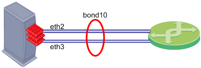
A bond interface (also known as a bonding group or bond) is identified by its Bond ID (for example: bond1) and is assigned an IP address. The physical interfaces included in the bond are called slaves and do not have IP addresses.

You can define bond interfaces using one of these functional strategies:

Configuring Bond Interfaces - WebUI

To configure a bond interface using the WebUI:

  1. Make sure that the slave interfaces do not have IP addresses.
  2. On the WebUI Network Interfaces page, click Enable.
  3. For a new bond interface, select Add > Bond. For an existing Bond interface, double-click the bond interface.
  4. Select the Enable option to activate the bond interface.
  5. On the IPv4 and IPv6 tabs (optional), enter the IP address information.
  6. On the Bond tab, select or enter a Bond Group name. This parameter is an integer between 1 and 1024.
  7. Select slave interfaces from the Available Interfaces list and then click Add.
  8. Select an Operation Mode (Round Robin is the default).
  9. On the Advanced tab, set the Monitor Interval to the frequency of requests to send to the monitor interface, to confirm that a slave interface is up. The valid range is 1-5000 ms and the default is 100 ms.
  10. Set the Down Delay and Up Delay to the time to wait after the monitor request, before an action is taken.
  11. Select the Primary Interface (for Active/Backup bonds only).
  12. Select the Transmit Hash Policy (XOR or 802.3ad). Set the algorithm for interface selection according to the specified TCP/IP layer. Valid values are layer2 (uses XOR of the physical interface MAC address) and layer3+4 (users upper layer protocol data).
  13. Select the LACP Rate. Set the Link Aggregation Control Protocol packet transmission rate. Valid values are slow (every 30 seconds) and fast (every 1 second).

Configuring Bond Interfaces - CLI

In the CLI, bond interfaces are known as bonding groups. Make sure the interfaces of the bond do not already have IP addresses.

Important: After you run a CLI command to add, configure, or delete an object, run the save config command to keep settings after reboot.

To create a bond interface with the CLI:

  1. Create the bond interface.
  2. Define the slave interfaces and set them to the UP State.
  3. Set the bond operating mode.
  4. Define other bond parameters: primary interface, media monitoring, delay rate.
Link Aggregation - CLI (bonding)

This section is a quick reference for Link Aggregation commands. The next sections include procedures for different tasks, including explanations of the configuration options.

Use these commands to configure link aggregation.

Syntax:

{add | delete} bonding group <bondID> interface <IFName>

set bonding [group <bondID>] [primary <IFName>] [mii-interval <ms>] [up-delay <ms> | down-delay <ms>] [mode {round-robin | active-backup | xor [xmit-hash-policy {layer2 | layer3+4}]| 8023AD [lacp-rate {slow | fast}]}]

show bonding group {<bondID> | groups}

Parameters

Parameter

Description

bondID

ID of bond, an integer between 1 and 1024

IFName

Name of interface to add to the bond

primary

Name of primary interface in the bond

mii-interval

Frequency that the system polls the Media Independent Interface (MII) to get status

up-delay
down-delay

Waiting time to confirm the interface status before taking the specified action (0-5000 ms, default = 200 ms)

mode

Bond operating mode

lacp-rate

Link Aggregation Control Protocol packet transmission rate:

  • slow - LACPDU packet sent every 30 seconds
  • fast - LACPDU packet sent every second

xmit-hash-policy

Algorithm for interface selected by TCP/IP layer

Example

set bonding group 666 20 eth2
show bonding groups

Output

Bonding Interface: 20
    Bond Configuration
        xmit_hash_policy Not configured
        down-delay 200
        primary Not configured
        mode round-robin
        up-delay 200
        mii-interval 100
        lacp_rate Not configured
        Bond Interfaces
            eth2
            eth3


Creating or Deleting a Bond Interface

To add a new bond interface:

add bonding group <bondID>

Example:

add bonding group 777

To delete a bond interface:

  1. Remove all interfaces from the bond.
  2. Run: delete bonding group <bondID>
Defining Interfaces

A bond interface typically contains between two and eight slave interfaces. This section shows how to add and remove a slave interface. The slave interface must not have IP addresses assigned to it.

To add a slave interface to a bond:

add bonding group <bondID> interface <IFName>

Example:

add bonding group 777 interface eth4

Note - Do not change the bond state manually. This is done automatically by the bonding driver.

To delete a slave interface from a bond:

delete bonding group <bondID> interface <IFName>

Example:

delete bonding group 777 interface eth4

Note - You must delete all non-primary slave interfaces before you remove the primary slave interface.

Defining the Bond Operating Mode

Define how interfaces are activated in a bond:

To define the bond operating mode:

set bonding group <BondID> mode <mode> [option]

Example:

set bonding group 777 mode xor xmit-hash-policy layer3+4
Defining the Primary Slave Interface

With the Active-Backup operating mode, the system automatically fails over to the primary slave interface, if available. If the primary interface is not available, the system fails over to a different slave interface. By default, the first slave interface that you define is the primary interface. You must define the slave interfaces and set the operating mode as Active-Backup before doing this procedure.

Note - You must delete all non-primary slave interfaces before you remove the primary slave interface.

To define the primary slave interface:

set bonding group <bondID> mode active-backup primary <IFName>

Example

add bonding group 777 interface eth4
set bonding group 777 mode active-backup primary eth4 
Defining the Media Monitoring Interval

This sets the frequency of requests sent to the Media Independent Interface (MII) to confirm that a slave interface is up. The valid range is 1-5000 ms. The default is 100 ms.

To configure the monitoring interval:

set bonding group <bondID> mii-interval <ms>

Example:

set bonding group 777 mii-interval 500

To disable monitoring:

set bonding group <bondID> mii-interval 0

Defining the UP and Down Delay Times

This parameter defines the waiting time, in milliseconds, to confirm the slave interface status before taking the specified action. Valid values are 0 to 5000 ms. The default is 200 ms.

To configure the UP and Down delay times:

set bonding group <bondID> down-delay <ms>
set bonding group <bondID> up-delay <ms>

Example:

set bonding group 777 down-delay 500
Making Sure that Link Aggregation is Working

To make sure that a Link Aggregation is working for a bond interface, run this command in expert mode:

cat /proc/net/bonding/<bondID>

Example with output:

cat /proc/net/bonding/bond666
Ethernet Channel Bonding Driver: v3.2.4 (January 28, 2008)
 
Bonding Mode: fault-tolerance (active-backup)
Primary Slave: None
Currently Active Slave: eth2
MII Status: up
MII Polling Interval (ms): 100
Up Delay (ms): 100
Down Delay (ms): 200
 
Slave Interface: eth2
MII Status: up
Link Failure Count: 2
Permanent HW addr: 00:50:56:94:11:de

Bridge Interfaces

Check Point security devices support bridge interfaces that implement native, Layer-2 bridging. Configuration of an interface as a bridge lets network administrators deploy security devices in a topology without reconfiguration of the IP routing scheme. This is an important advantage for large-scale, complex environments. Gaia does not support Spanning Tree Protocol (STP) bridges.

You configure Ethernet interfaces (including aggregated interfaces) on your Check Point security device to work like ports on a physical bridge.

Note - You cannot configure as a bridge interface an interface that you configure as a bond slave.

The bridge interfaces send traffic with Layer-2 addressing. On the same device, you can configure some interfaces as bridge interfaces, while other interfaces work as layer-3 interfaces. Traffic between bridge interfaces is inspected at Layer-2. Traffic between two Layer-3 interfaces, or between a bridge interface and a Layer-3 interface is inspected at Layer-3.

This section shows you how to configure bridge interfaces using the WebUI and the CLI.

Configuring Bridge Interfaces - WebUI

To configure a bridge interface in the WebUI:

  1. In the WebUI navigation tree, select Network Interfaces.
  2. Click Add > Bridge, or select an interface and click Edit.

    The Add (or Edit) Bridge window opens.

  3. On the Bridge tab, enter or select a Bridge Group ID (unique integer between 1 and 1024).
  4. Select the interfaces from the Available Interfaces list and then click Add.
  5. Click the IPv4 or IPv6 tabs, and then enter the IP addresses and subnet.

    Or click Obtain IP Address automatically.

  6. Click OK.

Bridging group commands

This is a quick reference for bridge interface commands.

Description - Use these commands to configure bridge interfaces.

Syntax

add bridging group <Group ID> [interface <interface>]
delete bridging group <Group ID> interface <interface>
show bridging group <Group ID>

Parameters

Parameter

Description

<Group ID>

ID of bridging group

<interface>

Interface name

Example - add bridging group 56 interface eth1

Important - After you add, configure, or delete features, run the save config command to keep settings after reboot.

Configuring Bridge Mode with the CLI

Bridge interfaces are known as Bridging Groups in Gaia clish commands. You can assign an IPv4 or IPv6 address to a bridge interface.

To see the interfaces of an existing bridge:

show bridging group <Group ID>

Where Group ID is the unique identifier of the bridge, an integer between 0 and 1024

To create a new bridging group:

add bridging group <Group ID> [interface <Bridge Interface Name>]

To add an interface to the bridging group:

add bridging group <Group ID> interface <Physical interface Name>

Run this command one time for each physical interface.

To remove an interface from the bridging group:

delete bridging group <Group ID> interface <Physical interface Name>

Run this command one time for each physical interface.

To delete a bridging group:

delete bridging group <Group ID>

To add or change a bridge interface IP address:

Examples:

add bridging group 56 interface eth1
set interface br1 ipv6-address 3000:40::1 mask-length 64

Important - After you add, configure, or delete features, run the save config command to keep settings after reboot.

Loopback Interfaces

You can define a virtual loopback interface by assigning an IPv4 or IPv6 address to the lo (local) interface. This can be useful for testing purposes or as a proxy interface for an unnumbered interface. This section shows you how to configure a loopback interface using the WebUI and the CLI.

Configuring Loopback Interfaces - WebUI

To configure a loopback interface using the WebUI:

  1. In the navigation tree, select Interface Management > Network Interfaces.
  2. Click Add > Alias. To change an existing loopback interface, select an interface and then click Edit.
  3. In the Add (or Edit) window, select Enable to set the loopback interface status to UP.
  4. On the IPv4 tab, enter the IPv4 address and subnet mask.
  5. On the IPv6 tab, enter the IPv6 address and mask length.

The new loopback interface name is automatically created with the addition of a sequence number to the string 'loop'. For example, the name of first loopback interface is loop00. The second loopback interface is loop01, and so on.

To delete an interface alias:

  1. In the navigation tree, select Network Management > Network Interfaces.
  2. Select an alias interface and click Delete.
  3. When the confirmation message shows, click OK

Configuring Loopback Interfaces - CLI (interface)

Description

Configure loopback interfaces

Syntax

add interface lo loopback <IP>/<Mask>
delete interface lo loopback <IF>

Parameters and Values

loopback

Configures a loopback interface.

lo

You must use the lo (local interface) keyword to define a loopback interface.

<IP>

IPv4 or IPv6 address.

<Mask>

IPv4 subnet mask or IPv6 mask length using CIDR ( /xx) notation.

<IF>

Loopback interface name (loopXX)


Examples

add interface lo loopback 10.10.99.1/24
add interface lo loopback 2010:10:99::1/64
delete interface lo loopback loop01

Comments

When you create a new loopback interface, Gaia automatically assigns a name in the format loopXX, where XX is a sequence number starting from 00.

Important: After using CLI commands to add, configure or delete features, you must run the save config command. This makes sure that the new configuration settings remain after reboot.

VPN Tunnel Interfaces

Virtual Tunnel Interface. A virtual interface that is a member of an existing, Route-Based, VPN tunnel. Each peer Security Gateway has one VTI that connects to the tunnel.

The VPN tunnel and its properties are defined by the VPN community that contains the two gateways. You must define the VPN community and its member Security Gateways before you can create a VTI. To learn more about Route Based VPN, see Route Based VPN in the R77 VPN Administration Guide.

The procedure for configuring a VTI includes these steps:

  1. Make sure that the VPN Software Blade is enabled and licensed on the applicable Security Gateways.
  2. Create and configure the Security Gateways.
  3. Define a VPN community in SmartDashboard that includes the two peer Security Gateways.
  4. Make Route Based VPN the default option. Do this procedure one time for each Security Management Server.
  5. Define the VTI using the WebUI or CLI.
  6. Define Route Based VPN Rules.
  7. Save the configuration and install the policy.

Defining the VPN Community

You must define the VPN Community and add the member Security Gateways to it before you configure a VPN Tunnel Interface. This section includes the basic procedure for defining a Site to Site VPN Community. To learn more about VPN communities and their definition procedures, see the R77 VPN Administration Guide.

To define a VPN Community for Site to Site VPN:

  1. In SmartDashboard, click the VPN Communities tab in the navigation tree.
  2. Right-click Site To Site and select New Site To Site > Meshed or Star.
  3. In the Community Properties window General tab, enter the VPN community name.
  4. Select Accept all encrypted traffic.

    This option automatically adds a rule to encrypt all traffic between gateways in a VPN community.

  5. On the Participating Gateways tab, select member gateways from the list.

    For star communities, use the Center Gateways and Satellite Gateways tabs to do this.

  6. Configure other community parameters as necessary.
  7. Save your configuration to the database.

Making Route Based VPN the Default Option

When Domain Based VPN and Route Based VPN are defined for a Security Gateway, Domain Based VPN is active by default. You must do two short procedures to make sure that Route Based VPN is always active.

The first procedure defines an empty encryption domain group for your peer gateways. You do this step one time for each Security Management Server. The second step is to make Route Based VPN the default option for all Security Gateways.

To Define an empty group:

  1. In the SmartDashboard navigation tree, right-click Groups and then select Groups > Simple Group.
  2. In the Group Properties window, enter a group name in the applicable field.
    Do not add members to this group.

To make Route Based VPN the default choice:

  1. In SmartDashboard, double-click the applicable Security Gateway.
  2. In the Gateway window, click Topology.
  3. In the VPN Domain section, select Manually define and then select the empty group.

Do these steps for each Security Gateway.

Configuring VPN Tunnel Interfaces

You can configure the VPN Tunnel Interfaces using Gaia WebUI or CLI.

Configuring VPN Tunnel Interfaces - WebUI

This section shows you how to configure a VPN Tunnel interface using the WebUI.

To configure a VPN Tunnel Interface:

  1. In the Gaia WebUI, select Network Management > Network Interfaces.
  2. Click Add > VPN Tunnel to create a new interface.
    Double-click an existing VTI to change its parameters.
  3. In the Add/Edit window, configure these parameters:
    • VPN Tunnel ID - Unique tunnel name (integer from 1 to 99)
      Gaia automatically adds the prefix 'vpnt' to the tunnel name.
    • Remote Peer Name- Remote peer name as defined in the VPN community. You must define the two peers in the VPN community before you can define the VTI. The Peer ID is an alpha-numeric character string.
    • VPN Tunnel Type - Select Numbered or Unnumbered.
    • Local Address - Defines the local peer IPv4 address (numbered VTI only).
    • Remote Address - Defines the remote peer IPv4 address (numbered VTI only).
    • Physical Device - Local peer interface name (unnumbered VTI only).
Configuring VPN Tunnel Interfaces - CLI (vpn tunnel)

This section shows the CLI commands used to add or delete VPN Tunnel Interfaces.

Description

Add or delete a VPN Tunnel Interface (VTI)

Syntax

add vpn tunnel <Tunnel ID>

type numbered local <Local IP> remote <Remote IP> peer <Peer IP>

type unnumbered peer <Peer ID> dev <IF>


delete vpn tunnel <Tunnel ID>

Parameters

type numbered

Defines a numbered VTI that uses a specified, static IPv4 addresses for local and remote connections.

type unnumbered

Defines an unnumbered VTI that uses the interface and the remote peer name to get addresses.

local

Defines the local peer IPv4 address (numbered VTI only).

remote

Defines the remote peer IPv4 address (numbered VTI only).

peer

Remote peer name as defined in the VPN community. You must define the two peers in the VPN community before you can define the VTI. The Peer ID is an alpha-numeric character string.

dev

Defines the interface (unnumbered VTI only)


Parameter
Values

<Tunnel ID>

Unique tunnel name (integer from 1 to 99)
Gaia automatically adds the prefix 'vpnt' to the tunnel name

Example: vnpt10

<Local IP>

Local peer IPv4 address (numbered VTI only) in dotted decimal format

<remote IP>

Remote peer IPv4 address (numbered VTI only) in dotted decimal format

<Peer ID>

Remote peer name as defined in the VPN community. You must define the two peers in the VPN community before you can define the VTI. The Peer ID is an alpha-numeric character string.

<IF>

Local peer interface name (unnumbered VTI only)


Example

add vpn tunnel 20 type numbered local 10.10.10.1 remote 20.20.20.1 peer MyPeer

add vpn tunnel 10 type unnumbered peer MyPeer dev eth1
delete vpn tunnel 10

Important - After you add, configure, or delete features, run the save config command to keep settings after reboot.

CLI Configuration Procedures for VPN Tunnel Interfaces

To add a numbered VPN Tunnel Interface:

Run:

add vpn tunnel <Tunnel ID> type numbered local <Local IP> remote <Remote IP>
peer <Peer ID>

To add an unnumbered VPN Tunnel Interface:

Run:

add vpn tunnel <Tunnel ID> type unnumbered local peer <Peer ID>

To Delete a VPN Tunnel Interface

Run:

delete vpn tunnel <Tunnel ID>

Defining VPN Rules

To make sure that your security rules work correctly with Route Based VPN traffic, you must add directional matching conditions and allow OSPF traffic. This section includes procedures for configuring security rules to do this.

Defining Directional Matching VPN Rules

This section contains the procedure for defining directional matching rules. Directional matching is necessary for Route Based VPN when a VPN community is included in the VPN column in the rule. This is because without bi-directional matching, the rule only applies to connections between a community and an encryption domain (Domain Based Routing).

Name

Source

Destination

VPN

Service

Action

VPN Tunnel

Any

Any

MyIntranet

Any

accept

The directional rule must contain these directional matching conditions:

MyIntranet is the name of a VPN Community. Internal_Clear refers to all traffic from IP addresses to and from the specified VPN community.

Name

Source

Destination

VPN

Service

Action

VPN Tunnel

Any

Any

MyIntranet > MyIntranet
MyIntranet > Internal_Clear
Internal_Clear > MyIntranet

Any

accept

Note - It is not necessary to define bidirectional matching rules if the VPN column contains the Any value.

To enable VPN directional matching:

  1. In SmartDashboard, go to Policy > Global Properties > VPN > Advanced.
  2. Select the Enable VPN Directional Match in VPN Column option.
  3. In SmartDashboard, double-click each member gateway and go to the Topology page.
    1. Click Get > Interfaces with Topology to update the topology to include the newly-defined VTIs.
    2. Click Accept.

To define a VPN directional matching rule:

  1. Double-click the VPN cell in the applicable rule.
  2. In the VPN Match Conditions window, select Match traffic in this direction only.
  3. Click Add to define sets of matching conditions.
  4. In the Direction VPN Match Condition window, select the source and destination matching conditions.

    Do this step for each set of matching conditions.

Defining Rules to Allow OSPF Traffic

One advantage of Route Based VPN is the fact that you can use dynamic routing protocols to distribute routing information between Security Gateways. The OSPF (Open Shortest Path First) protocol is commonly used with VTIs. This section shows you how to allow OSPF traffic in a VPN community.

To learn about configuring OSPF, see the R77 Gaia Advanced Routing Administration Guide.

To Allow OSPF traffic for a VPN Community:

  1. Using the Gaia WebUI or CLI, add the applicable VPN Tunnel Interfaces to the OSPF configuration page.
  2. In SmartDashboard, add a rule that allows traffic to the VPN community (or all communities) using the OSPF service.

Name

Source

Destination

VPN

Service

Action

Allow OSPF

Any

Any

MyIntranet

ospf

accept

Completing the VTI Configuration

You must save your configuration to the database and install policies to the Security Gateways before the VPN can be fully functional.

To complete the VTI configuration:

  1. Save the configuration to the database.
  2. Install the policy to the gateways.
  3. Make sure that the VTI tunnel and the rules are working correctly.

CLI Reference (interface)

This section summarizes the CLI interface command and its parameters.

Description

Add, delete and configure interface properties.

Syntax

add interface <IF>

6in4 <Tunnel ID> remote <IP> ttl <Time>

6to4 <Tunnel ID> ttl <Time>

alias <IP>

loopback <IP>

vlan <VLAN ID>

delete interface <IF>

6in4 <Tunnel ID>

6to4 <Tunnel ID>

alias <IP>

ipv4-address <IP>

ipv6-address <IP>

ipv6-autoconfig

loopback <IP>

vlan <VLAN ID>

set interface <IF>

ipv4-address <IP>
mask-length <Mask>

subnet-mask <Mask>

ipv6-address <IP> mask-length <Mask>

ipv6-autoconfig <on | off>

comments <Text>

mac-addr <MAC>

mtu <MTU setting>

state <on | off>

link-speed <Speed Duplex>

auto-negotiation <on | off>

Parameters

interface

Configures a physical or virtual interface

6in4

Configures a 6in4 tunnel for IPv6 traffic over an IPv4 network

6to4

Configures a 6to4 tunnel for IPv6 traffic over an IPv4 network

remote

Sets the remote IP address for a 6in4 or 6to4 tunnel

ttl

Sets the time-to-live value for a 6in4 or 6to4 tunnel

alias

Assigns more than one IP addresses to a physical interface
(IPv4 only)

loopback

Assigns an IP address to a logical loopback interface. This can be useful as a proxy for an unnumbered interface.

vlan

Assigns a VLAN tag to an existing physical interface to create a logical subnet.

ipv4-address
ipv6-address

Assigns the IPv4 or IPv6 address

ipv6-autoconfig

If on, automatically gets the IPv6 address from the DHCP

mask-length

Configures IPv4 or IPv6 subnet mask length using CIDR ( /xx) notation

subnet-mask

Configures IPv4 subnet mask using dotted decimal notation

comments

Adds free text comments to an interface definition

mac-addr

Configures the interface hardware MAC address

mtu

Configure the Maximum Transmission Unit size for an interface

state

Sets interfaces status to on (enabled) or off (disabled).

link-speed

Configures the interface link speed and duplex status

auto-
negotiation

Configures automatic negotiation of interface link speed and duplex settings - on (enabled) or off (disabled)


Parameter Values

<Tunnel ID>

Unique tunnel identifier (Integer in the range 2-4094)

<IP>

IPv4 or IPv6 address

<IF>

Interface name

<Time>

TTL time in seconds in the range 0-255 (default = 0)

<VLAN ID>

Integer in the range 2-4094

<Mask>

Interface net mask in dotted decimal or CIDR (/xx) notation as applicable

<MAC>

Manually enter the applicable hardware address

<MTU Setting>

Integer greater or equal to 68 (Default = 1500)

<Speed>

Enter the link speed in Mbps and duplex status using one of these values:

10M/half
10M/full
100M/half
100M/full
1000M/full

10000M/full


Examples

See the interface configuration section.

Comments

There are some command options and parameters that you cannot do using the WebUI.

ARP

The Address Resolution Protocol (ARP) allows a host to find the physical address of a target host on the same physical network using only the target’s IP address. ARP is a low-level protocol that hides the underlying network physical addressing and permits assignment of an arbitrary IP address to every machine. ARP is considered part of the physical network system and not as part of the Internet protocols.

Configuring ARP- WebUI

To show dynamic ARP entries

  1. In the WebUI, go to the Network Management > ARP page.
  2. Click the Monitoring tab.

To show static ARP entries

  1. In the WebUI, go to the Network Management > ARP page.
  2. Click the Configuration tab.

To change Static and dynamic ARP parameters

  1. In the WebUI, go to the Network Management > ARP page.
  2. In the Configuration tab, ARP Table Settings section:
    1. Enter the Maximum Entries. This is the maximum number of entries in the ARP cache.

      Default: 1024, Range: 1024-16384

      Note – Make sure to configure a value large enough to accommodate at least 100 dynamic entries, in addition to the maximum number of static entries.

    2. Enter the Validity Timeout. This is the time, in seconds, to keep resolved dynamic ARP entries. If the entry is not referred to and is not used by traffic before the time elapses, it is deleted. Otherwise, a request will be sent to verify the MAC address.

      Default: 60 (seconds), Range: 60-86400 (24 hours)

To add a static ARP entry

  1. In the WebUI, go to the Network Management > ARP page.
  2. In the Configuration tab, Static ARP Entries section, click Add.
  3. Enter the IP Address of the static ARP entry and the MAC Address used when forwarding packets to the IP address.
  4. Click OK.

To delete a Static ARP entry

  1. In the WebUI, go to the Network Management > ARP page.
  2. In the Configuration tab, Static ARP Entries section, select a Static ARP entry
  3. Click Remove.

To flush all dynamic ARP entries

  1. In the WebUI, go to the Network Management > ARP page.
  2. In the Monitoring tab, click Flush All.

Configuring ARP - CLI (arp)

Description

Commands to configure the Address Resolution Protocol (ARP)

Syntax

To add a static arp entry

add arp static ipv4-address VALUE macaddress VALUE
 

To delete static and dynamic arp entries

delete arp dynamic all
delete arp static ipv4-address VALUE
 

To set arp parameters

set arp table validity-timeout VALUE
set arp table cache-size VALUE
 

To show arp parameters

show arp dynamic all
show arp static all
show arp table validity-timeout
show arp table cache-size


Parameters

static

Configured static arp entries

dynamic 

Configured dynamic arp entries

ipv4-address 

IP Address of a static ARP entry. Range: Dotted-quad ([0-255].[0-255].[0-255].[0-255]).

Default: No Default

macaddress 

The hardware address used when forwarding packets to the given IP address. Range: Six hexadecimal octets separated by colon.

Default: No Default

table validity-timeout

This is the time, in seconds, to keep resolved dynamic ARP entries. If the entry is not referred to and is not used by traffic before the time elapses, it is deleted. Otherwise, a request will be sent to verify the MAC address.

Default: 60 (seconds), Range: 60-86400 (24 hours)

table cache-size

This is the maximum number of entries in the ARP cache.

Default: 1024, Range: 1024-16384

Note – Make sure to configure a value large enough to accommodate at least 100 dynamic entries, in addition to the maximum number of static entries.


Important - After you add, configure, or delete features, run the save config command to keep settings after reboot.

DHCP Server

You can configure the Gaia device to be a Dynamic Host Configuration Protocol (DHCP) server. The DHCP server give IP addresses and other network parameters to network hosts. DHCP makes it unnecessary to configure each host manually, and therefore reduces configuration errors.

You configure DHCP server subnets on the Gaia device interfaces. A DHCP subnet allocates these network parameters to hosts behind the Gaia interface:

This is the general workflow for allocating DHCP parameters to hosts (for the details, see the next section):

  1. To define a DHCP subnet on a Gaia device interface:
    1. Enable DHCP on the Gaia network interface.
    2. Define the network IPv4 address of the subnet on the interface.
    3. Define an IPv4 address pool.
    4. Optional: Define routing and DNS parameters for hosts.
  2. Define additional DHCP subnets on other Gaia interfaces, as needed.
  3. Enable the DHCP server process.
  4. Configure the network hosts to use the DHCP server.

Configuring a DHCP Server- WebUI

To allocate DHCP parameters to hosts

  1. In the tree view, click Network Management > DHCP Server.
  2. In the DHCP Server Subnet Configuration section, click Add.

    The Add DHCP window opens. You now define a DHCP subnet on an Ethernet interface of the Gaia device. Hosts behind the Gaia interface get IPv4 addresses from address pools in the subnet.

  3. Select Enable DHCP to enable DHCP for the subnet.
  4. In the Subnet tab, enter the Network IP Address of the interface. Click Get from interface to do this automatically.
  5. Enter the Subnet mask.
  6. In the Address Pool section, click Add and define the range of IPv4 addresses that the server assigns to hosts.
  7. Optional: Define a Default Lease in seconds, for host IPv4 addresses. This applies only if clients do not request a unique lease time. If you do not enter a value, the configuration default is 43,200 seconds.
  8. Optional: Define a Maximum Lease in seconds, for host IPv4 addresses. This is the longest lease available. If you do not enter a value, the configuration default is 86,400 seconds.
  9. Optional: Click the Routing & DNS tab to define routing and DNS parameters for hosts:
    • Default Gateway. The IPv4 address of the default gateway for the network hosts
    • Domain Name. The domain name of the network hosts. For example, example.com.
    • Primary DNS Server. The DNS server that the network hosts use to resolve hostnames.
    • Secondary DNS Server. The DNS server that the network hosts use to resolve hostnames if the primary server does not respond.
    • Tertiary DNS Server. The DNS server that the network hosts use to resolve hostnames if the primary and secondary servers do not respond.
  10. Click OK.
  11. Optional: Define DHCP subnets on other Gaia interfaces, as needed.
  12. In the main DHCP Server page, select Enable DHCP Server.
  13. Click Apply.

The DHCP server on Gaia is now configured and enabled.

You can now configure your network hosts to get their network parameters from the DHCP server on Gaia.

Configuring a DHCP Server - CLI (dhcp)

Description

DHCP Server commands allow you to configure the Gaia device as DHCP server for network hosts.

Syntax

To create DHCP Server subnets:

add dhcp server subnet VALUE 
	netmask VALUE
	include-ip-pool start VALUE end VALUE
	exclude-ip-pool start VALUE end VALUE


To change DHCP Server subnet configurations:

set dhcp server subnet VALUE 
	enable
	disable
	include-ip-pool VALUE enable
	include-ip-pool VALUE disable
	exclude-ip-pool VALUE enable
	exclude-ip-pool VALUE disable
	default-lease VALUE
	max-lease VALUE
	default-gateway VALUE
	domain VALUE
	dns VALUE


To delete DHCP Server subnets:

delete dhcp server subnet VALUE 
	exclude-ip-pool VALUE
	include-ip-pool VALUE


To enable or disable the DHCP Server process:

set dhcp server 
	disable
	enable


To view DHCP Server configurations

show dhcp server 
	all
	status
	subnet VALUE ip-pools
	subnets

Parameters

Parameter

Description

subnet VALUE

The IPv4 address of the DHCP subnet on an Ethernet interface of the Gaia device. Hosts behind the Gaia interface get IPv4 addresses from address pools in the subnet. For example, 192.0.2.0

netmask VALUE

The IPv4 subnet mask in CIDR notation. For example,
24

start VALUE

The IPv4 address that starts the allocated IP Pool range. For example 192.0.2.20

end VALUE

The IPv4 address that ends the allocated IP Pool range. For example 192.0.2.90

include-ip-pool VALUE

The range of IPv4 addresses to include in the IP pool. For example 192.0.2.20-192.0.2.90

exclude-ip-pool VALUE

The range of IPv4 addresses to exclude from the IP pool. For example: 192.0.2.155-192.0.2.254

enable

Enable the DHCP Server subnet, or the DHCP Server process (depending on the context).

disable

Disable the DHCP Server subnet, or the DHCP Server process (depending on the context).

default-lease VALUE

The default lease in seconds, for host IPv4 addresses. Applies only if clients do not request a unique lease time. If you do not enter a value, the default is 43,200 seconds.

max-lease VALUE

The maximum lease in seconds, for host IPv4 addresses. This is the longest lease available. If you do not enter a value, the configuration default is 86,400 seconds.

default-gateway VALUE

The IPv4 address of the default gateway for the network hosts

domain VALUE

The domain name of the network hosts. For example, example.com.

dns VALUE

The DNS servers that the network hosts will use to resolve hostnames. Optionally, specify a primary, secondary and tertiary server in the order of precedence. For example
192.0.2.101, 192.0.2.102, 192.0.2.103

all

All DHCP server configuration settings.

subnets

DHCP Server subnet configuration settings.

subnet VALUE ip-pools

The IP pools in the DHCP Server subnet, and their status: Enabled or Disabled.

status

The status of the DHCP Server process: Enabled or disabled.


Example

gw-9403be> show dhcp server all

Output

DHCP Server Enabled
DHCP-Subnet 192.0.2.0
    State           Enabled
    Net-Mask        24
    Maximum-Lease   86400
    Default-Lease   43200
    Domain          example.com
    Default Gateway 192.0.2.103
    DNS             192.0.2.101, 192.0.2.102, 192.0.2.103
    Pools (Include List)
        192.0.2.20-192.0.2.90           : enabled
        192.0.2.120-192.0.2.150         : disabled
    Pools (Exclude List)
        192.0.2.155-192.0.2.254         : enabled
DHCP-Subnet 192.0.2.155
    State           Disabled
    Net-Mask        24
    Maximum-Lease   86400
    Default-Lease   43200
    Pools (Include List)
        192.0.2.10-192.0.2.99           : enabled
DHCP-Subnet 192.0.2.200
    State           Disabled
    Net-Mask        24
    Maximum-Lease   86400
    Default-Lease   43200


Hosts and DNS

Host Name

You set the host name (system name) during initial configuration. You can change the name.

Configuring Host Name - WebUI

To show the host name

The host name is in the header of the WebUI.

To change the host name

  1. Open the Network Management > Host and DNS page.
  2. In the System Name section, enter the
    • Host Name. The network name of the Gaia device.
    • Domain Name (optional). For example, example.com.

Configuring Host Name - CLI (hostname)

Description

Use this group of commands to configure the host name of your platform.

Syntax

set hostname VALUE
show hostname

Host Addresses

You should add host addresses for systems that will communicate frequently with the system. You can:

Configuring Hosts- WebUI

To add a static host entry

  1. Go to the Network Management > Hosts and DNS page.
  2. In the Hosts section, click Add.
  3. Enter the
    • Host Name. Must include only alphanumeric characters, dashes ('-'), and periods ('.'). Periods must be followed by a letter or a digit. The name may not end in a dash or a period. There is no default value.
    • IPv4 address
    • IPv6 address

To edit a static host entry

  1. Go to the Network Management > Hosts and DNS page.
  2. In the Hosts section, select a host and click Edit.
  3. Edit the
    • Host Name
    • IPv4 address
    • IPv6 address

To delete a static host entry

  1. Go to the Network Management > Hosts and DNS page.
  2. In the Hosts section, select a host and click Delete.

Configuring Hosts - CLI (host)

Description

Add, edit, delete and show the name and addresses for hosts that will communicate frequently with the system

Syntax

To add a host name and address:

add host name VALUE ipv4-address VALUE
add host name VALUE ipv6-address VALUE

To edit the name and IPv4 or IPv6 address of a host:

set host name VALUE ipv4-address VALUE
set host name VALUE ipv6-address VALUE

To delete a host name and address:

delete host name VALUE ipv4
delete host name VALUE ipv6

To show an IPv4 or IPv6 host address:

show host name VALUE ipv4
show host name VALUE ipv6

To show all IPv4 or IPv6 hosts:

show host names ipv4
show host names ipv6
 

Parameters

Parameter

Description

name VALUE

The name of a static host. Must include only alphanumeric characters, dashes ('-'), and periods ('.'). Periods must be followed by a letter or a digit. The name may not end in a dash or a period. There is no default value.

ipv4-address VALUE

The IPv4 address of the host

ipv6-address VALUE

The IPv6 address of the host


Domain Name Service (DNS)

Gaia uses the Domain Name Service (DNS) to translate host names into IP addresses. To enable DNS lookups, you must enter the primary DNS server for your system. You can also enter secondary and tertiary DNS servers. When the system resolves host names, it consults the primary name server. If a failure or time-out occurs, the system consults the secondary name server, and if necessary, the tertiary.

You can also define a DNS Suffix, which is a search for host-name lookup.

Configuring DNS - WebUI

To configure the DNS Server for the Gaia computer:

  1. In the WebUI, go to the Network Management > Hosts and DNS page.
  2. In the System Name section, enter the Domain Name. For example, example.com.
  3. In the DNS Section, enter the:
    1. DNS Suffix. The name that is put at the end of all DNS searches if they fail. By default, it should be the local domain name.

      A valid domain name suffix is made up of subdomain strings separated by periods. Subdomain strings must begin with an alphabetic letter and may consist only of alphanumeric characters and hyphens. The domain name syntax is described in RFC 1035 (modified slightly in RFC 1123). Note: Domain names that are also valid numeric IP addresses, for example 10.19.76.100, though syntactically correct, are not allowed.

      For example, if you set the DNS Suffix to example.com and try to ping some host foo (by running ping foo), and foo cannot be resolved, then the resolving computer will try to resolve foo.example.com.
    2. IPv4 address or IPv6 of the Primary DNS Server. The server to use when resolving hostnames. This should be a host running a DNS server.
    3. (Optional) IPv4 or IPv6 address of the Secondary DNS Server. The server to use when resolving hostnames if the primary server does not respond. This should be a host running a DNS server.
    4. (Optional) IPv4 or IPv6 address of the Tertiary DNS Server. The server to use when resolving hostnames if the primary and secondary servers do not respond. This should be a host running a DNS server.

Configuring DNS - CLI (dns)

Description

Configure, show and delete the DNS servers and the DNS suffix for the Gaia computer.

Syntax

To configure the DNS servers and the DNS suffix for the Gaia computer:

set dns primary VALUE
set dns secondary VALUE
set dns tertiary VALUE
set dns suffix VALUE
 

To show the DNS servers and the DNS suffix for the Gaia computer:

show dns primary
show dns secondary
show dns tertiary
show dns suffix
 

To delete the DNS servers and the DNS suffix for the Gaia computer:

delete dns primary
delete dns secondary
delete dns tertiary
delete dns suffix
 

Parameters

primary VALUE

The server to use when resolving hostnames. This should be a host running a DNS server. An IPv4 or IPv6 address

secondary VALUE

The server to use when resolving hostnames if the primary server does not respond. This should be a host running a DNS server. An IPv4 or IPv6 address

tertiary VALUE

The server to use when resolving hostnames if the primary and secondary servers do not respond. This should be a host running a DNS server. An IPv4 or IPv6 address

suffix VALUE

The name that is put at the end of all DNS searches if they fail. By default, it should be the local domain name.

A valid domain name suffix is made up of subdomain strings separated by periods. Subdomain strings must begin with an alphabetic letter and may consist only of alphanumeric characters and hyphens. The domain name syntax is described in RFC 1035 (modified slightly in RFC 1123). Note: Domain names that are also valid numeric IP addresses, for example 10.19.76.100, though syntactically correct, are not allowed.

For example, if you set the DNS Suffix to example.com and try to ping some host foo (by running ping foo), and foo cannot be resolved, then the resolving computer will try to resolve foo.example.com.


IPv4 Static Routes

A static route defines the destination and one or more paths (next hops) to get to that destination. You define static routes manually using the WebUI or the set static-route command from the CLI.

Static routes let you add paths to destinations that are unknown by dynamic routing protocols. You can define multiple paths (next hops) to a destination and define priorities for selecting a path. Static routes are also useful for defining the default route.

Static route definitions include these parameters:

Configuring IPv4 Static Routes - WebUI

You can configure static routes one at a time or use the Batch Mode to configure many routes simultaneously.

To configure one static route at a time:

  1. In the WebUI navigation tree, select IPv4 Static Routes.
  2. In the IPv4 Static Routes pane, click Add
    or
    Select a route and click Edit to change an existing route.
  3. In the Add (or Edit) Destination Route window, enter the IPv4 address and subnet mask.
  4. Select the Next Hop Type.
    • Normal - Accepts and sends packets to the specified destination.
    • Reject - Drops packets and sends an error message to the traffic source.
    • Black Hole - Drops packets, but does not send an error message.
  5. Click Add gateway or double-click an existing gateway.
  6. For new interfaces only, select an interface type.
    • Normal - Identifies the destination gateway by its IP address.
    • Network Interface - Identifies the next hop gateway by the interface that connects to it. Use this option only if the next hop gateway has an unnumbered interface. This option is known as a logical interface in the CLI.
  7. Optional: Select Local Scope. Defines a static route with a link-local scope. Use this setting on a cluster member when the ClusterXL Virtual IP address is in a different subnet than the physical interface address. This allows the cluster member to accept static routes on the subnet of the Cluster Virtual address.
  8. Optional: Select Ping to send periodic ICMP packets to the route destination.

    This action makes sure that the connection is alive. If no answer is returned, the route is deleted from the routing table.

  9. Optional: Enter or select a Rank.

    This a route priority value to use when there are many routes to a destination that use different routing protocols. The route with the lowest rank value is selected. Default = 0.

  10. In the Add (or Edit) Interface gateway window, enter the IP address or interface name.
  11. Select a Priority between 1 and 8. The priority sets the order for selecting the next hop among many gateways. 1 (default) is the highest priority and 8 is the lowest. This parameter is required.

Configuring Many Static Routes at Once

You can use the batch mode to configure multiple static routes in one step.

Note - You cannot configure a network (logical) interface using this option.

To add many static routes at once:

  1. In the WebUI navigation tree, select Static Routes.
  2. In the Static Routes pane, click Add Multiple Static Routes.
  3. In the Add Multiple Routes window, select the Next Hop Type.
    • Normal - Accepts and sends packets to the specified destination
    • Reject - Drops packets and sends an error message to the traffic source
    • Black Hole - Drops packets, but does not send an error message
  4. Add the routes in the text box, using this syntax:

    <Destination IP>/<Mask length> <Next Hop IP> [<Comment>]

    default - Use this as an alternative to the default route IP address

    Destination IP - Destination IP address using dotted decimal notation

    Mask length - Net mask using slash (/xx) notation

    Next Hop IP - Next hop gateway IP address using dotted decimal notation

    Comment - Optional free text comment

    Examples:

    default 192.0.2.100 192.0.2.1 "Default Route"

    192.0.2.200 192.0.2.18

  5. Click Apply.

    The newly configured more static routes show in the list of Static Routes in the Static Routes page.

Note - The text box shows entries that contain errors with messages at the top of the page.

  1. Correct errors and reload the affected routes.
  2. Click the Monitoring tab to make sure that the routes are configured correctly.

Configuring Static Routes - CLI (static-route)

You only use the set operation with the static-route command, even when adding or deleting a static route.

Description

Add, change or delete an IPv4 static route.

Syntax

set static-route <Destination>

nexthop gateway address <GW IP> [priority <P Value>] on|off

nexthop gateway logical <GW IF> [priority <P Value>] on|off

nexthop blackhole

nexthop reject

scopelocal on

set static-route <Destination> off

set static-route <Destination> rank <0-255>

Parameter

nexthop

Defines the next hop path, which can be a gateway, blackhole or reject.

gateway

Accepts and sends packets to the specified destination.

blackhole

Drops packets, but does not send an error message.

reject

Drops packets and sends an error message to the traffic source.

address

Identifies the next hop gateway by its IP address.

logical

Identifies the next hop gateway by the interface that connects to it. Use this option only if the next hop gateway has an unnumbered interface.

priority

Assigns a path priority when there are many different paths. The available path with the lowest priority value is selected.

on

Adds the specified route or next hop.

off

Deletes the specified route or next hop. If you specify a next hop, only the specified path is deleted. If no next hop is specified, the route and all related paths are deleted.

rank

Selects a route when there are many routes to a destination that use different routing protocols. The route with the lowest rank value is selected.

Use the rank keyword in place of the nexthop keyword with no other parameters.

scopelocal

Defines a static route with a link-local scope. Use this setting on a cluster member when the ClusterXL Virtual IP address is in a different subnet than the physical interface address. This allows the cluster member to accept static routes on the subnet of the Cluster Virtual address.


Values

<Destination>

Destination IP address using dotted decimal/mask length (slash) notation. You can use the default keyword instead of an IP address when referring to the default route.

<GW IP>

Gateway IP address in dotted decimal notation in dotted decimal format without a net mask.

<GW IF>

Name of the interface that connects to the next hop gateway.

<P Value>

Priority. An integer between 1 and 8 (default=1).

<Rank Value>

Rank. An integer between 0 and 255 (default=0).


Examples

set static-route 192.0.2.100 nexthop gateway address 192.0.2.155 on
set static-route 192.0.2.100 nexthop gateway address 192.0.2.18 off
set static-route 192.0.2.0/24 off
set static-route 192.0.2.100 nexthop blackhole
set static-route 192.0.2.0/24 rank 2
 

Comments

There are no add commands for the static-route feature. To show static routes, run

show route static

CLI Procedures

This section includes some basic procedures for managing static routes using the CLI.

To show static routes, run

show route static
 Codes: C - Connected, S - Static, R - RIP, B - BGP,
       O - OSPF IntraArea (IA - InterArea, E - External, N - NSSA)
       A - Aggregate, K - Kernel Remnant, H - Hidden, P - Suppressed
 
S     0.0.0.0/0           via 192.168.3.1, eth0, cost 0, age 164115
S     192.0.2.100      is a blackhole route
S     192.0.2.240     is a reject route

To add a static route, run:

set static-route <Destination> nexthop gateway <GW IP> on
set static-route <Destination> nexthop gateway <GW IF> on

Destination - Destination IP address.
GW IP - Next hop gateway IP address.
GW IF - Interface that connects to the next hop.

Example:

set static-route 192.0.2.100 nexthop gateway address 192.0.2.10 on
set static-route 192.0.2.100 nexthop gateway logical 192.0.2.10 on

To add a static route with paths and priorities, run:

set static-route <Destination> nexthop gateway <GW ID> priority <P Value>

Destination - Destination IP address
GW IP - Next hop gateway IP address
P Value - Integer between 1 and 8 (default =1)

Run this command for each path, assigning a priority value to each. You can define two or more paths using the same priority to specify a backup path with equal priority.

Examples:

set static-route 192.0.2.100 nexthop gateway address 192.0.2.10 on
priority 1

set static-route 192.0.2.100 nexthop gateway address 192.0.2.10 on
priority 1

set static-route 192.0.2.0/24 nexthop gateway logical eth4 on priority 2

set static-route 192.0.2.0/24 nexthop gateway logical eth5 on priority 3


To add a static route where packets are dropped, run:

set static-route <Destination> nexthop reject
set static-route <Destination> nexthop blackhole

Destination - Destination IP address.
Reject - Drops packets and sends an error message to the traffic source.
Blackhole - Drops packets, but does not send an error message.

Examples:

set static-route 192.0.2.0/24 nexthop reject

or

set static-route 192.0.2.0/24 nexthop blackhole

To delete a route and all related paths, run:

set static-route <Destination> off

Destination - Destination IP address.

Example:

set static-route 192.0.2.0/24 off

To delete a path only, run:

set static-route <Destination> nexthop gateway <GW ID> off

Destination - Destination IP address.
GW ID - Next hop gateway IP address or interface name.

Example:

set static-route 192.0.2.10 nexthop gateway address 192.0.2.100 off

IPv6 Static Routes

Configuring IPv6 Static Routes - WebUI

You can configure IPv6 static routes one at a time.

To configure one static route at a time:

  1. In the WebUI navigation tree, select IPv6 Static Routes.
  2. In the IPv6 Static Routes pane, click Add
    or
    Select a route and click Edit to change an existing route.
  3. In the Add (or Edit) Destination Route window, enter the IPv6 address and prefix
    (default = 64).
  4. Select the Next Hop Type.
    • Normal - Accepts and sends packets to the specified destination.
    • Reject - Drops packets and sends an error message to the traffic source.
    • Black Hole - Drops packets, but does not send an error message.
  5. Click Add Gateway or double-click an existing gateway.
  6. In the Add (or Edit) Gateway window, enter the IP address or interface name.
  7. Select a Priority between 1 and 8. The priority defines the sequence for selecting the next hop among many gateways. 1 is the highest priority and 8 is the lowest. This parameter is required.