


|
|
|
In This Section |
Included Topics |
Link Aggregation is a technique that bonds two or more network interfaces together on a Security Gateway. The interface bond gives High Availability redundancy in the event of interface failure and, in Load Sharing mode, can significantly increase throughput.
|
Note - Link Aggregation is supported on SecurePlatform, Gaia, and IPSO. |
In an interface bond, between two and eight interfaces are set to act as a single interface, using the same IP address.
The bond is a virtual interface, defined on the OS, similar to a physical interface. Each physical interface in a bond is called a slave of that bond. Enslaved interfaces do not function independently of the bond.
Link Aggregation can be configured to one of two modes:
Note - Link-state initiated internal bond failover requires a network interface that supports the Media-Independent Interface (MII) standard.
For Link Aggregation High Availability mode and for Link Aggregation Load Sharing mode:
In This Section |
When dealing with mission-critical applications, an enterprise requires its network to be highly available.
Clustering provides redundancy, and thus, High Availability, at the Security Gateway level. Without Link Aggregation, redundancy of Network Interface Cards (NICs) or of the switches on either side of the Security Gateway are only possible in a cluster, and only by failover of the Security Gateway to another cluster member.
You can have redundancy of clustering without Link Aggregation. If a switch or member fails, a High Availability cluster solution provides system redundancy. For example, you can have a redundant system with two synchronized Security Gateway cluster members deployed in a redundant topology.
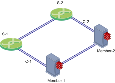
In this scenario:
If Member 1, its NIC, or S-1 fails, Member 2 becomes the only active member, connecting to switch S-2 over network C-2. If any component fails (Security Gateway, NIC, or switch), the result of the failover is that no further redundancy exists. A further failure of any active component completely stops network traffic.
Link Aggregation provides High Availability of NICs. If one fails, the other can function in its place. This functionality is in High Availability mode and in Load Sharing mode.
The Link Aggregation High Availability mode, when deployed with ClusterXL, enables a higher level of reliability by providing granular redundancy in the network. This granular redundancy is achieved by using a fully meshed topology, which provides for independent backups for both NICs and switches.
A fully meshed topology further enhances the redundancy in the system by providing a backup to both the interface and the switch, essentially backing up the cable. Each cluster member has two external interfaces, one connected to each switch.
In this scenario:
In Link Aggregation High Availability mode, when the Security Gateway is part of a cluster, bond internal failover can occur in one of these cases:
Either of these failures will induce a failover within the interface bond, or between cluster members, depending on the circumstances. The section below describes the two types of failover processes.
When a failure is detected, a log is recorded. You can see it in SmartView Tracker.
Do these procedures to create an interface bond: |
Before you define an interface bond, make sure the slave (physical) interfaces do not have IP addresses:
sysconfig
Network ConnectionsConfigure connection.Remove IP from interfaceDisconnected interfaces are cluster member interfaces that are not monitored by the ClusterXL mechanism. If a disconnected interface fails, failover does not occur.
If cluster members run on Gaia OS R77.20 and higher:
You do not need to manually configure the slave interfaces as disconnected (in the $FWDIR/conf/discntd.if
If cluster members run on SecurePlatform OS:
When the slave interfaces are without IP addresses, define the bond:
sysconfig
Network ConnectionsAdd new connectionBondnHigh AvailabilityA primary slave interface, after failing and coming back up, automatically returns to Active status, even if failover to the other interface occurred. If there is no primary interface, failover causes the other interface to become active and remain so until it fails.
After installation or failover, it is recommended to verify that the bond is up, by displaying bond information.
cphaprob -a if
Make sure that the bond status is reported as UP.
cphaconf show_bond <bond name>
Check that the bond is correctly configured.
In Link Aggregation High Availability mode, ClusterXL monitors VLAN IDs for connectivity failure or miscommunication, and initiate a failover when a failure is detected.
In a VLAN-enabled switched environment, ClusterXL monitors the VLAN with the lowest ID number. The monitoring is conducted by sending ClusterXL Control Protocol (CCP) packets on round-trip paths at a set interval. The lowest VLAN ID indicates the status of the physical connection. This VLAN ID is always monitored, and a connectivity failure causes ClusterXL to initiate a failover. ClusterXL will not detect a VLAN configuration problem on the switch.
You use bond interfaces for synchronization interface redundancy on Gaia and SecurePlatform platforms. The use of more than one physical synchronization interface (1st sync, 2nd sync, 3rd sync) is not supported.
Requirements and Limitations:
To configure bond interfaces for sync High Availability:
See the R77 Gaia Administration Guide for the procedures for defining bond interfaces on Gaia platforms.
Make sure that the slave interfaces do not have IP addresses assigned to them.
cphaprob -a if
In This Section |
In Link Aggregation Load Sharing mode:
Note - Link Aggregation Load Sharing mode requires SecureXL to be enabled on each cluster member.
Creating a Load Sharing bond is similar to creating a High Availability bond. The procedures for removing IP addresses from slaves, disconnecting slave interfaces, and verifying the bond are the same.
To create a Load Sharing bond:
To define the interface bond:
sysconfig
Network ConnectionsAdd new connectionBondnLoad Sharing.
|
Note - The Critical Required Interfaces feature is supported for ClusterXL only. |
A bond in Load Sharing mode is considered to be down when fewer than a critical minimum number of slave interfaces remain up. When not explicitly defined, the critical minimum number of interfaces in a bond of n interfaces is n-1. Failure of a second interface will cause the entire bond to be considered down, even if the bond contains more than two interfaces.
If a smaller number of interfaces will be able to handle the expected traffic, you can increase redundancy by explicitly defining the number of critical interfaces. Divide your maximal expected traffic speed by the speed of your interfaces and round up to a whole number to determine an appropriate number of critical interfaces.
To explicitly define the number of critical interfaces, create and edit the following file:
$FWDIR/conf/cpha_bond_ls_config.conf
Each line of the file should be of the following syntax:
<bondname> <critical#>
For example, if bond0bond1
bond0 5
bond1 3
In this case bond0bond1
These are sample configuration commands for Cisco switches.
Switch#conf t Switch(config)#port-channel load-balance src-dst-ip Switch(config)#interface FastEthernet <all the participating interfaces> Switch(config-if)#channel-group 1 mode active Switch(config-if)#channel-protocol lacp Switch(config-if)#exit Switch(config)#interface port-channel 1 Switch(config-if)#switchport access vlan <the wanted vlan number> Switch(config-if)#end Switch#write |
Switch#conf t Switch(config)#port-channel load-balance src-dst-ip Switch(config)#interface FastEthernet <all the participating interfaces> Switch(config-if)#channel-group 1 mode on Switch(config-if)#exit Switch (config)#interface port-channel 1 Switch(config-if)#switchport access vlan <the wanted vlan number> Switch(config-if)#end Switch#write |
VLANs can be defined on an interface bond in the same way as on a regular interface.
To define a VLAN on an interface bond:
sysconfig
Network ConnectionsAdd new connectionVLANTo get the best performance, use static affinity for Link Aggregation.
If you are running Performance Pack in a multi-core system, after you define bonds, set affinities manually. Use the -ssim affinity
|
Note - sim affinity commands take effect only if the Performance Pack is enabled and actually running. Performance Pack begins running when you install a Policy for the first time. |
For optimal performance, set affinities according to the following guidelines:
sim affinity s cat /proc/net/bonding/<bond name>.
For example, you might have four processing cores (0-3) and six interfaces (0-5), distributed among two bonds:
bond0 |
bond1 |
|---|---|
eth0 |
eth3 |
eth1 |
eth4 |
eth2 |
eth5 |
Two of the cores will need to handle two interfaces each. An optimal configuration can be:
bond0 |
|
bond1 |
|
|---|---|---|---|
eth0 |
core 0 |
eth3 |
core 0 |
eth1 |
core 1 |
eth4 |
core 1 |
eth2 |
core 2 |
|
|
|
|
eth5 |
core 3 |
cphaconf show_bond |
See status of one interface bond or summary of all bonds |
|||||||
|---|---|---|---|---|---|---|---|---|
Syntax |
|
|||||||
Options |
|
|
||||||
Example |
[Expert@GW-1]# cphaconf show_bond bond0 Bond name: bond0 Bond mode: Load Sharing Bond status: UP Balancing mode: 802.3ad Layer3+4 Load Balancing Configured slave interfaces: 4 In use slave interfaces: 4 Required slave interfaces: 2 Slave name | Status | Link ----------------+-----------------+------- eth2 | Active | Yes eth3 | Active | Yes eth4 | Active | Yes eth5 | Active | Yes |
|||||||
Comments |
The report results show:
|
cphaconf failover_bond |
Starts interface bond internal failover (High Availability only) |
|||||
|---|---|---|---|---|---|---|
Syntax |
|
|||||
Parameters |
|
|
chaprob -a if |
Displays status of all interface bonds and VLANs |
|---|---|
Syntax |
|
Example |
[Expert@GW-1]# cphaprob -a if Required interfaces: 5 Required secured interfaces: 1 bond0 UP non sync(non secured), broadcast, bond, can failover bond2 UP sync(secured), multicast, bond Load Sharing bond1 UP non sync(non secured), multicast, bond Load Sharing Virtual cluster interfaces: 4 bond0 192.168.34.60 bond1.60 10.34.60.1 bond1.61 10.34.61.1 bond1.62 10.34.62.1 |
Comments |
Use this command to see if a High Availability bond can failover. |
In This Section |
cphaconf show_bond <bond-name>
cphaprob state
If any of the cluster members have a firewall State other than active, cphaprob state troubleshooting.
When using certain switches, connectivity delays may occur during some internal bond failovers. With the various features that are now included on some switches, it can take close to a minute for a switch to begin servicing a newly connected interface. These are suggestions for reducing the startup time after link failure.
The PortFast feature should never be used on ports that connect to switches or hubs. It is important that the Spanning Tree complete the initialization procedure in these situations. Otherwise, these connections may cause physical loops where packets are continuously forwarded (or even multiply) in such a way that can cause the network to fail.
The following are the commands necessary to enable PortFast on a Gigabit Ethernet 1/0/15 interface of a Cisco 3750 switch running IOS.
cisco-3750A# conf t
cisco-3750A(config)# interface gigabitethernet1/0/15
cisco-3750A(config-if)# spanning-tree portfast
cisco-3750A(config-if)# end
cisco-3750A# write
A number of synchronization and ClusterXL capabilities are controlled by means of Security Gateway configuration parameters. Run these commands on the Security Gateway as follows:
|
Parameter is any of the parameters described in the following sections.
Changes to their default values must be implemented on all cluster members. Setting different values on cluster members can cause configuration problems and possibly connection failures.
All these configuration parameters can be configured to survive a boot. The way to do this varies with the operating system.
Security Gateway configuration parameters that are changed using the fw ctl set int command do not survive reboot. The way to do make them survive a reboot varies with the operating system. In the following instructions, Parameter is any of the parameters described in the following sections.
When you install IPSO or run Voyager for the first time on a new platform, the Firewall Kernel Tuning Configuration page does not appear. If a customer service representative instructs you to use this page, you must first display it by performing these steps:
# dbset advanced:loader tThe following Security Gateway configuration parameters are used to control the clustering and synchronization timers. Changing the default values is not recommended.
Clustering and Synchronization timers
Parameter |
Meaning |
Default Value |
|---|---|---|
|
The frequency of ClusterXL operations on the cluster.
Operations occur every: |
1 |
|
The frequency of sync flush operations on the cluster.
Operations occur every: |
1 |
|
Must be divisible by 10 with no remainders. |
10 |
The reason for blocking new connections is that new connections are the main source of new synchronization traffic, and synchronization may be put at risk if new traffic continues to be processed at this rate.
A related error message is: "FW-1: State synchronization is in risk. Please examine your synchronization network to avoid further problems!".
Reducing the amount of traffic passing through the Security Gateway protects the synchronization mechanism. See sk43896.
Note that blocking new connections when sync is busy is only recommended for Load Sharing ClusterXL deployments. While it is possible to block new connections in High Availability mode, doing so does not solve inconsistencies in sync, as High Availability mode precludes that from happening. This parameter can be set to survive boot using the mechanism described in How to Configure a Security Gateway to Survive a Boot.
|
|
|
2 (except for data connections) |
|
4 (except for data connections) |
|
8 (the control connection should be established or allowed) |
|
16 (the control connection should be established or allowed) |
The Active mode in SmartView Tracker shows open connections through Security Gateways that send logs to the active log file on the Security Management Server. The Active mode can slow down synchronization because the synchronization mechanism randomly drops Active connection updates. This issue generates SmartView Tracker error messages. For this reason, Check Point does not recommend using the Active mode view for a heavily loaded cluster.
The fwlddist_buf_size parameter controls the size of the synchronization buffer, as expressed in words (one word equals four Bytes). Words are used for synchronization and the SmartView Tracker Active mode. The default buffer size is 16k words. The maximum value is 64k words and the minimum value is 2k words.
You can change the fwlddist_buf_size parameter as necessary and the change is applied only after you restart the member. Make sure that that changed parameter is correct after you restart the member. See How to Configure Security Gateway Configuration Parameters for the procedures.
ClusterXL prevents out-of-state packets in non-sticky connections. It does this by holding packets until a Sync ACK is received from all other active cluster members. If for some reason a Sync ACK is not received, the Security Gateway on the cluster member will not release the packet, and the connection will not be established.
To find out if held packets are not being released, run the fw ctl pstat command. If the output of the command shows that the Number of Pending Packets is large under normal loads (more than 100 pending packets), and this value does not decrease over time, use the fwldbcast_pending_timeout parameter to reduce the number of pending packets.
Change the value of fwldbcast_pending_timeout from the default value of 50 to a value lower than 50.
The value is in ticks units, where each tick is equal to 0.1 sec, so that 50 ticks is 5 seconds.
The value represents the time after which packets are released even if Sync ACKs are not received.
When a cluster member comes up after being rebooted (or after cpstart), it has to perform Full Synchronization. As a first step in the Full Synchronization process, it performs a handshake with one of the other active cluster members. Only if this handshake succeeds does the cluster member continue with the Full Synchronization process.
The extended handshake that takes place (by default) exchanges information between cluster members. This information includes version information, information about the installed Check Point products, and can include information about which the VPN kernel tables are currently active. The extended handshake is unrelated to the exchange of kernel table information that happens later in the Full Synchronization.
All cluster members must have the same Check Point products and versions installed. The extended handshake identifies when different products are installed on the cluster members. When different products are installed, a console warning and a log message are issued.
In order to support backward compatibility, it is possible to change the behavior of the extended handshake by means of the following Gateway Configuration Parameters. How to edit these parameters is explained in Advanced Cluster Configuration:
Disconnected interfaces are cluster member interfaces that are not monitored by the ClusterXL mechanism.
You may wish to define an interface as disconnected if the interface is down for a long time, and you wish the cluster member to continue to be active.
The processes listed below are equivalent to defining a non-monitored interface from the Topology page, with the exception that the GUI method works only for interfaces that have a defined IP address.
Create a file under $FWDIR/conf/discntd.if

