Print Download PDF Send Feedback

Previous

Next

Configuring the Cluster Object and Members

Included Topics

Overview

Using the Wizards

Manual Configuration

Overview

You can use one of these procedures to define a cluster object and its members:

The Cluster Gateway Properties window lets you:

Using the Wizards

This version includes two wizards:

Small Appliance Wizard

The Small Appliance Wizard is recommended for these Check Point appliances:

To create a new cluster with the Small Appliance Wizard:

  1. In SmartDashboard, right-click Check Point in the Network Objects tree.
  2. Select Security Cluster > Small Office Appliance.
  3. In the Check Point Security Gateway Cluster Creation window, click Wizard Mode.
  4. In the Cluster General Properties window, enter a unique name for the cluster.
  5. In the Cluster Members window:
    1. Enter the member name and IPv4 addresses for each member.
    2. Enter the one-time password for SIC trust.
  6. In the Configure WAN Interface page, configure the cluster virtual interface IP address.
  7. Define the virtual IP addresses for the other cluster interfaces.
  8. Click Next, and then Finish to complete the wizard.

After you finish the wizard, we recommend that you open the cluster object and manually do these steps:

Check Point Appliance or Open Server Wizard

The Check Point Appliance or Open Server Wizard is recommended for enterprise grade appliances and open server platforms.

To create a new cluster with the Appliance or Open Server Wizard:

  1. In SmartDashboard, right-click Check Point in the Network Objects tree.
  2. Select Security Cluster > Check Point Appliance/Open Server.
  3. In the Check Point Security Gateway Cluster Creation window, click Wizard Mode.
  4. In the Cluster General Properties window, enter or select:
    • Cluster Name - Unique name for the cluster
    • Cluster IPv4 and IPv6 address - Virtual Management IP addresses for this cluster.

      Important: You must define a corresponding IPv4 address for every IPv6 address. This release does not support pure IPv6 addresses.

    • Choose the Cluster Solution - Select Check Point ClusterXL and then select High Availability or Load Sharing.
  5. In the Cluster Member Properties window, click Add > New Cluster Member to configure each member.
    1. Enter the physical IPv4 and IPv6 addresses.

      Note: Make sure that you do not define IPV6 address for sync interfaces. The wizard does not let you define an interface with an IPv6 address as a sync interface.

    2. Enter and confirm the SIC trust activation key.
  6. In the Cluster Topology window, define a network objective (Role) for each network interface and, if necessary, define the virtual cluster IP addresses.

    The wizard automatically calculates the subnet for each network and assigns it to the applicable interface on each member. The calculated subnet shows in the upper section of the window.

    The available network objectives are:

    • Cluster Interface - A cluster interface that connects to an internal or external network. Enter the cluster virtual IP addresses for each network (internal or external). These addresses must be located in the calculated subnet.
    • Cluster Sync Interface - A cluster synchronization interface. You must define one or more synchronization interfaces for redundancy. If you are using more than one synchronization interface, define which interface is the primary, secondary, or tertiary interface. Synchronization redundancy is not supported on Small Business appliances. On these appliances, you can only select 1st sync and only for the LAN2/SYNC interface. You cannot configure VLANs on the synchronization interface.
    • Monitored Private - An interface that is not part of the cluster, but ClusterXL monitors the member state and failover occurs if a fault is detected.
    • Non Monitored Private - ClusterXL does not monitor the member state and there is no failover.

      This option is recommended for the management interface.

  7. Click Next and then Finish to complete the wizard.

After you finish the wizard, we recommend that you open the cluster object and do these procedures:

Manual Configuration

The Cluster Gateway Properties window contains many different ClusterXL properties as well as other properties related to Security Gateway and Software Blade functionality. This section includes only the properties and procedures directly related to ClusterXL. See the applicable Administration Guides for these non-ClusterXL properties.

Configuration Steps

Configuring General Properties

Defining Cluster Members

Working with Cluster Topology

Changing the Synchronization Interface

Configuring General Properties

To configure the general properties of a cluster:

  1. Enter a unique name for this cluster object in the designated field.
  2. Enter the virtual cluster IPv4 and IPv6 addresses.
  3. Select the hardware platform, Check Point version and operating system.
  4. Select ClusterXL and other Network Security Software Blades as necessary.

Defining Cluster Members

To configure a cluster member:

  1. Go to the Cluster Members page.
  2. Click Add > New Cluster Member.
  3. In the Cluster Members Properties window General tab, enter a cluster member Name and its physical IP addresses (IPv4 and IPv6). The Security Management Server must be able to connect to the cluster members at these IP addresses. These IP addresses can be an internal, external. You can use a dedicated management interface on each cluster member.

    Important - You must define a corresponding IPv4 address for every IPv6 address. This release does not support the configuration of only IPv6 addresses.

  4. Click Communication, and initialize Secure Internal Communication (SIC) trust.
  5. Configure NAT and VPN settings on the appropriate tabs as required.

Working with Cluster Topology

IPv6 Considerations

To activate IPv6 functionality for an interface, define an IPv6 address for the applicable interface on the cluster and on each member. All interfaces configured with an IPv6 address must also have a corresponding IPv4 address. If an interface does not require IPv6, only the IPv4 definition address is necessary.

Note - You must configure synchronization interfaces with an IPv4 address only. This is because the synchronization mechanism works using IPv4 only. All IPv6 information and states are synchronized using this interface.

To open the In the Topology page, click Edit Topology. The Edit Topology window opens.

pg36_EditTopology_IPv6

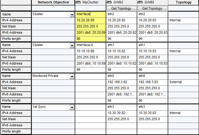
This window is a table that shows topology information for all detected interfaces in the cluster object and its related members. The rows show the interfaces. The columns contain these information categories for each interface:

If you used the Cluster Properties window to manually create a cluster, an empty table shows. You manually add and configure the interfaces in the table.

If you created the cluster using one of the wizards, the topology is calculated automatically and shows in the Edit Topology window. You can change the IP addresses and other properties directly in this window.

To configure cluster virtual interface Properties:

  1. Right-click an interface in the Cluster column and select Edit Interface.
  2. In the Interface Properties window General tab, configure the name and IP addresses.

    Note: Make sure that you do not define IPV6 address for sync interfaces. The wizard does not let you define an interface with an IPv6 address as a sync interface.

    Important: You must define a corresponding IPv4 address for every IPv6 address. This release does not support pure IPv6 addresses.

  3. In the Topology tab:
    1. Select External or Internal.
    2. For internal interfaces configure the IP address located behind this interface and elect Interface leads to DMZ if necessary.
  4. In the Member Network tab, enter a member interface IP address in the same subnet as the cluster virtual IP address.

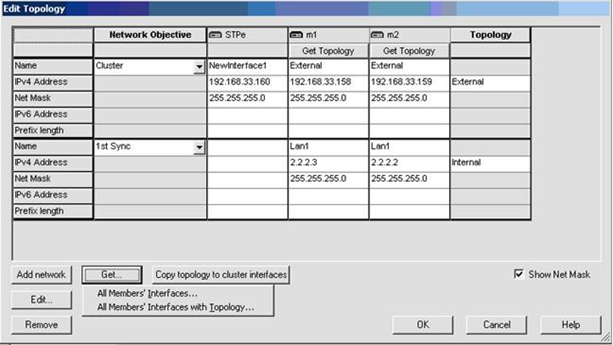
    Cluster members can be located on a different subnet than the cluster virtual IP address. When this occurs, use this tab to map the member IP address to the cluster virtual IP address. This advanced option is explained in Configuring Cluster Addresses on Different Subnets.

  5. In the Network Objective column, select an objective for each network from the list. The options are explained in the online help.

    To define a new network, click Add Network.

    The available network objectives are:

    • Cluster - An interface that connects to an internal or external network.

      Enter the cluster virtual IPv4 and IPv6 addresses for each network (internal or external). These addresses must be located in the calculated subnet.

    • Cluster + Sync Address - A cluster interface that also works as a Synchronization Interface. These interfaces must be located in the calculated subnet.
    • Sync Address - An interface used exclusively for member synchronization.
    • Monitored Private - An interface that is not part of the cluster, but ClusterXL monitors the member state and failover occurs if a fault is detected.
    • Non-Monitored Private - An interface that is not part of the cluster. ClusterXL does not monitor the member state and there is no failover.

      This option is recommended for the management interface.

Changing the Synchronization Interface

To change the synchronization interface on your cluster members:

  1. In the operating system WebUI or command line, add a new interface on each member.
  2. In SmartDashboard, open the cluster object.
  3. In the Gateway Cluster Properties window, go to the Topology page and click Edit.
  4. Click Get > All Member's Interfaces with Topology.
  5. Select the old interfaces and click Remove.
  6. Configure the new interfaces as Synchronization interfaces.
  7. Install policy.
  8. In the operating system WebUI or command line, delete the old interface on each member.

Configuring Gateway Cluster in Bridge Mode

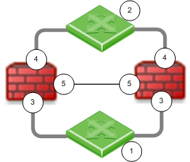
You can configure cluster gateways for bridge mode in different deployments Active/Standby mode or Active/Active mode.

bridge cluster

Item

Description

1 and 2

Switches

IUG_FW Icon

Security Gateway Firewall bridging Layer-2 traffic

3

eth1

4

eth2

5

eth3 - the ClusterXL Sync interface

Configuring Active/Standby Mode

This is the preferred mode in topologies that support it.

In Active-Standby mode, ClusterXL decides the cluster state. The standby member drops all packets. It does not pass any traffic, including STP/RSTP/MSTP. If there is a failover, the switches are updated by the Security Gateway to forward traffic to the new active member.

If you use this mode, it is best to disable STP/RSTP/MSTP on the adjacent switches.

To configure Active/Standby mode:

  1. Configure the cluster.
  2. Run: cpconfig
  3. Enter 8, to select Enable Check Point ClusterXL for Bridge Active/Standby.
  4. Confirm: y
  5. Reboot the cluster member.
  6. Install Policy.
  7. Test the cluster state: cphaprob state

    The output should be similar to:

Cluster Mode: High Availability (Active Up, Bridge Mode) with IGMP Membership
Number     Unique Address     Firewall State (*)
1 (local>  2.2.2.3            Active
2          2.2.2.2            Standby

Configuring Active/Active Mode

When you define a bridge interface on a Security Gateway cluster, Active/Active mode is activated by default.

Before you begin, install ClusterXL High Availability on a Gaia appliance or open server.

To configure Active/Active mode, do these steps on each member of the cluster:

  1. Configure dedicated management and Sync interfaces.
  2. Add a bridge interface, as in a single gateway deployment.

    Do not configure an IP address on the newly created bridge interface.

  3. In SmartDashboard, add the cluster object:
    1. Open Topology of the cluster object.
    2. Get the cluster topology.
    3. Make sure the dedicated management and Sync interfaces are configured.
    4. Make sure the bridge interface and bridge ports are not in the topology.

    Bridge port topology cannot be defined. It is external by default.

    cluster topology

  4. Install Policy.
  5. Test the cluster state: cphaprob stat

    The output should be similar to:

    Cluster Mode: High Availability (Active Up, Bridge Mode) with IGMP Membership
    Number Unique Address Firewall State (*)
    1 (local> 2.2.2.3 Active
    2 2.2.2.2 Active

  6. Make sure that cluster is configured as High Availability in SmartDashboard.

Confirming the High Availability Configuration

After you configure Active/Active mode, the output for chpaprob state shows that the Firewall State is Active/Active. Make sure that the cluster is configured for High Availability.

To confirm the High Availability configuration:

  1. Open the cluster object.
  2. In the cluster Properties window, click ClusterXL.
  3. In the Cluster Mode section, make sure that High Availability is selected.
  4. Click OK.

Cluster Between Four Switches

You can configure a bridged cluster between four switches, in Active/Active mode.

Active/Standby mode is not supported.
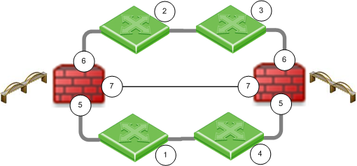
bridge in cluster with 4 switches

Item

Description

1, 2, 3, 4

Switches

IUG_FW Icon

Security Gateway Firewall bridging Layer-2 traffic

5

eth1

6

eth2

7

eth3 - the ClusterXL Sync interface

See also: Link Aggregation with ClusterXL in Layer-2

Configuring Link State Propagation

You can bind two ports together, so that when the link state for one port goes down, the other port also goes down. This lets a switch detect and react to a link failure on the other side of a bridge or another part of the network.

This feature is available in one of these modes:

Link state propagation is supported on these Check Point appliance line cards:

For example:
fw_lsp_pair1=”eth1,eth2"

Note - You can add up to four lines to this file, one for each pair.

Note: The below procedures are applicable to R77.20 and higher.

To configure Link State Propagation for automatic port detection:

  1. Open FWDIR/modules/fwkern.conf in a text editor.

    If there is no fwkern.conf file, create a new one.

  2. Add this line:

    fw_link_state_propagation_enabled=1

  3. Reboot the computer.

To create port pairs automatically:

  1. Open FWDIR/modules/fwkern.conf in a text editor.

    If there is no fwkern.conf file, create a new one.

  2. Add these lines:

    fw_link_state_propagation_enabled=1

    fw_manual_link_state_propagation_enabled=1

    fw_lsp_pair<1-4>=”<interface_name1,interface_name2>”

  3. Reboot the computer.

    Note - Link State Propagation is a Firewall Software Blade feature. It is supported for Security Gateways and clusters. You must configure Link State Propagation for each cluster member.