QoS Tutorial
Introduction
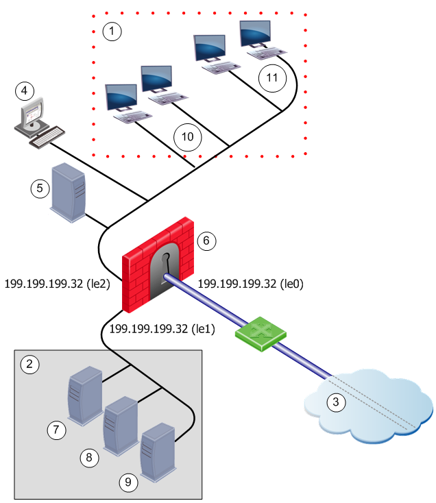
This chapter presents a step by step guide to building and installing a QoS Policy in QoS. This tutorial is based on an example network configuration.
Number
|
Description
|
Number
|
Description
|
1
|
Private Localnet
|
7
|
HTTP Server
|
2
|
DMZ
|
8
|
HTTP Server
|
3
|
Internet
|
9
|
FTP server
|
4
|
Cambridge SmartConsole
|
10
|
Marketing
|
5
|
Oxford Security Management Server
|
11
|
Engineering
|
6
|
London QoS gateway
|
|
|
This example shows a typical network configuration for an organization with offices located in London, Oxford and Cambridge. The QoS gateway is located in London where the gateway to the Internet will comprise three interfaces. The Security Management Server is located at Oxford while the SmartConsole is installed at Cambridge. Within the private local network there are the Marketing and Engineering departments. In this tutorial you are shown how a QoS policy is implemented to regulate and optimize the flow in Internet traffic to these departments.
Building and Installing a QoS Policy
Complete these steps to create and install a QoS Policy on the example network.
- Install these gateways as needed.
Computer
|
Function
|
Required Gateway
|
London
|
QoS Gateway
gateway to the Internet
|
QoS Gateway
Security Gateway (required)
|
Oxford
|
Security Management Server
|
Security Management Server QoS Add-on
|
Cambridge
|
SmartConsole
|
Security Gateway
|
- Open tab.
- Decide on the type of QoS Policy to implement:
- Define the network objects to be used in the Rule Base.
Define only those objects that are explicitly used in the Rule Base. You do not have to define all of the network.
- Define proprietary services used on the network.
You do not have to define the commonly used services. These are already defined for you in QoS. In most cases you need only specify a name for network objects and services. QoS obtains the object's properties from the applicable databases (DNS, YP hosts file).
- Create the QoS Rule Base that make up the Policy.
- Install the Policy on the QoS Security Gateway.
These steps are described in the sections that follow.
Installing Check Point Gateways
Detailed installation instructions are available in the R77 Installation and Upgrade Guide.
Install QoS in this sequence:
- Install QoS and Firewall on London.
- Install SmartConsole on Cambridge.
- Install Security Management Server on Oxford.
- On Oxford, define Cambridge as a SmartConsole.
- On Oxford, define the administrators who will be allowed to manage the QoS Policy.
- Enable SIC between the Security Management Server in Oxford and the QoS gateway in London.
Starting SmartDashboard
This section describes how to start SmartDashboard and access the QoS tab.
To Start SmartDashboard
- From the Start menu, select Programs > Check Point SmartConsole R77.10 > SmartDashboard. The Welcome to Check Point SmartDashboard window shows.
- Log in using one of these authentication methods:
- User Name and Password
- Certificate
- Enter the name of the Security Management Server as:
- A DNS resolvable name
- An IP address
Select Read Only if you do not wish to change the policy.
- Optionally add a session description explaining why you are changing the security policy. This text shows as a log entry in SmartView Tracker (Audit mode) in the Session Description column.
Note: If the Session Description column does not show in SmartView Tracker, use the Query Properties pane to display it. For more on SmartView Tracker, see the R77 SmartView Tracker Administration Guide.
- Click Login.
SmartDashboard opens.
- Click the QoS tab to show the QoS Rule Base.
Determining QoS Policy
To implement a good QoS Policy, find out how the network is used. Identify and prioritize the types of traffic. Identify users and their needs. For example:
- HTTP traffic must be allocated more bandwidth than RealAudio.
- Marketing must be allocated more bandwidth than Engineering.
You will create the rules to implement this policy in Creating a Rule Base.
Defining the Network Objects
Define these Network Objects:
- London, the gateway on which the QoS gateway is running
- Sub-networks for the Marketing and Engineering departments
As an example, this step shows how to define the London gateway.
From the...
|
Do this...
|
Manage menu
|
- From the Manage menu, choose Network Objects.
The Network Objects window opens.
- Click New and choose Check Point > Gateway from the menu.
The Check Point Gateway - General Properties window opens.
|
Objects toolbar
|
- If the Objects toolbar is not visible, then, from the View menu choose Toolbars > Objects to display it.
- Select from the toolbar.
The Network Objects window opens.
- Click New and choose Check Point > Gateway from the menu. The Check Point Gateway -
General Properties window opens.
|
Network Objects tree
|
- Right click Network Objects in the Network Objects tree and choose New > Check Point > Gateway from the menu.
The Check Point Gateway - General Properties window opens.
- In the Check Point Gateway - General Properties window enter the information shown in the next table below to define London's gateway.
|
London's Check Point Gateway - General Properties Window
Field
|
Value
|
Explanation
|
Name
|
London
|
This is the name by which the object is known on the network; the response to the hostname command.
|
IP Address
|
192.32.32.32
|
This is the interface associated with the host name in the DNS — get this by clicking Get Address.
For gateways, this should always be the IP address of the external interface.
|
Comment
|
QoS gateway
|
This is the text that is displayed at the bottom of the Network Objects window when this object is selected
|
Check Point Products
|
Select the Version from the drop‑down list.
|
These settings specify the Check Point products installed on London, and their version number.
Note that if multiple Check Point products are installed on a machine, they must all be the same version number.
|
SIC
|
|
Establishes a secure communication channel between Check Point gateways.
|
Defining Interfaces on the Gateway
- Click Topology in the tree on the left side of the Check Point Gateway -London window.
The Topology page Check Point Gateway - London window opens.
- Configure the interfaces according to the data in these tables:
Field Values — Interface Properties Window
|
|
|
Field
|
Value
|
Explanation
|
General tab
|
Name
|
le0
|
|
Net Address
|
192.32.32.32
|
|
Net Mask
|
255.255.255.0
|
|
Topology tab
|
Topology
|
Check External (leads out to the Internet).
|
Specifies to which network this interface leads.
|
Anti-Spoofing
|
Check Perform Anti-Spoofing based on network topology.
|
Specifies that each incoming packet will be examined to ensure that its source IP address is consistent with the interface through which it entered the machine.
|
Spoof Tracking
|
Check Log.
|
Specifies that when spoofing is detected, the event will be logged.
|
Field Values — Interface Properties Window — le1
|
|
|
Field
|
Value
|
Explanation
|
General tab
|
Name
|
le1
|
|
Net Address
|
192.32.42.32
|
|
Net Mask
|
255.255.255.0
|
|
Topology tab
|
Topology
|
Check External (leads out to the Internet).
|
Specifies to which network this interface leads.
|
IP addresses behind this interface
|
Check Network defined by the interface IP and Net Mask.
|
Specifies that each incoming packet will be examined to ensure that its source IP address is consistent with the interface through which it entered the machine.
|
Anti-Spoofing
|
Check Perform Anti-Spoofing based on network topology.
|
Specifies that each incoming packet will be examined to ensure that its source IP address is consistent with the interface through which it entered the machine.
|
Spoof Tracking
|
Check Log.
|
Specifies that when spoofing is detected, the event will be logged.
|
Field Values — Interface Properties Window — le2
|
|
|
Field
|
Value
|
Explanation
|
General tab
|
Name
|
le2
|
|
Net Address
|
199.199.199.32
|
|
Net Mask
|
255.255.255.0
|
|
Topology tab
|
Topology
|
Check External (leads out to the Internet).
|
Specifies to which network this interface leads.
|
IP addresses behind this interface
|
Check Network defined by the interface IP and Net Mask.
|
Specifies that each incoming packet will be examined to ensure that its source IP address is consistent with the interface through which it entered the machine.
|
Anti-Spoofing
|
Check Perform Anti-Spoofing based on network topology.
|
Specifies that each incoming packet will be examined to ensure that its source IP address is consistent with the interface through which it entered the machine.
|
Spoof Tracking
|
Check Log.
|
Specifies that when spoofing is detected, the event will be logged.
|
After the three interfaces have been defined, they are listed in the Check Point Gateway - London - Topology window.
- Click OK.
Define the QoS Properties for the Interfaces
- In the Check Point Gateway - London - Topology window, double‑click London's external interface (le0), or select it and click Edit.
The Interface Properties window opens.
- Click the QoS tab.
The Interface Properties - QoS tab opens.
- Select Inbound Active and Outbound Active.
- From the Rate list set both rates to 192000 - T1 (1.5 Mbps).
- Click OK.
To exit the Interface Properties window.
- Click OK.
To exit the Check Point Gateway - London - Topology window.
Defining the Services
The QoS Policy required for this tutorial does not require the definition of new proprietary services. The commonly used services HTTP and RealAudio are already defined in QoS.
Creating a Rule Base
After defining your network objects and services, create the Rule Base that makes up the QoS policy. When you start SmartDashboard, the last Policy Package is shown. The Policy Package represents the Rule Bases of all the tabs that are shown in SmartDashboard.
This tutorial is concerned with the QoS Rule Base which is opened when you select the QoS tab. In this step, you create a new QoS Policy Package. After you have created the Policy Package, you must add the rules that will enforce the QoS Policy decided in Determining QoS Policy.
The new QoS Rule Base is created with a Default Rule (see Default Rule).
To Create a New Policy Package
- In SmartDashboard select New from the File menu.
The New Policy Package window opens.
- Enter the name in the New policy Package Name field.
- Select QoS.
- Select QoS policy (recommended).
- Click OK.
The new Policy Package is created together with a Default Rule and is displayed in the QoS tab.
To Create New Rules
This procedure describes how to create the two new rules required to enforce the Rule Base. Create two rules: Web Rule and RealAudio Rule.
- Click the QoS tab to access the QoS Rule Base.
- Right-click in the Name field of the QoS tab and select Add Rule above from the menu that is displayed. The Rule Name window is displayed.
- Enter Web Rule as the Rule Name.
- Click OK.
The rule is added to the Rule Base.
- Create a new rule with the name of RealAudio Rule.
The QoS tab in SmartDashboard lists all the rules in the Rule Base.
Rule Properties
A new rule has the default values assigned by the administrator. The next procedure describes how to change these rules to the values shown in the table below.
Changing Rules Default Values
Rule Name
|
Source
|
Destination
|
Service
|
Action
|
Web Rule
|
Any
|
Any
|
HTTP
|
Weight 35
|
RealAudio Rule
|
Any
|
Any
|
RealAudio
|
Weight 5
|
Default
|
Any
|
Any
|
Any
|
Weight 10
|
To Modify New Rules
- In the QoS tab, right-click in the Service field of the Web Rule.
- Select Add Objects from the menu.
The Add Object window opens.
- Select HTTP from the list.
- Click OK.
- Right-click in the Action field of the Web Rule.
- Select Edit Properties from the menu.
The QoS Action Properties window opens.
- Change the Rule Weight to 35.
- Click OK.
Classifying Traffic by Service
Usually, a full Rule Base will not explicitly define rules for all the "background" services (such as DNS and ARP). Background services are handled by the Default rule.
The structure of the Rule Base is shown at the left of the window as a tree, with the Default Rule at the bottom. (For a description of the Rule Base window, see Basic Policy Management).
Connections receive bandwidth according to the weights (priority) assigned to the rules that apply to them. The table below describes what occurs when there are four active connections. Note that bandwidth allocation is constantly changing.
Service Rules - Four Active Connections
Connections
|
Relevant rule
|
Bandwidth
|
Comments
|
HTTP
|
Web Rule
|
70%
|
35 / 50 (the total weights)
|
RealAudio
|
RealAudio Rule
|
10%
|
5 / 50
|
FTP
|
Default
|
sharing 20%
|
10 /50; a rule applies to all the connections together
|
TELNET
|
Default
|
sharing 20%
|
10 /50; a rule applies to all the connections together
|
Bandwidth is allocated between connections according to relative weight. As connections are opened and closed, QoS changes the bandwidth allocation according to the QoS Policy.
For example:
- If the HTTP, FTP and TELNET connections are all closed. The only remaining connection is the RealAudio connection. RealAudio receives 100% of the bandwidth.
- If the TELNET and FTP connections are closed, both HTTP and RealAudio benefit from the released bandwidth.
Service Rules - Two Active Connections
Connections
|
Relevant rule
|
Bandwidth
|
Comments
|
HTTP
|
Web Rule
|
87/5%
|
35 / 40 (the total weights)
|
RealAudio
|
RealAudio Rule
|
12.5%
|
5 / 40
|
Although RealAudio is assigned a very small weight compared to HTTP, it will not be starved of bandwidth no matter how heavy the HTTP traffic.
In practice, you will probably want to give a high relative weight to interactive services such as TELNET, which transfers small amounts of data but involves users issuing commands.
Classifying Traffic by Source
The second part of the QoS Policy (Marketing must be allocated more bandwidth than Engineering) is implemented by these rules:
Marketing is Allocated More Bandwidth Than Engineering
Rule Name
|
Source
|
Destination
|
Service
|
Action
|
Marketing Rule
|
Marketing
|
Any
|
Any
|
Weight 30
|
Engineering Rule
|
Engineering
|
Any
|
Any
|
Weight 20
|
Default
|
Any
|
Any
|
Any
|
Weight 10
|
Using the same principles described in To Create a New Rules and To Modify New Rules, create new rules in SmartDashboard and change them to match the values shown in the table above. The effect of these rules is equivalent to the rules shown here:
Connections
|
Relevant rule
|
Bandwidth
|
Comments
|
HTTP
|
Web Rule
|
70%
|
35 / 50 (the total weights)
|
RealAudio
|
RealAudio Rule
|
10%
|
5 / 50
|
FTP
|
Default
|
sharing 20%
|
10 /50
A rule applies to all the connections together
|
TELNET
|
Default
|
sharing 20%
|
10 /50
A rule applies to all the connections together
|
Except for:
- the different weights
- the fact that allocation is based on source rather than on services
Classifying Traffic by Service and Source
The table below shows all the rules in one Rule Base.
All the Rules Together
Rule Name
|
Source
|
Destination
|
Service
|
Action
|
Web Rule
|
Any
|
Any
|
HTTP
|
Weight 35
|
RealAudio Rule
|
Any
|
Any
|
RealAudio
|
Weight 5
|
Marketing Rule
|
Marketing
|
Any
|
Any
|
Weight 30
|
Engineering Rule
|
Engineering
|
Any
|
Any
|
Weight 20
|
Default
|
Any
|
Any
|
Any
|
Weight 10
|
In this Rule Base, bandwidth allocation is based both on sub-networks and on services.
First Rule Match Principle
In the Rule Base shown below:
Rule Name
|
Source
|
Destination
|
Service
|
Action
|
Web Rule
|
Any
|
Any
|
HTTP
|
Weight 35
|
RealAudio Rule
|
Any
|
Any
|
RealAudio
|
Weight 5
|
Marketing Rule
|
Marketing
|
Any
|
Any
|
Weight 30
|
Engineering Rule
|
Engineering
|
Any
|
Any
|
Weight 20
|
Default
|
Any
|
Any
|
Any
|
Weight 10
|
In a production environment, a connection can match more than one rule. QoS works according to a first rule match principle. Each connection is examined against the QoS Policy and receives bandwidth according to the Action defined in the first rule that is matched.
If a user in Marketing initiates an HTTP connection, the connection matches the Web Rule and the Marketing Rule. The Web Rule comes before the Marketing Rule in the Rule Base, so the connection is matched to the Web Rule and given a weight of 35.
To differentiate HTTP traffic by source, create sub-rules for the Web Rule. See Sub-Rules.
Guarantees and Limits
Bandwidth allocation can also be defined using guarantees and limits. You can define guarantees and limits for rules or for individual connections in a rule.
Rule Name
|
Source
|
Destination
|
Service
|
Action
|
Web Rule
|
Any
|
Any
|
HTTP
|
Weight 35
|
RealAudio Rule
|
Any
|
Any
|
RealAudio
|
Weight 5
|
Marketing Rule
|
Marketing
|
Any
|
Any
|
Weight 30
|
Engineering Rule
|
Engineering
|
Any
|
Any
|
Weight 20
|
Default
|
Any
|
Any
|
Any
|
Weight 10
|
The Web Rule shown in the Rule Base allocates 35% of available bandwidth to all the HTTP connections combined. The actual bandwidth allocated to connections that match this rule depends on:
- Total available bandwidth
- Open connections that match other rules
Note: 35% of available bandwidth (specified in the example above) is assured to Web Rule. Web Rule will get more bandwidth if there are fewer connections matched to other rules, but never less than 35%.
As an alternative to relative weights, a guarantee can be used to specify bandwidth as an absolute value (in Bytes per second). In this table, Web Rule is guaranteed 20 KBps:
Guarantee Example
Rule Name
|
Source
|
Destination
|
Service
|
Action
|
Web Rule
|
Any
|
Any
|
HTTP
|
Guarantee 20 KBps
Weight 35
|
RealAudio Rule
|
Any
|
Any
|
RealAudio
|
Weight 5
|
Marketing Rule
|
Marketing
|
Any
|
Any
|
Weight 30
|
Engineering Rule
|
Engineering
|
Any
|
Any
|
Weight 20
|
Default
|
Any
|
Any
|
Any
|
Weight 10
|
Connections matched to Web Rule will receive a total bandwidth of 20 KBps. Remaining bandwidth will be allocated to all the rules, Web Rule included, according to their weights.
For more on guarantees and limits, see Examples: Guarantees and Limits and Bandwidth Allocation and Rules.
Sub-Rules
Sub-rules are rules nested in a rule. For example, you can create a sub-rule that allocates more bandwidth to HTTP connections that originate in Marketing. Connections whose Source is marketing receive more bandwidth than other HTTP traffic. In this example, the marketing sub-rule and default sub-rule is below the Web Rule:
Defining Sub-Rules
|
|
|
|
|
Rule Name
|
Source
|
Destination
|
Service
|
Action
|
Web Rule
|
Any
|
Any
|
|
Weight 20
|
Start of Sub-Rule
|
Marketing HTTP
|
Marketing
|
Any
|
Any
|
Weight 10
|
Default
|
Any
|
Any
|
Any
|
Weight 1
|
End of Sub-Rule
|
Bandwidth is allocated to Web Rule according to its weight (20). This weight is divided between its sub-rules in a 10:1 ratio. Connections below Web Rule are allocated bandwidth according to the weights specified:
- 10 for HTTP traffic from the Marketing department
- 1 for everything else.
Note:
- There are two Default rules: one for the Rule Base and one for the Web Rule sub-rule.
- The Source, Destination and Service fields of the sub-rule must always be a "sub-set" of the parent rule.
To create a sub-rule:
- Right-click in the Name field of the rule in which you want to create the sub-rule.
- Select Add Sub-Rule.
Installing a QoS Policy
After you have defined the Rule Base, you can install the QoS Policy on the QoS gateways by selecting Install from the Policy menu.
The Install Policy window is displayed, showing a list of gateways defined as QoS gateways (see Defining the Network Objects).
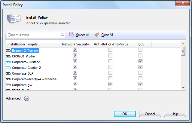
Select the QoS gateways on which to install the QoS Policy. QoS will enforce the QoS Policy on the directions specified in the interface properties of each selected gateway.
For more, see Implementing the Rule Base.
|

