


|
|
|
In This Section: |
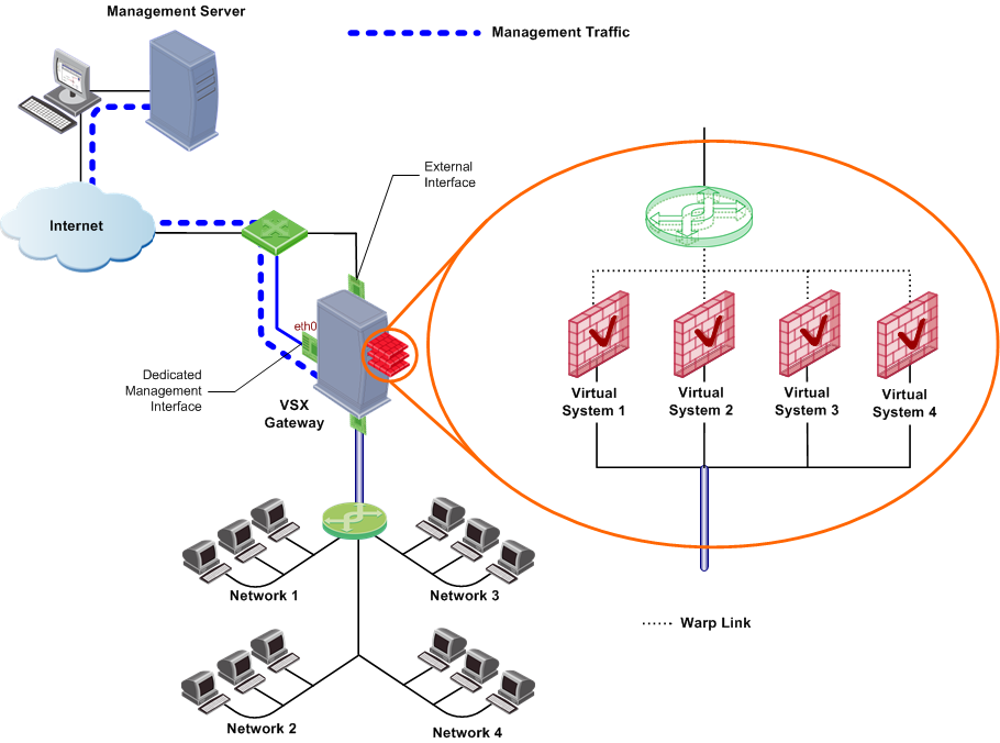
A VSX Gateway is a physical machine that hosts virtual "networks", consisting of virtual devices that provide the functionality of their physical network counterparts such as: Security Gateways, routers and switches.
A VSX Gateway performs the following tasks:
A VSX Gateway is a physical machine that hosts virtual "networks", consisting of virtual devices that provide the functionality of their physical network counterparts such as: Security Gateways, routers and switches.
A VSX Gateway performs the following tasks:
A management server (Security Management Server or Multi-Domain Server) connects to the VSX Gateway and provides provisioning and configuration services for virtual devices located on the VSX Gateway. You can connect the management server to the VSX Gateway using one of the following scenarios.
When using a local management server (Security Management Server or Multi-Domain Security Management), all management traffic is handled by a dedicated management interface (DMI) that connects the management server with the VSX Gateway. The dedicated management interface IP address can be either private or public.
When using a remote management server (Security Management Server or Multi-Domain Security Management), management traffic travels via an internal or external network to a VSX Gateway to the management interface. This architecture segregates management traffic from all other traffic passing through the VSX Gateway.
Check Point recommends that remote management connections use a dedicated management interface (DMI) that connects directly to a router or switch that leads to the external network or the Internet.
You can choose to use a non-dedicated management interface by connecting a Virtual Router or Virtual Switch to the management interface.
When management traffic passes through a Virtual Router or Virtual Switch, you must ensure that the associated Warp Link IP address originates from the remote network. Furthermore, if the remote management connection arrives via the Internet, you must assign a routable, public IP address.
A VSX deployment can be managed using one of the following interface schemes:
Check Point recommends that you use a DMI for management to segregate management traffic from routine "production" traffic enhanced performance, especially for end users.
When configuring a non-DMI deployment, you can define remote management connections only via a Virtual Switch or Virtual Router. Remote management connects via a Virtual System are not supported.
When using non-DMI for the following reasons:
This section describes virtual network components and their characteristics.
A Virtual System is a virtual security and routing domain that provides the functionality of a Security Gateway with full Firewall and VPN facilities. Multiple Virtual Systems can run concurrently on a single VSX Gateway.
Each Virtual System functions as an independent entity, much in the same way as each Security Gateway is independent from other Gateways. Each Virtual System maintains its own Software Blades, interfaces, IP addresses, routing table, ARP table and dynamic routing configuration. In addition, each Virtual System maintains its own:
A Virtual System in bridge mode implements native layer-2 bridging instead of IP routing. This lets you easily and transparently deploy a Virtual System in an existing network topology without reconfiguring the existing IP routing scheme.
A typical bridge mode scenario incorporates an 802.1q compatible VLAN switch on either side of the VSX Gateway. The Virtual System interfaces do not require IP addresses and it remains transparent to the existing IP network.
A Virtual System in the bridge mode:
A Virtual Router is an independent routing domain within a VSX Gateway that performs the functionality of physical routers. Virtual Routers are useful for connecting multiple Virtual Systems to a shared interface, such as the interface leading to the Internet, and for routing traffic from one Virtual System to another. Virtual Routers support dynamic routing.
Virtual Routers perform the following routing functions:
As with physical routers, each Virtual Router maintains a routing table with a list of route entries describing known networks and directions on how to reach them. Depending on the deployment requirements, multiple Virtual Routers can be configured.
To protect themselves, Virtual Routers inspect all traffic destined to, or emanating from themselves (for example, an ICMP ping to the Virtual Router IP address) based on the security policy. Traffic that is not sent to, or coming from the Virtual Router is not inspected by the Virtual Router policy and is sent to its destination.
By providing layer-2 connectivity, a Virtual Switch connects Virtual Systems and facilitates sharing a common physical interface without segmenting the existing IP network. As with a physical switch, each Virtual Switch maintains a forwarding table with a list of MAC addresses and their associated ports.
In contrast to a Virtual Router, when sharing a physical interface via a Virtual Switch there is no need:
You can create multiple Virtual Switches in a virtual network topology.
|
Note - When sharing a physical interface via a Virtual Switch, the IP addresses for Virtual Systems connected to a Virtual Switch should be allocated from the same subnet as the shared interface. |
This section describes the various types of interfaces and how they are used in a VSX configuration. The principal interface types are:
The following figure presents a simple example that illustrates how the various interface types are used in a VSX environment.
Notes:
Physical interfaces connect a VSX Gateway to internal and external networks, as well as to the management server. There are different types of physical interfaces (four types for a VSX Cluster) used in a VSX Gateway:
Additional physical interfaces can be installed and attached to any virtual device as required. A VSX Gateway can theoretically contain as many physical interfaces as permitted by gateway hardware and memory constraints.
Virtual Systems typically connect to protected VLAN networks using IEEE 802.1q compliant VLAN Interfaces. The networks are connected to ports on an 802.1q-compliant switch that trunks all traffic via a single physical interface to the VSX Gateway.
VSX uses VLAN tags to direct the Ethernet frames to the specific Virtual System handling each network. VSX assigns a virtual VLAN interface to each VLAN tag on a specific physical interface. For Example: VLAN tag 100 on eth3 will be assigned a virtual interface named eth3.100.
A Warp Link is a virtual point-to-point connection between a Virtual System and a Virtual Router or Virtual Switch. Each side of a Warp Link represents is a virtual interface with the appropriate virtual device.
R76 VSX automatically assigns a name to each virtual interface when administrators create the link. Warp Interfaces on the Virtual System side are assigned the prefix wrp and those on the Virtual Router / Virtual Switch side are assigned the prefix wrpj. In both cases, VSX appends a unique number to the prefix to form the interface name.
When connected to a Virtual Switch, VSX also assigns a unique MAC address to each Warp Link.
VSX lets you reduce the number of IP addresses required for a VSX network deployment when using one or more Virtual Routers. A Warp Link connected to a Virtual Router can "borrow" an existing IP address from another interface, instead of assigning a dedicated address to the interface leading to a Virtual Router. This capability is known as an Unnumbered Interface.
The previous figure illustrates a topology using unnumbered interfaces. In this example, the external interfaces for each Virtual System are unnumbered and borrow the IP address of the internal interfaces. Unnumbered interfaces act as the next hop from the Virtual Router.
The following limitations apply to Unnumbered Interfaces:
VSX supports two Check Point management models: Security Management Server and Multi-Domain Security Management. Both models provide central configuration, management and monitoring for multiple VSX Gateways and Virtual Systems. The choice of management model depends on several factors, including:
You can use either management model to manage a "physical" Security Gateway together with a VSX Gateway and Virtual Systems. You can also manage VPN communities and remote connections with either model.
|
Note - According to the Check Point EULA (End User License Agreement), a Security Gateway can only manage security policies for Virtual Systems belonging to a single legal entity. In order to manage Virtual Systems belonging to multiple legal entities, you need to deploy a Multi-Domain Security Management solution with a separate Domain Management Server for each legal entity. For more information regarding Licensing, refer to your Check Point Reseller. |
The Security Management Server model is appropriate for enterprise deployments containing many Virtual Systems. In this model, SmartDashboard connects to the VSX Gateway, which contains the Virtual Systems, and directly manages each Virtual System.
There is a single management domain with one object database to manage virtual devices as well as other physical devices. Only one administrator at a time can use SmartDashboard to provision Virtual Switches, and configure security policies.
Using the Multi-Domain Security Management model, administrators centrally manage multiple independent networks, typically belonging to different Domains, divisions or branches. The Multi-Domain Server is the central management node that controls the network and security policy databases for each of these networks.
Each Domain network is managed by a Domain Management Server, which provides the full functionality of a Security Management Server and can host multiple Virtual Systems, virtual and physical devices. The server that manages the VSX Gateway is the Main Domain Management Server. A VSX Gateway can host Virtual Systems that are managed by different Domain Management Servers.
Item |
Description |
|---|---|
1 |
SmartDomain Manager |
2 |
Multi-Domain Server |
3 |
SmartDashboard |
4 |
Domain Management Server |
5 |
Main Domain Management Server |
6 |
VSX Gateway |
7 |
Virtual Systems in Domain Management Servers |
Using the SmartDomain Manager, you provision and configure Domains and Domain Management Servers. Each Domain Management Server uses its own SmartDashboard instance to provision and configure its Virtual Systems, virtual devices, and security policies.
The following table summarizes the capabilities and differences between the two management models. The capacity figures shown for Multi-Domain Security Management represent estimated, practical limits that will sustain acceptable performance levels under normal conditions. Actual performance is dependent on many factors, including deployed hardware, network topology, traffic load and security requirements.
Feature |
Security Management Server |
Multi-Domain Security Management (Practical Limit) |
|---|---|---|
Management Domains |
1 |
250 |
Concurrent Administrators |
1 |
250 |
Object Databases |
1 |
250 |
Policies |
250 |
250 |
Certificate Authorities |
1 |
250 |
Virtual Systems |
25 (recommended) |
250 |
All communication between the management server and the VSX Gateway is accomplished by means of Secure Internal Communication (SIC), a certificate based channel that authenticates communication between Check Point components. The management server uses SIC for provisioning virtual devices, policy installation, logging, and status monitoring.
SIC trust is initially established using a one-time password during configuration of the VSX Gateway or VSX cluster members. For Multi-Domain Security Management deployments, SIC trust is established between the Domain Management Server associated with the VSX Gateway or VSX cluster (Main Domain Management Server).
The virtual devices establish trust in a different manner than their physical counterparts. When creating a virtual device, VSX automatically establishes SIC trust using the secure communication channel defined between the management server and the VSX Gateway. The VSX Gateway uses its management interface for Secure Internal Communication between the management server and all virtual devices.
A VSX Gateway processes traffic according to the following steps:
VSX incorporates VRF (Virtual Routing and Forwarding) technology that allows creation of multiple, independent routing domains on a single VSX Gateway or VSX cluster. The independence of these routing domains makes possible the use of virtual devices with overlapping IP addresses. Each routing domain is known as a context.
When traffic arrives at a VSX Gateway, a process known as Context Determination directs traffic to the appropriate Virtual System, Virtual Router or Virtual Switch. The context determination process depends on the virtual network topology and the connectivity of the virtual devices.
The basic Virtual System connection scenarios are:
When traffic arrives at an interface (either physical or VLAN) that directly connects to a Virtual System, the connection itself determines the context and traffic passes directly to the appropriate Virtual System via that interface. This diagram shows traffic from a physical VLAN switch that is sent to an interface on the VSX Gateway.
VSX automatically directs traffic arriving via VLAN Interface eth1.200 to Virtual System 2 according to the context defined by the VLAN ID.
Traffic arriving via a Virtual Switch passes to the appropriate Virtual System based on the destination MAC address, as defined in the Virtual Switch forwarding table. Traffic arrives at the Virtual System via the Warp Link associated with the designated MAC address.
If the destination MAC address does not exist in the Virtual Switch forwarding table, the traffic is broadcast over all defined Warp Links. The Virtual Switch scenario is common for inbound traffic from external networks or the Internet.
Traffic arriving via a Virtual Router passes to the appropriate Virtual System based on entries in the Virtual Router routing table. Routing may be destination-based, source-based or both. Traffic arrives to the designated Virtual System via its Warp Link.
Since each Virtual System functions as an independent Security Gateway, it maintains its own, unique security policy to protect the network behind it. The designated Virtual System inspects all traffic and allows or blocks it based on the rules contained in the security policy.
Each Virtual System maintains its own unique configuration and rules for processing and forwarding traffic to its final destination. This configuration also includes definitions and rules for NAT, VPN, and other advanced features.
The traffic routing features in VSX network topologies are analogous to those available for physical networks. This section discusses several routing features and strategies as they apply to a VSX environment.
Virtual Routers and Virtual Switches can be used to send traffic between networks located behind Virtual Systems, much in the same way as their physical counterparts.
The figure below shows an example of how Virtual Systems, connected to a Virtual Switch and a physical VLAN switch, communicate with each other. In this example, a host in VLAN 100 sends data to a server located in VLAN 200.
When a Virtual System is connected to a Virtual Router or to a Virtual Switch, you can choose to propagate its routing information to adjacent virtual devices. This feature enables network nodes located behind neighboring Virtual Systems to communicate without the need for manual configuration.
Route propagation works by automatically updating virtual device routing tables with routes leading to the appropriate Virtual Systems.
When Virtual Systems are connected to a Virtual Router, VSX propagates routes by automatically adding entries to the routing table contained in the Virtual Router. Each entry contains a route pointing to the destination subnet using the Virtual System router-side Warp Interface (wrpj) as the next hop.
When Virtual Systems are connected to a Virtual Switch, VSX propagates routes by automatically adding entries to the routing table in each Virtual System. Each entry contains a route pointing to the destination subnet using the Virtual System Warp Interface (wrp) IP address.
VSX facilitates connectivity when multiple network segments share the same IP address range (IP address space). This scenario occurs when a single VSX Gateway protects several independent networks that assign IP addresses to endpoints from the same pool of IP addresses. Thus, it is feasible that more than one endpoint in a VSX environment will have the identical IP address, provided that each is located behind different Virtual System.
Overlapping IP address space in VSX environments is possible because each Virtual System maintains its own unique state and routing tables. These tables can contain identical entries, but within different, segregated contexts. Virtual Systems use NAT to facilitate mapping internal IP addresses to one or more external IP addresses.
The below figure demonstrates how traffic passes from the Internet to an internal network with overlapping IP address ranges, using NAT at each Virtual System.
In this case, Network 1, Network 2, Network 3, and Network 4 all share the same network address pool, which might result in identical overlapping IP addresses. However, packets originating from or targeted to these networks are processed by their respective Virtual System using NAT to translate the original/overlapping addresses to unique routable addresses.
To update the topology map for each Virtual System, you still need to edit and save each Virtual System object that is connected to the Virtual Switch after enabling route propagation. You do not, however, need to manually define the topology, as this is done automatically.
Following the topology update, you must then re-install the security policy for the affected Virtual Systems. This procedure is necessary in order to ensure that the Anti-Spoofing and VPN features work properly.
Source-based routing allows you to create routing definitions that take precedence over ordinary, destination-based, routing decisions. This lets you route packets according to their source IP address or a combination of their source IP address and destination IP address.
Source-based routing is useful in deployments where a single physical interface without VLAN tagging connects several protected Domain networks. All Virtual Systems are connected to an internal Virtual Router. The Virtual Router sends traffic to the applicable Virtual System based on the source IP address, as defined in source-based routing rules.
Virtual Systems support Network Address Translation (NAT), much in the same manner as a physical firewall. When a Virtual System, using either Static or Hide NAT, connects to a Virtual Router, you must propagate the affected routes to the Virtual Router. To do so, you need to first define NAT addresses for Virtual Systems connected to a Virtual Router.
The NAT configuration section presents the configuration procedure for NAT on Virtual Machines.
The virtual devices can communicate and distribute routes using dynamic routing. Each virtual device has its own routing daemon.
Virtual Systems support:
Virtual Routers support:
A VSX cluster consists of two or more identical, interconnected VSX Gateways that ensure continuous data synchronization and transparent failover. Furthermore, Virtual System Load Sharing (VSLS) enhances throughput by distributing Virtual Systems, together with their traffic load, amongst multiple, redundant machines.
VSX supports the following cluster environments:
VSX supports the following Bridge Mode solutions for ClusterXL deployments:
The VSX Clusters chapter provides detailed conceptual information, while the Cluster Management chapter provides detailed configuration procedures, including instructions for enabling and using all VSX clustering features. For more about Check Point ClusterXL features and functionality see the R76 ClusterXL Administration Guide.
VSX provides High Availability and transparent failover for VSX Gateways and/or for Virtual Systems. If the active VSX Gateway member fails, all sessions continue to run, securely and without interruption, on a standby cluster member. If an individual Virtual System fails, you can configure that Virtual System to fail over to a standby member while all other Virtual Systems continue to function on the active VSX Gateway member.
Users need not reconnect and re-authenticate, nor do they notice that an alternate machine has taken over. The Selective Sync feature allows you to selectively activate, delay or disable cluster member synchronization.
Load Sharing offers significant performance advantages while providing failover for individual Virtual Systems. Using multiple Gateways instead of a single gateway significantly increases performance for CPU intensive applications such as VPNs, Security servers, Policy servers, and Active Directory (LDAP).
By distributing Virtual System instances between different cluster members, the performance load is efficiently spread amongst the members. For example, active Virtual System 1 runs on member A, while active Virtual System 2 runs on member B. Standby and backup Virtual System instances are likewise distributed amongst members to maximize throughput, even in a failover scenario.
VSLS provides an excellent scalability solution, allowing administrators to add additional physical members to an existing VSLS cluster as traffic loads and performance requirements increase.
VSLS is available only in a Check Point ClusterXL environment.

