Bridge Mode
Introduction to Bridge Mode
Bridge Interfaces
Bridge interfaces connect two different interfaces (bridge ports). Bridging two interfaces causes every Ethernet frame that is received on one bridge port to be transmitted to the other port. Thus, the two bridge ports participate in the same Broadcast domain (which is different from router ports behavior).
Only two interfaces can be connected by a single Bridge interface. These two interfaces can then be thought of as a two-ports switch. Each port can be a physical, VLAN, or bond device.
Bridge interfaces can be configured on Check Point Security Gateway, and can be used for different deployments. The Firewall inspects every Ethernet frame that passes through the bridge.
Supported Software Blades
These Software Blades support bridge mode (unless stated they do not) for single Security Gateway deployment, cluster with one switch in Active/Active and Active/Standby deployment, and cluster with four switches.
Supported Blade
|
Supports Gateways in Bridge Mode
|
Supports VS in Bridge Mode
|
Firewall
|
Yes
Unsupported: NAT. IP address on bridge in clusters.
|
Yes
Unsupported: NAT. IP address on bridge.
|
IPS
|
Yes
|
Yes
Unsupported: D-Shield protection.
|
URL Filtering
|
Yes
|
Yes
|
DLP
|
Yes
Unsupported: UserCheck cluster deployments in High Availability mode do not support SMTP and FTP protocols. and actions are not supported for HTTP protocol.
|
No
|
Anti-Bot /
Anti-Virus
- default
|
Yes
Unsupported Anti-Virus feature: Traditional mode
|
Yes
Unsupported Anti-Virus feature: Traditional mode
|
Application Control
|
Yes
Unsupported UserCheck feature: If the bridge interface does not have an IP address, predefined rules with Internet object are not effective - all traffic inspected as external.
|
Yes
Unsupported: UserCheck
|
HTTPS
|
Yes
Unsupported inspection feature: Predefined rules with Internet object are not effective - all traffic inspected as external.
|
No
|
Identity Awareness
|
Yes
(Authentication with AD Query only)
Unsupported: UserCheck
|
No
|
On all blades, Access to Portals from bridged networks is not supported, unless the bridge interface has an IP address assigned to it.

|
Note - Mobile Access and IPSec VPN Software Blades are not supported.
|
Supported Operating Systems
These operating systems support Bridge Mode configurations:
For more about configuring Bridge Mode for an IPSO Security Gateway, see How To Setup a Bridge Mode Firewall on an IP Appliance with IPSO.
Configuring Bridge Interfaces CLI
This is a quick reference for bridge interface commands.
|
|
|
|
Description
|
Use these commands to configure bridge interfaces.
|
Syntax
|
add bridging group <Group Name> [interface <IF>]
delete bridging group <Group Name> interface <IF>
show bridging group <Group Name>
|
Values
|
<Group Name>
|
Name of bridging group
|
<IF>
|
Interface name
|
|
|
Example
|
add bridging group 666 interface eth1
|

|
Important - After using CLI commands to add, configure or delete features, you must run the save config command. This makes sure that the new configuration settings remain after reboot.
|
Configuration using the CLI
Bridge interfaces are known as in Gaia CLI commands. You can optionally assign an IPv4 or IPv6 address to a bridge interface.
To create a new bridge interface:
Run:
add bridging group <Group Name> interface <IF>
<Group Name> - Bridging Group name (unique integer between 0 and 1024)<IF> - Physical interface name
Run this command once for each physical interface included in the bridge interface.
To delete a bridge interface:
- Run:
delete bridging group <Group Name> interface <IF>.
This command deletes the physical interface. Run this command once for each physical interface included in the bridge interface. - Run:
delete bridging group <Group Name>.
This command deletes the bridge interface itself.
To add or change a bridge interface IP address:
Configuring a Bridge Topology
You can configure bridge mode with a single gateway or with a cluster. VSX bridge deployments are explained later.
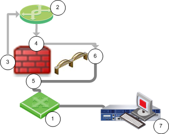
Configuring Single Gateway in Bridge Mode
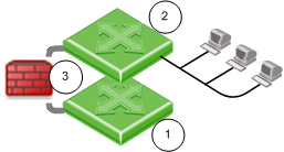
|
Item
|
Description
|
1 and 2
|
Switches
|

|
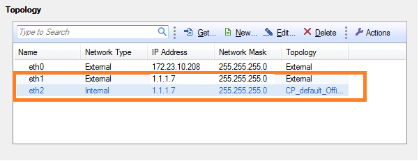
Security Gateway Firewall bridging Layer-2 traffic over the one IP address, with a subnet on each side using the same address.
|
Before you begin, configure a dedicated management interface.
|
Important - Do not configure an IP address on the newly created bridge interface.
|
First you configure the bridge interface. Then you define the bridge topology in SmartDashboard.
To configure a bridge interface in the WebUI:
- In the WebUI navigation tree, select .
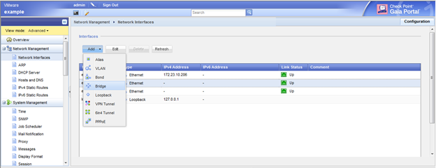
- Click > .
The window opens.
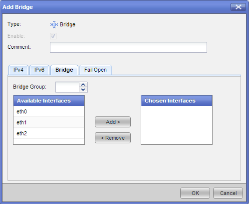
- On the tab, enter or select a ID (unique integer between 1 and 1024).
- Select the interfaces from the list and then click .
- Click .
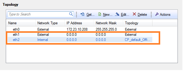
To define the bridge topology:
|
Important - The topology of the bridge ports cannot be automatically calculated, because the bridge ports do not have IP addresses. There are no routes defined on the Security Gateway which include the bridge ports as gateways.
|
You must manually configure the topology for the bridge ports, with the network or group object that represents the networks or subnets behind each port.
Configuring an IP Address for the Bridge
In a bridge deployment with one Security Gateway, you can configure an IP address for the bridge. This is for gateway management from the Security Management Server. The IP address of the bridge is the main address of the gateway. It is the access address for the gateway portals.
The IP address of the bridge must be in the bridged subnet.
Make sure that only the bridge interface has an IP address. The bridge ports must not have IP addresses.
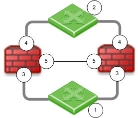
Configuring Gateway Cluster in Bridge Mode
|
Item
|
Description
|
1 and 2
|
Switches
|
|
Security Gateway Firewall bridging Layer-2 traffic
|
3
|
eth1
|
4
|
eth2
|
5
|
eth3 - the ClusterXL Sync interface
|
You can configure cluster gateways for bridge mode in different deployments:
- Active/Standby mode
- Active/Active (STP) mode
Configuring Active/Standby Mode
This is the preferred mode in topologies that support it.
In Active-Standby mode, ClusterXL decides the cluster state. The standby member drops all packets. It does not pass any traffic, including STP/RSTP/MSTP. If there is a failover, the switches are updated by the Security Gateway to forward traffic to the new active member.
If you use this mode, it is best to disable STP/RSTP/MSTP.
To configure Active/Standby mode:
- Configure the cluster.
- Run:
cpconfig - Enter
8, to select . - Confirm:
y - Reboot the cluster member.
- Install Policy.
- Test the cluster state:
cphaprob stat The output should be similar to:
Cluster Mode: High Availability (Active Up, Bridge Mode) with IGMP Membership
Number Unique Address Firewall State (*)
1 (local> 2.2.2.3 Active
2 2.2.2.2 Standby
Configuring Active/Active STP Mode
When you define a bridge interface on a Security Gateway cluster, STP mode is activated by default.
Use STP mode when switches run STP/RSTP/MSTP protocols between them. In this mode, both members are active. The protocol decides which member should handle the traffic. Check Point supports standard technologies of STP. See your vendor documentation to learn how to deploy and configure STP on your network hardware.
Before you begin, install ClusterXL HA on a Gaia computer or appliance, R75.40VS or higher.
To configure STP mode, do these steps on each member of the cluster:
- Configure dedicated management and Sync interfaces.
- Add a bridge interface, as in a single gateway deployment.
Do not configure an IP address on the newly created bridge interface.
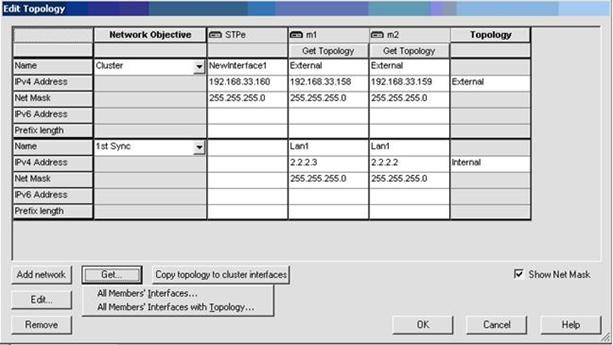
- In SmartDashboard, add the cluster object:
- Open of the cluster object.
- Get the cluster topology.
- Make sure the dedicated management and Sync interfaces are configured.
- Make sure the bridge interface and bridge ports are not in the topology.
Bridge port topology cannot be defined. It is by default.
- Install Policy.
- Test the cluster state:
cphaprob stat The output should be similar to:
Cluster Mode: High Availability (Active Up, Bridge Mode) with IGMP Membership
Number Unique Address Firewall State (*)
1 (local> 2.2.2.3 Active
2 2.2.2.2 Active
Spanning Tree Protocol (STP) Bridge Mode
The Spanning Tree Protocol is an industry standard technology to prevent loops in high-speed switched networks. To use the STP Bridge mode, you must have STP deployed and properly configured on your network. These STP layer-2 protocols are supported:
- 802.1q
- 802.1D
- 802.1s
- 802.1w
- PVST+
See your vendor documentation to learn how to deploy and configure STP on your network hardware.
Cluster Between Four Switches
You can configure a bridged cluster between four switches, in STP mode.
Active/Standby mode is not supported.
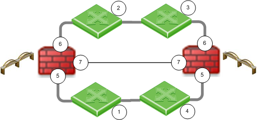
Item
|
Description
|
1, 2, 3, 4
|
Switches
|
|
Security Gateway Firewall bridging Layer-2 traffic
|
5
|
eth1
|
6
|
eth2
|
7
|
eth3 - the ClusterXL Sync interface
|
See also: Link Aggregation with ClusterXL in Layer-2
Routing and Bridges
Security Gateways with a bridge interface can support Layer 3 routing over non-bridged interfaces. If you configure a bridge interface with an IP address for one Security Gateway (not a cluster), the bridge functions as a regular Layer 3 interface. It participates in IP routing decisions on the gateway and supports Layer 3 routing.
- Cluster deployments do not support this configuration.
- You cannot configure the bridge to be the route gateway.
- One Security Gateway can support multiple bridge interfaces, but only one bridge can have an IP address.
- The Security Gateway cannot filter or transmit packets on a bridge interface that it inspected before (double-inspection).
Incoming and outgoing traffic from a Layer-3 management interface is dropped if traversed over a bridge interface. You can make this traffic pass. Disable inspection on the management interface and disable local anti-spoofing.
Item
|
Description
|
1
|
Switch
|
2
|
Router
|
|
Security Gateway Firewall bridging Layer-2 traffic
|
3
|
management interface
|
4
|
eth1
|
5
|
eth2
|
6
|
bridge interface - management traffic drops
|
7
|
Security Management Server
|
Note: This removes inspection from the management interface and could compromise gateway security. If you are unsure whether your environment is safe to use this method, contact Check Point Solution Center.
To configure management over the bridge:
- Open
$PPKDIR/modules/simkern.conf and add: simlinux_excluded_ifs_list=interface name (Create this file if not found.)
Where the value (interface name) is the management interface name.
This excludes the management interface from SecureXL.
- Edit
FWDIR/modules/fwkern.conf.(Create this file if not found.)
Add these lines:
fwx_bridge_use_routing=0
fw_local_interface_anti_spoofing=0
fwlinux_excluded_ifs_list=interface name
Where the value (interface name) is the management interface name.
This disables local Anti-spoofing and bridge routing, and excludes the management interface from security inspection.
- Reboot.
Link State
When one port of a bridge loses its link, the link on the other bridge port goes down too. This lets the switch detect and react to a link failure on the other side of the bridge.
Link state propagation is supported on these Check Point appliance line cards:
- CPAC-4-1C/CPAC-8-1C – copper line cards with igb driver
- CPAC-4-1F – 1Gbe fiber line card with igb driver
- CPAC-4-10F – 10Gbe fiber line card with ixgbe driver
|
Note - From R75.40VS, link state propagation is available as a hotfix, on special request from Check Point Solution Center.
To enable link state propagation contact Check Point technical support.
|
VLANs
When switches are configured with VLANs, VLAN traffic can pass through our bridge in Access mode or in Trunk mode:
- Access mode (VLAN translation) – Bridge is constructed from two VLAN interfaces.
- Trunk mode – Bridge is constructed from two non-VLAN interfaces. The VLAN tag is not removed, and the firewall processes the tagged packet. The traffic passes with the original tag to its destination.
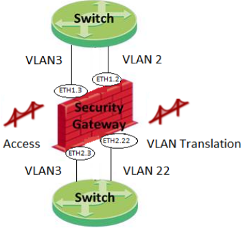
Access Mode VLAN
When the switch is configured in Access Mode, create the bridge from two VLAN interfaces as the slave ports of the bridge. For VLAN translation, use different numbered VLAN interfaces to create the bridge. You can build multiple VLAN translation bridges on the same Security Gateway.
|
Note - VLAN translation is not supported over bridged FONIC (Fail open NIC) ports. See sk85560.
|
To configure VLAN translation:
- Add the VLANs. In the WebUI: .
The window opens. Configure the interfaces of the VLAN.
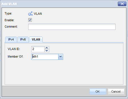
- Open the window and select the VLAN interfaces in the tab.
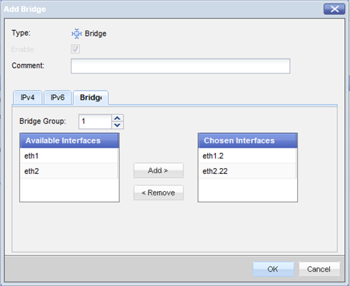
VLAN ID 2 traffic will be translated into VLAN ID 22, and vice versa.
Special Protocols
- Per-VLAN Spanning Tree. PVST is a CISCO proprietary version of STP and maintains a spanning tree instance for each VLAN configured in the network. It uses ISL Trunking and lets a VLAN trunk be forwarded for some VLANs and blocked for others. Because PVST treats each VLAN as a separate network, it can load balance traffic at layer-2. It forwards some VLANs on one trunk and other VLANs on another trunk without causing a Spanning Tree loop.
- Bridge Protocol Data Unit. BPDUs are data messages that are exchanged across the switches within an extended LAN that uses a spanning tree protocol (STP) topology.
When VLAN translation is configured, BPDU frames can arrive with the wrong VLAN number to the ports through the bridge. This mismatch can cause the switch port to enter into blocking mode.
In Active-Standby mode only, there are options to avoid blocking mode.
Disable BPDU forwarding:
- Add tothe line:
net.bridge.bpdu_forwarding = 0 - Reboot.
Block all non IPv4, IPv6 and ARP traffic going through the gateway.
- Add to the line:
fwaccept_unknown_protocol=0 - Reboot.
Trunk Mode
If you configure the switch ports as VLAN trunk, the Check Point bridge should not interfere with the VLANs. To configure bridge with VLAN trunk, create the bridge from two interfaces (no VLAN).
|
Note - VLAN translation is not supported in Trunk mode.
|
If you configure a cluster in Active-Standby mode , CCP monitoring on interfaces may be dropped by the switch when the switch is configured with VLAN tags.
To avoid cpha interfaces active check issues and to solve CCP drops: disable interface monitoring, or add a VLAN to the bridge slave ports.
To disable interface monitoring:
- Log in to the gateway in expert mode.
- Run:
vi $FWDIR/conf/discntd.if - Add the names of the slave interfaces to the file.
- Save the file.
- Reboot.
To add VLAN tags to enable CCP:
Add a non-used VLAN to the switch trunk ports and to the bridge slave interfaces.
- Run:
show bridging group <id>The output lists the bridge interfaces.
- Run:
add interface <listed_bridge_interface> vlan <id>For example, if the show bridging group command outputs:
eth1
eth2
Enter:
add interface eth1 vlan 33
add interface eth2 vlan 33
- On a cluster member, run:
cphaprob -a ifSee that the VLANs are added to the cluster.
Example output:
Required interfaces: 4
Required secured interfaces: 1
Internal UP non sync(non secured), multicast
External UP non sync(non secured), multicast
Lan3 UP sync(secured), multicast
br1 Disconnected non sync(non secured), broadcast
Lan1 UP non sync(non secured), broadcast (Lan1.33 )
Lan2 UP non sync(non secured), broadcast (Lan2.33 )
Virtual cluster interfaces: 2
Internal 10.33.160.1
External 192.168.33.160
Configuring a Dedicated DLP Gateway in Bridge Mode
When setting up a dedicated DLP gateway, Check Point recommends that you configure the DLP gateway as a bridge, so that the DLP gateway is transparent to network routing.
You can deploy DLP in bridge mode, with the requirements described in this section for routing, IP address, and VLAN trunks.
Note the current limitations:
- In an environment with more than one bridge interface, the DLP gateway must not see the same traffic twice on the different interfaces. The traffic must not run from one bridged segment to another.
- Inter-bridge routing is not supported. This includes inter-VLAN routing.
- Routing from the bridge interface to a Layer3 interface, and from Layer3 interface to the bridge, is not supported. Traffic on the bridge interface must run through the bridge or be designated to the DLP gateway.
- If the DLP gateway in bridge mode is behind a cluster, the cluster must be in HA mode.
- If the bridge interface is connected to a VLAN trunk, all VLANs will be scanned by DLP. You cannot exclude specific VLANs.
- Bond High Availability (HA) or Bond Load Sharing (LS) (including Link Aggregation) are not supported in combination with bridge interfaces.
Required Routing in Bridge Mode
There must be routes between the DLP gateway and the required servers:
- Security Management Server
- DNS server
- Mail server, if an SMTP Relay server is configured to work with the gateway
- Active Directory or LDAP server, if configured to work with the gateway
There must be a default route. If this is not a valid route, it must reach a server that answers ARP requests.
If UserCheck is enabled, configure routing between the DLP gateway and the users network.
Configuring Bridge IP Address
The bridge interface can be configured without an IP address, if another interface is configured on the gateway that will be used to reach the UserCheck client and the DLP Portal.
If you do add an IP address to the bridge interface after the Security Gateways are started, run the cpstop and cpstart commands to apply the change.
In Gaia, you must configure an IP address on the bridge interface.
Required VLAN Trunk Interfaces
- A single bridge interface must be configured to bind the DLP gateway for a VLAN trunk.
- If an IP address is configured on the bridge, the IP address must not belong to any of the networks going through the bridge. Users must have routes that run traffic through the bridge interface of the DLP gateway. The gateway handles this traffic and answers to the same VLAN of the original traffic.
- In a VLAN trunk interface, another interface must be configured as the management interface for the required bridge routing.
Virtual System in Bridge Mode
A Virtual System in bridge mode implements native layer-2 bridging. A typical bridge mode scenario incorporates an 802.1q compatible VLAN switch on either side of the VSX Gateway. The Virtual System interfaces do not have IP addresses.
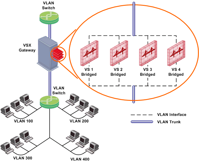
A Virtual System in bridge mode:
- Simplifies virtual network management
- Does not segment an existing virtual network
- Requires manual topology configuration to enforce anti-spoofing
To configure a Virtual System to use bridge mode, define it as a when you first create it. You cannot reconfigure a non-Bridge mode Virtual System to use bridge mode later.
Core Network Security
Many Enterprise environments are based on core networks. Situated adjacent to core network backbone switches, VSX protects the internal network by providing security at layer-2, layer-3 or both. VSX communicates with the core network using the existing infrastructure. With Virtual Systems in the Bridge Mode, VSX can protect departmental networks, while simultaneously preventing network segmentation. In this case, switches are located at the entrance to each department's network.
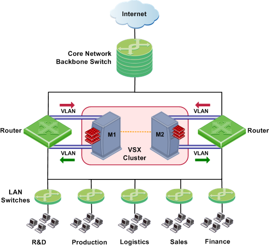
VSX ensures connectivity between the core network and the Internet or external networks, while providing perimeter security. Security can be configured on a per VLAN basis.
Three Layer Hierarchical Model
A three-layer hierarchical model is used in large, high-traffic network environments.
- A core network, with high-speed backbone switches that direct traffic to and from the Internet and other external networks.
- A distribution layer, with routers, for connectivity between the core and the access layer.
- An access layer, with redundant LAN switches, that forward traffic to and from internal networks.
VSX in Active/Standby Bridge mode is incorporated in the distribution layer, enforcing the security policy.
The routers direct external traffic to the appropriate Virtual System through a segregated VLAN. Inspected traffic exits the Virtual System through a separate segregated VLAN, to the routers and then to internal destinations.
Configuring Virtual Systems for Active/Standby Bridge Mode
To configure a Virtual System to use bridge mode, define it as such when you first create the object.
To configure a Virtual System for the Active/Standby Bridge mode:
- In the page of the new Virtual System object, select .
- Click .
The window opens.
- Configure the external and internal interfaces for the Virtual System.
- Select .
The IP address must be unique and on the same subnet as the protected network.
- Click and then click .
Enabling Active/Standby Bridge Mode for a New Member
When you create a new cluster member, enable the cluster options during the first configuration.
- In the Gaia First Time Configuration Wizard page, select .
- From the VSX Gateway CLI, run:
cpconfig- If you enable the Per Virtual System State feature, (required for VSLS), Active/Standby Bridge mode is enabled automatically.
- If you chose not to enable VSLS, an option to enable Active/Standby Bridge mode appears. Enter
y and continue with the gateway configuration.
Enabling Active/Standby Bridge Mode for Existing Members
To enable the Active/Standby Bridge mode on existing Virtual Systems:
- Execute the
cpconfig command. - Enable .
- Reboot the member.
Enabling STP Bridge Mode when Creating Member
When you create a new VSX Gateway to use as a cluster member, configure it as a cluster member when you first define the gateway.
- Run:
cpconfig - At
Would you like to install a Check Point clustering product, enter: y - If prompted to disable Active/Standby Bridge mode, enter:
n - Continue with the cpconfig options as usual.
Enabling the STP Bridge Mode for Existing Members
To enable the STP Bridge mode for existing cluster members:
- Run:
cpconfig - Enable cluster membership for this member.
(If a numerical value appears here, cluster membership has already been enabled).
- Disable ClusterXL for Bridge Active/Standby.
- Reboot the member.
Custom or Override in Bridge Mode
If you used the Custom Configuration template when you created the VSX Gateway, or if you selected the Override Creation Template option, and are creating a Virtual System in bridge mode, manually define the network interfaces.
- Define the external and internal interfaces and links to devices in the table.
- If the cluster with the bridge is on IPSO, select and define the IP address and net mask. Make sure the IP address to be monitored is on a different subnet than the subnet that handles bridge traffic.
VLAN Shared Interface Deployment
In this deployment, each member connects to pair of redundant switches through a VLAN trunk. All Virtual Systems in a given member share the same VLAN trunk.
With Active/Standby bridge mode in High Availability mode, ClusterXL directs traffic to members according to administrator-defined priorities and status. In VSLS deployments, the system distributes the traffic load amongst members according to your VSLS configuration.
VSX Clusters
A VSX cluster has two or more identical, interconnected VSX Gateways for continuous data synchronization and transparent failover. Virtual System Load Sharing (VSLS) enhances throughput by distributing Virtual Systems, with their traffic load, among multiple, redundant machines.
Configuring Clusters for Active/Standby Bridge Mode
To enable the Active/Standby Bridge mode for a cluster:
- Open SmartDashboard.
- From the Network Objects tree, double-click the VSX Cluster object.
The window opens.
- Select > .
- Select .
The Active/Standby Bridge mode loop detection algorithms in ClusterXL is enabled.
Configuring Clusters for STP Bridge Mode
To enable the STP Bridge mode for a cluster:
- Open SmartDashboard.
- From the Network Objects tree, double-click the VSX Cluster object.
The window opens.
- Select > .
- Select .
Separate Interfaces in Bridge Mode
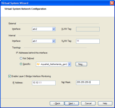
To configure the external and internal interfaces:
- In Virtual System Network Configuration page for the Separate Interfaces template in bridge mode, select the interfaces for the internal and external networks from the list.
If the selected interface is a VLAN interface, enter the same VLAN tag in both the external and internal VLAN Tag fields. This field is not available for non-VLAN interfaces.
- Define the topology for the internal interface:
- Select Not Defined if you do not want to define an IP address.
- Select Specific and then select an IP address definition from the list. IP address definitions can be based on object groups or predefined networks that define the topology.
To create a new IP address definition:
- Select Specific and click New.
- Select Group or Network.
- Enter the group object properties, or network properties, in the window that opens.
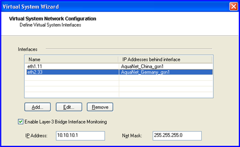
- Select Layer-3 bridge interface monitoring to enable layer 3 network fault detection for this Virtual System.
Enter an IP address and subnet mask for this Virtual System, which continuously monitors the specified network for faults or connectivity issues. The IP address/subnet should define the network on which the Virtual System resides.
- Complete the definition process.
Virtual System Load Sharing (VSLS)
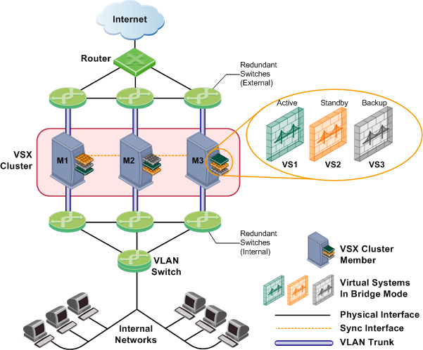
VSX clusters can efficiently balance network traffic load by distributing active Virtual Systems amongst cluster members. This capability is known as Virtual System Load Sharing (VSLS).
The figure below illustrates a deployment scenario with three cluster members, each containing three Virtual Systems. In this configuration, an equalized load sharing deployment might have one active Virtual System on each cluster member.
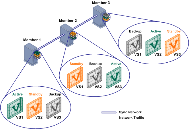
A different member hosts the active peer for each Virtual System. This distribution spreads the load equally amongst the members. Once you create a Virtual System, VSX automatically assigns standby and backup states to the appropriate peers and distributes them among the other cluster members.
In the event that a cluster member fails, VSLS directs traffic destined to affected Virtual Systems to their fully synchronized standby peers, which then become active. At the same time, a backup Virtual Systems switches to standby, and synchronizes with the newly active Virtual System.
In the event that an individual active Virtual System fails, it immediately fails over to its standby peer and one of its backup peers becomes the standby, synchronizing with the newly active peer.
Converting from High Availability to VSLS
To convert an existing high availability cluster to VSLS load sharing:
- Close SmartDashboard.
- On each member:
- Run
cpconfig - Enable the .
- Enable .
- Restart the members:
cpstop and cpstart - On the management server, enter Expert mode.
- Run:
vsx_util convert_cluster - Enter the Security Management Server or Multi-Domain Security Management Domain Management Server IP address.
- Enter the administrator user name and password.
- Enter the VSX cluster name.
- Enter:
LS - At the "Proceed with conversion?" prompt, enter:
y - Select an option to distribute Virtual Systems among members:
- Distribute all Virtual Systems equally.
- Set all Virtual Systems as Active on the same member.
|
Note - You cannot convert a VSX cluster to the VSLS mode if it contains Virtual Systems in the STP Bridge mode or Virtual Routers.
|
|
