Network Management
This chapter includes configuration procedures and examples for network management.
Network Interfaces
Gaia supports these network interface types:
- Ethernet physical interfaces.
- Alias (Secondary IP addresses for different interface types).
- VLAN
- Bond
- Bridge
- Loopback
- 6in4 tunnel
- PPPoE

|
Note - When you add, delete or make changes to interface IP addresses, it is possible that when you use the option in SmartDashboard, the incorrect topology is shown. If this occurs, run cpstopcpstart
|
Interface Link Status
You can see the status of physical and logical interfaces by using the WebUI or the CLI.
To see interface status using the WebUI:
- In the navigation tree, select > .
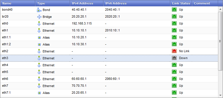
- Double-click an interface to see its parameters.
Link Status
|
Description
|
Grey (Down)

|
The physical interface is disabled (Down).
|
Red (no Link)

|
The physical interface is enabled (up), but Gaia cannot find a network connection.
|
Green (Up)

|
The physical interface is enabled (up) and connected to the network.
|
To see interface status using the CLI, run show interfaces all
Physical Interfaces
This section has configuration procedures and examples for defining different types of interfaces on a Gaia platform.
Gaia automatically identifies physical interfaces (NICs) installed on the computer. You cannot add or delete a physical interface using the WebUI or the CLI. You cannot add, change or remove physical interface cards while the Gaia computer is running.
To add or remove an interface card:
- Turn off the computer.
- Add, remove or replace the interface cards.
- Start the computer.
Gaia automatically identifies the new or changed physical interfaces and assigns an interface name. The physical interfaces show in the list in the WebUI.
Configuring Physical Interfaces - WebUI
This section includes procedures for changing physical interface parameters using the WebUI.
To configure a physical interface:
- In the navigation tree, select > .
- Select an interface from the list and click .
- Select the option to set the interface status to UP.
- On the tab:
- Select to get the IP address from the DHCP server.
Or
- Enter the IP address and subnet mask in the applicable fields.
- On the tab:
- Select to get the IP address from the DHCP server.
Or
- Enter the IP address and mask length in the applicable fields.
- On the tab configure the link speed and duplex setting:
- Select to automatically configure the link speed and duplex setting.
Or
- Select a link speed and duplex setting from the list.
- Enter the hardware MAC address (if not automatically received from the NIC).
Caution: Do not manually change the MAC address unless you are sure that it is incorrect or has changed. An incorrect MAC address can lead to a communication failure.
- Enter a different Maximum Transmission Unit (MTU) value (minimum value=68 - default=1500).
Configuring Physical Interfaces - CLI (interface)
|
|
|
|
Description
|
Configure physical interfaces
|
Syntax
|
set interface <IF>
   ipv4-address <IP>
       mask-length <Mask>
subnet-mask <Mask>
ipv6-address <IP> mask-length <Mask>
ipv6-autoconfig <on | off>
comments <Text>
mac-addr <MAC>
mtu <MTU setting>
state <on | off>
link-speed <Speed_Duplex>
auto-negotiation <on | off>
show interfaces all
|
Parameters
|
interface
|
Configures a physical or virtual interface
|
ipv4-address
ipv6-address
|
Assigns the IPv4 or IPv6 address
|
ipv6-autoconfig
|
If on
|
mask-length
|
Configures IPv4 or IPv6 subnet mask length using CIDR ( /xx) notation
|
subnet-mask
|
Configures IPv4 subnet mask using dotted decimal notation
|
comments
|
Adds free text comments to an interface definition
|
mac-addr
|
Configures the interface hardware MAC address
|
mtu
|
Configure the Maximum Transmission Unit size for an interface
|
state
|
Sets interfaces status to onoff
|
link-speed
|
Configures the interface link speed and duplex status
|
auto-
negotiation
|
Configures automatic negotiation of interface link speed and duplex settings - on off
|
|
|
Parameter Values
|
<IP>
|
IPv4 or IPv6 address
|
<IF>
|
Interface name
|
<Mask>
|
Interface net mask in dotted decimal or CIDR (/xx) notation as applicable
|
<MAC>
|
Manually enter the applicable hardware address
|
<MTU Setting>
|
Integer greater or equal to 68 (Default = 1500)
|
<Speed_Duplex>
|
Enter the link speed in Mbps and duplex status using one of these values:
10M/half
10M/full
100M/half
100M/full
1000M/full
10000M/full
|
|
|
Examples
|
set interface eth2 ipv4-address 40.40.40.1 subnet-mask 255.255.255.0
set interface eth2 mtu 1500
set interface eth2 state on
set interface eth2 link-speed 1000M/full
|
Comments
|
There are some command options and parameters that you cannot do using the WebUI.
|

|
Important - After using CLI commands to add, configure or delete features, you must run the save config
|
Aliases
Interface aliases let you assign more than one IPv4 address to physical or virtual interfaces (bonds, bridges, VLANS and loopbacks). This section shows you how to configure an alias using the WebUI and the CLI.
Configuration using the WebUI
To configure an interface alias using the WebUI:
- In the navigation tree, select > .
- Click > . To change an existing alias interface, select an interface and then click .
- In the (or ) window, select to set the alias interface status to UP.
- On the tab, enter the IPv4 address and subnet mask.
- On the tab, select the interface to which this alias is assigned.
You cannot change the interface for an existing alias definition.
The new alias interface name is automatically created by adding a sequence number to the interface name. For example, the name of first alias added to eth1 is . She second alias added is , and so on.
To delete an interface alias:
- In the navigation tree, select > .
- Select an interface alias and click .
- When the confirmation message shows, click
Configuring Aliases - CLI (interface)
|
|
|
|
Description
|
Configure an alias to a physical interface.
|
Syntax
|
add interface <IF> alias <IP>/<Mask>
delete interface <IF> alias <Alias IF>
|
Parameter Values
|
<IP>
|
IPv4 address
|
<IF>
|
Interface name
|
<Mask>
|
IPv4 subnet mask length using CIDR ( /xx) notation
|
<Alias IF>
|
Interface alias name in the format <IF>:XXXX
|
|
|
Examples
|
add interface eth1 alias 10.10.99.1/24
delete interface eth1 alias eth1:2
|
Comments
|
A new alias interface name is automatically created by adding a sequence number to the original interface name. For example, the name of first alias added to eth1 is . She second alias added is , and so on.
|
|
Important - After using CLI commands to add, configure or delete features, you must run the save config
|
VLAN Interfaces
You can configure virtual LAN (VLAN) interfaces on Ethernet interfaces. VLAN interfaces let you configure subnets with a secure private link to gateways and management servers using your existing topology. With VLAN interfaces, you can multiplex Ethernet traffic into many channels using one cable.
This section shows you how to configure VLAN interfaces using the WebUI and the CLI.
Configuring VLAN Interfaces - WebUI
To configure a VLAN interface using the WebUI:
- In the WebUI navigation tree, select > .
- Click > . To change an existing VLAN interface, select an interface and then click .
- In the (or ) window, select the option to set the VLAN interface to UP.
- and tabs, enter the IP addresses and subnet information as necessary. You can optionally select the option.
- On the tab, enter or select a (VLAN tag) between 2 and 4094.
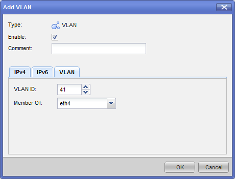
- In the field, select the physical interface related to this VLAN.
|
Note - You cannot change the VLAN ID or physical interface for an existing VLAN interface. To change these parameters, delete the VLAN interface and then create a New VLAN interface.
|
Configuration Using the CLI
This section is a reference for the VLAN interface commands.
|
|
|
|
Description
|
Use these commands to configure bridge interfaces.
|
Syntax
|
add interface <IF> vlan <VLAN ID>
set interface <IF> <VLAN ID>
ipv4-address <IP> mask-length <Length>|subnet-mask<Mask>
ipv6-address <IP> mask-length <Length>
ipv6-autoconfig
delete interface <IF> vlan <VLAN ID>
|
Parameters
|
interface
|
Configure an interface
|
ipv4-address
|
Assign an IPv4 address
|
ipv6-address
|
Assign an IPv6 address
|
ipv6-autoconfig
|
Automatically configure an IPv6 address
|
on
|
Enable automatic configuration
|
off
|
Disable automatic configuration
|
|
|
Values
|
<IF>
|
Physical interface related to this VLAN
|
<VLAN ID>
|
VLAN identifier (integer range 1-4094)
|
<IP>
|
IP address (IPv4 or IPv6)
|
<Length>
|
Mask length (integer value)
|
|
|
Example
|
add interface vlan eth1
set interface eth1.99 ipv4-address 99.99.99.1 subnet-mask 255.255.255.0
set interface eth1.99 ipv6-address 209:99:1 mask-length 64
delete interface eth1 vlan 99
|
|
Important - After using CLI commands to add, configure or delete features, you must run the save config
|
CLI Procedures
To add a new VLAN interface:
Run add interface <IF Name> vlan <VLAN ID>
<IF Name><VLAN ID>
Example:
add interface eth1 vlan 10
To add IP addresses to a VLAN interface:
Run:
set interface <IF Name>.<VLAN ID> ipv4-address <IPv4 Address> [ipv6-address <IPv6 Address>]
<IF Name><VLAN ID><IPv4 Address><IPv6-address>
Examples:
set interface eth1.99 ipv4-address 99.99.99.1 subnet-mask 255.255.255.0
set interface eth1.99 ipv6-address 209:99:1 mask-length 64
To delete a VLAN Interface:
Run:
delete interface <IF Name> vlan <VLAN ID>
Example:
delete interface eth1 vlan 10
Bond Interfaces (Link Aggregation)
Check Point security devices support , a technology that joins multiple physical interfaces into one virtual interface, known as a . The bond interface gives fault tolerance and increases throughput by sharing the load among many interfaces. Check Point devices support the IEEE 802.3ad Link Aggregation Control Protocol (LCAP) for dynamic link aggregation.
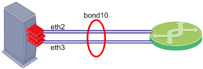
A (also known as a or ) is identified by its (for example: bond1) and is assigned an IP address. The physical interfaces included in the bond are called and do not have IP addresses.
You can define bond interfaces using one of these functional strategies:
- : Gives redundancy when there is an interface or link failure. This strategy also supports switch redundancy. You can configure High Availability to work one of in these modes:
- - Selects the active slave interface sequentially.
- - If the active slave interface goes down, the connection automatically fails over to the primary slave interface. If the primary slave interface is not available, the connection fails over to a different slave.
- : Slave interfaces are active simultaneously. Traffic is distributed among the slave interfaces to maximize throughput. Load Sharing does not support switch redundancy. You can configure load sharing using one of these modes:
- - Selects the active slave interface sequentially.
- - Dynamically uses active slaves to share the traffic load using the LACP protocol. This protocol enables full interface monitoring between the gateway and a switch.
- - Selects the algorithm for slave selection according to the TCP/IP layer.
Configuring Bond Interfaces - WebUI
To configure a bond interface using the WebUI:
- Make sure that the slave interfaces do not have IP addresses.
- On the WebUI page, click .
- For a new bond interface, select > . For an existing Bond interface, double-click the bond interface
- Select the option to activate the bond interface.
- On the and tabs (optional), enter the IP address information.
- On the tab, select or enter a name. This parameter is an integer between 1 and 1024.
- Select slave interfaces from the list and then click .
- Select an ( is the default).
- On the tab, select a ng option and its frequency in milliseconds:
- - This sets the frequency of requests sent to the Media Independent Interface (MMI) to confirm that a slave interface is up. The valid range is 1-5000 ms and the default is 100 ms.
- - This defines the frequency of ARP requests sent to confirm that a slave interface is up. ARP requests are sent to as many as five external MAC addresses.
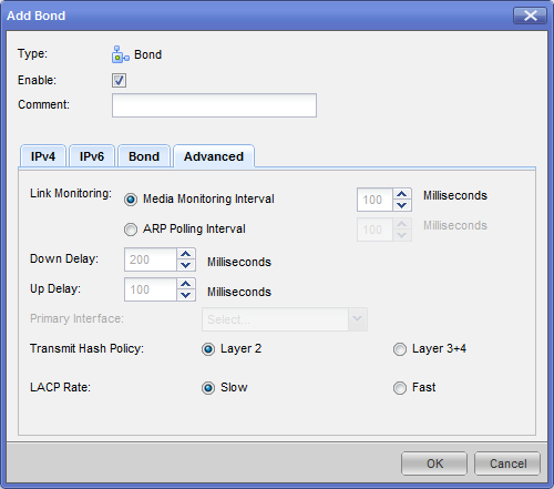
- Select the and intervals in milliseconds. This parameter defines the waiting time, in milliseconds, to confirm the slave interface status before taking the specified action.
- Select the (for Active/Backup bonds only).
- Select the (XOR only). This parameter selects the algorithm for slave selection according to the specified TCP/IP layer.
- Select the . This parameter sets the LACPDU packet transmission rate.
Configuring Bond Interfaces - CLI
When using the CLI, bond interfaces are known as .
When using the CLI to create a bond interface, do these procedures in order:
- Create the bond interface.
- Define the slave interfaces and set them to the UP (on) State.
- Define the bond operating mode.
- Define other bond parameters as necessary.
- Make sure that the bond interface is working correctly.
|
Note - Before running the CLI commands, make sure that the slave interfaces do not have an IP Address already assigned.
|
Link Aggregation - CLI (bonding)
This section is a quick reference for link aggregation commands. The next sections include procedures for different tasks, including explanations of the configuration options.
|
|
|
|
Description
|
Use these commands to configure link aggregation.
|
Syntax
|
add bonding group <Bond ID> interface <Slave>
delete bonding group <Bond ID> interface <Slave>
set bonding group <Bond ID>
primary VALUE
mii-interval VALUE
up-delay VALUE
down-delay VALUE
arp-polling-interval VALUE
mode VALUE
lacp-rate VALUE
xmit-hash-policy VALUE
show bonding group <Bond ID>
show bonding groups
|
Parameters
|
<Bond ID>
|
ID of bond, an integer between 1 and 1024
|
<Slave>
|
Slave interface name
|
primary
|
Name of primary slave interface
|
mii-interval
|
Frequency that the system polls the Media Independent Interface (MII) to get status
|
up-delay
down-delay
|
Waiting time to confirm the slave interface status before taking the specified action (0-5000 ms default = 200 ms).
|
arp-polling-interval
|
Frequency of ARP requests sent to confirm a that slave interface is up
|
mode
|
Bond interface operating mode:
round-robinactive-backupxor 8023AD
|
lacp-rate
|
Sets the LACPDU packet transmission rate
|
xmit-hash-policy
|
Selects the algorithm for slave selection according to the specified TCP/IP layer
|
|
|
Example
|
set bonding group 666 20 eth2
show bonding groups
|
Output
|
Bonding Interface: 20
Bond Configuration
xmit_hash_policy Not configured
down-delay 200
primary Not configured
mode round-robin
up-delay 200
mii-interval 100
lacp_rate Not configured
arp-polling-interval 0
Bond Interfaces
eth2
eth3
|
|
|
|
Important - After using CLI commands to add, configure or delete features, you must run the save config
|
Creating or Deleting a Bond Interface
To add a new bond interface:
Run add bonding group <Bond_id>
<Bond ID>
Example:
add bonding group 777
To delete a bond interface:
- Make sure that you remove all slave interfaces from the bond.
- Run
delete bonding group <bond_id>
|
Important - After using CLI commands to add, configure or delete features, you must run the save config
|
Defining the Bond Operating Mode
You can define bond interfaces using one of these operating modes:
- - Selects the active slave interface sequentially.
- - If the active slave interface goes down, the connection automatically fails over to the primary slave interface. If the primary slave interfaces is not available, the connection fails over to a different slave.
- - Dynamically uses active slaves to share the traffic load using the LACP protocol. This protocol enables full interface monitoring between the gateway and a switch.
- - Selects the algorithm for slave selection according to the TCP/IP layer.
To define the bond operating mode:
Run set bonding group <Bond_id> mode <mode>
- - Bond name
- - One of these key words:
round-robin active-backupxor8023AD
Example:
set bonding group 777 mode round-robin
Defining Slave Interfaces
A bond interface typically contains between two and eight slave interfaces. This section shows how to add and remove a slave interface. The slave interface must not have IP addresses assigned to it.
To add a slave interface to a bond, run:
add bonding group <Bond ID> interface <IF Name>
- - Bond name
- - Slave interface name
Example:
add bonding group 777 interface eth4
|
Note - Do not change the bond state manually. This is done automatically by the bonding driver.
|
To delete a slave interface from a bond, run:
delete bonding group <Bond ID> interface <IF Name>
Example:
delete bonding group 777 interface eth4
|
Note - You must delete all non-primary slave interfaces before you remove the primary slave interface.
|
Defining the Primary Slave Interface
When using the operating mode, the system automatically fails over to the primary slave interface, if available. If the primary interface is not available, the system fails over to a different slave interface. By default, the first slave interface that you define is the primary interface. You must define the slave interfaces and set the operating mode as Active/Backup before doing this procedure.
|
Note - You must delete all non-primary slave interfaces before you remove the primary slave interface.
|
To define the primary slave interface, run:
set bonding group <Bond ID> primary <IF>
- - Bond name
- - Interface name
Example
set bonding group 777 primary eth4
Defining the Media Monitoring Interval
This sets the frequency of requests sent to the Media Independent Interface (MMI) to confirm that a slave interface is up. The valid range is 1-5000 ms and the default is 100 ms.
To configure the MMI, run:
set bonding group <Bond ID> mii-interval <Interval>
- - Bond name
- - Frequency range (1-5000 ms default = 100 ms)
Example:
set bonding group 777 mii-interval 500
To disable MMI monitoring, run:
set bonding group <Bond ID> mii-interval 0
Defining the ARP monitoring interval
This defines the frequency of ARP requests sent to confirm that a slave interface is up. ARP requests are sent to as many as five external MAC addresses.
To configure the ARP interval, run:
set bonding group <Bond ID> arp-polling-interval <Interval>
- - Bond name
- - Frequency (1-5000 ms default = 100 ms)
Example:
Set bonding group 777 arp-polling-interval 500
To disable the ARP interval, run:
set bonding group <Bond ID> arp-polling-interval 0
Defining the UP and Down Delay Times
This parameter defines the waiting time, in milliseconds, to confirm the slave interface status before taking the specified action.
To configure the UP and Down delay times, run:
set bonding group <Bond ID> down-delay <Delay time>
set bonding group <Bond ID> up-delay <Delay time>
- - Bond name
- - Delay (0-5000 ms default = 200 ms)
Example:
set bonding group 777 down-delay 500
Defining Load Sharing Parameters
When using load sharing modes (XOR or 802.3ad), you can configure these parameters:
- - This parameter sets the LACPDU packet transmission rate.
- (802.3ad only) - This parameter selects the algorithm for slave selection according to the specified TCP/IP layer.
To set the LACP rate, run
set bonding group <Bond ID> lacp-rate [slow | fast]
- - Bond name
- - LACPDU packets sent every second
- - LACPDU packets sent every 30 seconds
Example:
set bonding group 777 lacp-rate
To set the Transmit Hash Policy, run:
set bonding group <Bond ID> xmit-hash-policy <layer>
- - Bond name
- - TCP/IP layer
- - Uses XOR of the physical interface MAC address
- - Uses upper layer protocol information
Example:
set bonding group 777 xmit-hash-policy layer2
Making Sure that Link Aggregation is Working
To make sure that a link aggregation is working for a specified bond interface, run this command from the expert mode:
cat /proc/net/bonding/<Bond ID>
Example with output:
cat /proc/net/bonding/bond666
Ethernet Channel Bonding Driver: v3.2.4 (January 28, 2008)
Bonding Mode: fault-tolerance (active-backup)
Primary Slave: None
Currently Active Slave: eth2
MII Status: up
MII Polling Interval (ms): 100
Up Delay (ms): 100
Down Delay (ms): 200
Slave Interface: eth2
MII Status: up
Link Failure Count: 2
Permanent HW addr: 00:50:56:94:11:de
|
Bridge Interfaces
Check Point security devices support bridge interfaces that implement native, Layer-2 bridging. Configuring an interface as a bridge lets network administrators deploy security devices in an existing topology without reconfiguring the existing IP routing scheme. This is an important advantage for large-scale, complex environments. Gaia does not support Spanning Tree Protocol (STP) bridges.
You configure Ethernet interfaces (including aggregated interfaces) on your Check Point security device to work like ports on a physical bridge. The interfaces then send traffic using Layer-2 addressing. You can configure some interfaces as bridge interfaces, while other interfaces on the same device work as layer-3 devices. Traffic between bridge interfaces is inspected at Layer-2. Traffic between two Layer-3 interfaces, or between a bridge interface and a Layer-3 interface is inspected at Layer-3.
This section shows you how to configure bridge interfaces using the WebUI and the CLI.
Configuring Bridge Interfaces - WebUI
To configure a bridge interface in the WebUI:
- In the WebUI navigation tree, select .
- Click > , or select an interface and click .
The (or ) window opens.
- On the tab, enter or select a ID (unique integer between 1 and 1024).
- Select the interfaces from the list and then click .
- Click the or tabs, and then enter the IP addresses and subnet.
Or click .
- Click .
bridging group commands
This is a quick reference for bridge interface commands.
|
|
|
|
Description
|
Use these commands to configure bridge interfaces.
|
Syntax
|
add bridging group <Group Name> [interface <interface>]
delete bridging group <Group Name> interface <interface>
show bridging group <Group Name>
|
Values
|
<Group Name>
|
Name of bridging group
|
<interface>
|
Interface name
|
|
|
Example
|
add bridging group 56 interface eth1
|
|
Important - After using CLI commands to add, configure or delete features, you must run the save config
|
Using the CLI
Bridge interfaces are known as in Gaia clish commands. You can optionally assign an IPv4 or IPv6 address to a bridge interface.
To create a new bridge group:
Run:
> add bridging group <Group Name>
<Group Name>
To add an interface to the bridge group:
Run:
>add bridging group <Group Name> interface <interface>
<interface>
Run this command once for each physical interface included in the bridge interface.
To delete an interface from the bridge group:
Run:
> delete bridging group<Group Name> interface <IF>
Run this command once for each physical interface included in the bridge interface.
To delete a bridge group:
Run:
> delete bridging group <Group Name>
To add or change a bridge interface IP address:
- For an IPv4 IP address, run
> set interface <interface> ipv4-address <IP> subnet-mask <Mask> - For an IPv6 IP address, run
> set interface <interface> ipv6-address <IP> mask-length <Prefix>.<interface>
<IP>
<Mask>
<Prefix>
Example:
set interface eth 1 ipv6-address 3000:40::1 mask-length 64
Loopback Interfaces
You can define a virtual loopback interface by assigning an IPv4 or IPv6 address to the lo
Configuring Loopback Interfaces - WebUI
To configure a loopback interface using the WebUI:
- In the navigation tree, select > .
- Click > . To change an existing loopback interface, select an interface and then click .
- In the (or )window, select to set the loopback interface status to UP.
- On the tab, enter the IPv4 address and subnet mask.
- On the tab, enter the IPv6 address and mask length.
The new loopback interface name is automatically created by adding a sequence number to the string ''. For example, the name of first loopback interface is . She second loopback interface is , and so on.
To delete an interface alias:
- In the navigation tree, select > .
- Select an alias interface and click .
- When the confirmation message shows, click
Configuring Loopback Interfaces - CLI (interface)
Description
|
Configure loopback interfaces
|
Syntax
|
add interface lo loopback <IP>/<Mask>
delete interface lo loopback <IF>
|
Parameters and Values
|
loopback
|
Configures a loopback interface.
|
lo
|
You must use the lo
|
<IP>
|
IPv4 or IPv6 address.
|
<Mask>
|
IPv4 subnet mask or IPv6 mask length using CIDR ( /xx) notation.
|
<IF>
|
Loopback interface name (loopXX
|
|
|
Examples
|
add interface lo loopback 10.10.99.1/24
add interface lo loopback 2010:10:99::1/64
delete interface lo loopback loop01
|
Comments
|
When you create a new loopback interface, Gaia automatically assigns a name in the format loopXXXX
|
|
Important - After using CLI commands to add, configure or delete features, you must run the save config
|
VPN Tunnel Interfaces
Virtual Tunnel Interface. A virtual interface that is a member of an existing, Route Based, VPN tunnel. Each peer Security Gateway has one VTI that connects to the tunnel.
The VPN tunnel and its properties are defined by the VPN community that contains the two gateways. You must define the VPN community and its member Security Gateways before you can create a VTI. To learn more about Route Based VPN, see Route Based VPN in the R76 VPN Administration Guide.
The procedure for configuring a VTI includes these steps:
- Make sure that the VPN Software Blade is enabled and licensed on the applicable Security Gateways.
- Create and configure the Security Gateways.
- Define a VPN community in SmartDashboard that includes the two peer Security Gateways.
- Make Route Based VPN the default option. Do this procedure one time for each Security Management Server.
- Define the VTI using the WebUI or CLI.
- Define Route Based VPN Rules.
- Save the configuration and install the policy.
Defining the VPN Community
You must define the VPN Community and add the member Security Gateways to it before you configure a VPN Tunnel Interface. This section includes the basic procedure for defining a Site to Site VPN Community. To learn more about VPN communities and their definition procedures, see the R76 VPN Administration Guide.
To define a VPN Community for Site to Site VPN:
- In SmartDashboard, click the VPN Communities tab
 in the navigation tree. in the navigation tree. - Right-click and select > or.
- In the window tab, enter the VPN community name.
- Select .
This option automatically adds a rule to encrypt all traffic between gateways in a VPN community.
- On the tab, select member gateways from the list.
For star communities, use the and tabs to do this.
- Configure other community parameters as necessary.
- Save your configuration to the database.
Making Route Based VPN the Default Option
When Domain Based VPN and Route Based VPN are defined for a Security Gateway, Domain Based VPN is active by default. You must do two short procedures to make sure that Route Based VPN is always active.
The first procedure defines an empty encryption domain group for your peer gateways. You do this step one time for each Security Management Server. The second step is to make Route Based VPN the default option for all Security Gateways.
To Define an empty group:
- In the SmartDashboard navigation tree, right-click and then select > .
- In the window, enter a group name in the applicable field.
Do not add members to this group.
To make Route Based VPN the default choice:
- In SmartDashboard, double-click the applicable Security Gateway.
- In the window, click .
- In the section, select and then select the empty group.
Do these steps for each Security Gateway.
Configuring VPN Tunnel Interfaces
You can configure the VPN Tunnel Interfaces using Gaia WebUI or CLI.
Configuring VPN Tunnel Interfaces - WebUI
This section shows you how to configure a VPN Tunnel interface using the WebUI.
To configure a VPN Tunnel Interface:
- In the Gaia WebUI, select I > .
- Click > to create a new interface.
Double-click an existing VTI to change its parameters. - In the window, configure these parameters:
- - Unique tunnel name (integer from 1 to 99)
Gaia automatically adds the prefix 'vpnt - - Remote peer name as defined in the VPN community. You must define the two peers in the VPN community before you can define the VTI. The Peer ID is an alpha-numeric character string.
- - Select or .
- - Defines the local peer IPv4 address (numbered VTI only).
- - Defines the remote peer IPv4 address (numbered VTI only).
- - Local peer interface name (unnumbered VTI only).
Configuring VPN Tunnel Interfaces - CLI (vpn tunnel)
This section shows the CLI commands used to add or delete VPN Tunnel Interfaces.
Description
|
Add or delete a VPN Tunnel Interface (VTI)
|
Syntax
|
add vpn tunnel <Tunnel ID>
type numbered local <Local IP> remote <Remote IP> peer <Peer IP>
type unnumbered peer <Peer ID> dev <IF>
delete vpn tunnel <Tunnel ID
|
Parameters
|
type numbered
|
Defines a numbered VTI that uses a specified, static IPv4 addresses for local and remote connections
|
type unnumbered
|
Defines an unnumbered VTI that uses the interface and the remote peer name to get addresses
|
local
|
Defines the local peer IPv4 address (numbered VTI only)
|
remote
|
Defines the remote peer IPv4 address (numbered VTI only)
|
peer
|
Remote peer name as defined in the VPN community. You must define the two peers in the VPN community before you can define the VTI. The Peer ID is an alpha-numeric character string.
|
dev
|
Defines the interface (unnumbered VTI only)
|
|
|
Parameter
Values
|
<Tunnel ID>
|
Unique tunnel name (integer from 1 to 99)
Gaia automatically adds the prefix 'vpnt
Example: vnpt10
|
<Local IP>
|
Local peer IPv4 address (numbered VTI only) in dotted decimal format
|
<remote IP>
|
Remote peer IPv4 address (numbered VTI only) in dotted decimal format
|
<Peer ID>
|
Remote peer name as defined in the VPN community. You must define the two peers in the VPN community before you can define the VTI. The Peer ID is an alpha-numeric character string.
|
<IF>
|
Local peer interface name (unnumbered VTI only)
|
|
|
Example
|
add vpn tunnel 20 type numbered local 10.10.10.1 remote 20.20.20.1 peer MyPeer
add vpn tunnel 10 type unnumbered peer MyPeer dev eth1
delete vpn tunnel 10
|
|
Important - After using CLI commands to add, configure or delete features, you must run the save config
|
CLI Configuration Procedures for VPN Tunnel Interfaces
To add a numbered VPN Tunnel Interface:
Run:
add vpn tunnel <Tunnel ID> type numbered local <Local IP> remote <Remote IP>
peer <Peer ID>
<Tunnel ID>
Gaia automatically adds the prefix 'vpnttype numberedlocal <Local IP>remote <Remote IP>peer <Peer ID>
To add an unnumbered VPN Tunnel Interface:
Run:
add vpn tunnel <Tunnel ID> type unnumbered local peer <Peer ID>
<Tunnel ID>
Gaia automatically adds the prefix 'vpnttype unnumberedpeer <Peer ID>dev <IF>
To Delete a VPN Tunnel Interface
Run:
delete vpn tunnel <Tunnel ID>
<Tunnel ID>
Gaia automatically adds the prefix 'vpnt
Defining VPN Rules
To make sure that your security rules work correctly with Route Based VPN traffic, you must add directional matching conditions and allow OSPF traffic. This section includes procedures for configuring security rules to do this.
Defining Directional Matching VPN Rules
This section contains the procedure for defining directional matching rules. Directional matching is necessary for Route Based VPN when a VPN community is included in the VPN column in the rule. This is because without bi-directional matching, the rule only applies to connections between a community and an encryption domain (Domain Based Routing).
Name
|
Source
|
Destination
|
VPN
|
Service
|
Action
|
VPN Tunnel
|
Any
|
Any
|
MyIntranet
|
Any
|
accept
|
The directional rule must contain these directional matching conditions:
- Community > Community
- Community > Internal_Clear
- Internal_Clear > Community
is the name of a VPN Community. refers to all traffic from IP addresses to and from the specified VPN community.
Name
|
Source
|
Destination
|
VPN
|
Service
|
Action
|
VPN Tunnel
|
Any
|
Any
|
MyIntranet > MyIntranet
MyIntranet > Internal_Clear
Internal_Clear > MyIntranet
|
Any
|
accept
|
|
Note - It is not necessary to define bidirectional matching rules if the VPN column contains the value.
|
To enable VPN directional matching:
- In SmartDashboard, go to > > > .
- Select the option.
- In SmartDashboard, double-click each member gateway and go to the page.
- Click to update the topology, to include the newly defined VTIs.
- Click .
To define a VPN directional matching rule:
- Double-click the VPN cell in the applicable rule.
- In the window, select .
- Click to define sets of matching conditions.
- In the window, select the source and destination matching conditions.
Do this step for each set of matching conditions.
Defining Rules to Allow OSPF Traffic
One advantage of Route Based VPN is the fact that you can use dynamic routing protocols to distribute routing information between Security Gateways. The OSPF (Open Shortest Path First) protocol is commonly used with VTIs. This section shows you how to allow OSPF traffic in a VPN community.
To learn about configuring OSPF, see the R76 Gaia Advanced Routing Administration Guide.
To Allow OSPF traffic for a VPN Community:
- Using the Gaia WebUI or CLI, add the applicable VPN Tunnel Interfaces to the OSPF configuration page.
- In SmartDashboard, add a rule that allows traffic to the VPN community (or all communities) using the OSPF service.
Name
|
Source
|
Destination
|
VPN
|
Service
|
Action
|
Allow OSPF
|
Any
|
Any
|
MyIntranet
|
ospf
|
accept
|
Completing the VTI Configuration
You must save your configuration to the database and install policies to the Security Gateways before the VPN can be fully functional.
To complete the VTI configuration:
- Save the configuration to the database.
- Install the policy to the gateways.
- Make sure that the VTI tunnel and the rules are working correctly.
ARP
The Address Resolution Protocol (ARP) allows a host to find the physical address of a target host on the same physical network using only the target’s IP address. ARP is a low-level protocol that hides the underlying network physical addressing and permits assignment of an arbitrary IP address to every machine. ARP is considered part of the physical network system and not as part of the Internet protocols.
Configuring ARP- WebUI
To show dynamic ARP entries
- In the WebUI, go to the page.
- If you are in the Static Arp topic, click
To show static ARP entries
- In the WebUI, go to the page.
- If you are in the Dynamic Arp topic, click
To change Static and dynamic ARP parameters
- In the WebUI, go to the page.
- If you are in the Dynamic Arp topic, click
- In the section:
- Enter the This is the maximum number of entries in the arp cache.
Default: 1024, Range: 1024-16384 - Enter the This is the time, in seconds, to keep resolved dynamic ARP entries. If the entry is not referred to and is not used by traffic before the time elapses, it is deleted. Otherwise, a request will be sent to verify the MAC address.
Default: 60 (seconds), Range: 60-86400 (24 hours)
To add a static ARP entry
- In the WebUI, go to the page.
- If you are in the Dynamic Arp topic, click
- Click .
- Enter the of the static ARP entry and the used when forwarding packets to the IP address.
- .
To delete a Static ARP entry
- In the WebUI, go to the page.
- If you are in the Dynamic Arp topic, click
- Select a Static ARP entry
- Click .
To flush all dynamic ARP entries
- In the WebUI, go to the page.
- If you are in the Static Arp topic, click
- Click .
Configuring ARP - CLI (arp)
Description
|
Commands to configure the Address Resolution Protocol (ARP)
|
Syntax
|
To add a static arp entry
add arp static ipv4-address VALUE macaddress VALUE
To delete static and dynamic arp entries
delete arp dynamic all
delete arp static ipv4-address VALUE
To set arp parameters
set arp table validity-timeout VALUE
set arp table cache-size VALUE
To show arp parameters
show arp dynamic all
show arp static all
show arp table validity-timeout
show arp table cache-size
|
Parameters
|
static
|
Configured static arp entries
|
dynamic
|
Configured dynamic arp entries
|
ipv4-address
|
IP Address of a static ARP entry. Range: Dotted-quad ([0-255].[0-255].[0-255].[0-255]).
Default: No Default
|
macaddress
|
The hardware address used when forwarding packets to the given IP address. Range: Six hexadecimal octets separated by colon.
Default: No Default
|
table validity-timeout
|
This is the time, in seconds, to keep resolved dynamic ARP entries. If the entry is not referred to and is not used by traffic before the time elapses, it is deleted. Otherwise, a request will be sent to verify the MAC address.
Default: 60 (seconds), Range: 60-86400 (24 hours)
|
table cache-size
|
This is the maximum number of entries in the arp cache.
Default: 1024, Range: 1024-16384
|
|
|
|
Important - After using CLI commands to add, configure or delete features, you must run the save config
|
DHCP Server
You can configure the Gaia device to be a Dynamic Host Configuration Protocol (DHCP) server. The DHCP server allocates IP addresses and other network parameters to network hosts. DHCP makes it unnecessary to configure each host manually, and therefore reduces configuration errors.
You configure DHCP server subnets on the Gaia device interfaces. A DHCP subnet allocates these network parameters to hosts behind the Gaia interface:
- IPv4 address
- Default Gateway (optional)
- DNS parameters (optional):
- Domain name
- Primary, secondary and tertiary DNS server
This is the general workflow for allocating DHCP parameters to hosts (for the details, see the next section):
- To define a DHCP subnet on a Gaia device interface:
- Enable DHCP on the Gaia network interface.
- Define the network IPv4 address of the subnet on the interface.
- Define an IPv4 address pool.
- Optional: Define routing and DNS parameters for hosts.
- Define additional DHCP subnets on other Gaia interfaces, as needed.
- Enable the DHCP server process.
- Configure the network hosts to use the DHCP server.
Configuring a DHCP Server- WebUI
To allocate DHCP parameters to hosts
- In the tree view, click > .
- In the section, click .
The window opens. You now define a DHCP subnet on an Ethernet interface of the Gaia device. Hosts behind the Gaia interface get IPv4 addresses from address pools in the subnet.
- Select to enable DHCP for the subnet.
- In the tab, enter the of the interface. Click to do this automatically.
- Enter the .
- In the section, click and define the range of IPv4 addresses that the server will assign to hosts.
- Optional: Define a in seconds, for host IPv4 addresses. This is applied only if clients do not request a unique lease time. If you do not enter a value, the configuration default is 43,200 seconds.
- Optional: Define a in seconds, for host IPv4 addresses. This is the longest lease available. If you do not enter a value, the configuration default is 86,400 seconds.
- Optional: Click the tab to define routing and DNS parameters for hosts:
- The IPv4 address of the default gateway for the network hosts
- . The domain name of the network hosts. For example,
example.com - . The DNS server that the network hosts use to resolve hostnames.
- . The DNS server that the network hosts use to resolve hostnames if the primary server does not respond.
- . The DNS server that the network hosts use to resolve hostnames if the primary and secondary servers do not respond.
- Click .
- Optional: Define DHCP subnets on other Gaia interfaces, as needed.
- In the main page, select .
- Click .
The DHCP server on Gaia is now configured and enabled.
You can now configure your network hosts to get their network parameters from the DHCP server on Gaia.
Configuring a DHCP Server - CLI (dhcp)
Description
|
DHCP Server commands allow you to configure the Gaia device as DHCP server for network hosts.
|
Syntax
|
To create DHCP Server subnets:
add dhcp server subnet VALUE
netmask VALUE
include-ip-pool start VALUE end VALUE
exclude-ip-pool start VALUE end VALUE
To change DHCP Server subnet configurations:
set dhcp server subnet VALUE
enable
disable
include-ip-pool VALUE enable
include-ip-pool VALUE disable
exclude-ip-pool VALUE enable
exclude-ip-pool VALUE disable
default-lease VALUE
max-lease VALUE
default-gateway VALUE
domain VALUE
dns VALUE
To delete DHCP Server subnets:
delete dhcp server subnet VALUE
exclude-ip-pool VALUE
include-ip-pool VALUE
To enable or disable the DHCP Server process:
set dhcp server
disable
enable
To view DHCP Server configurations
show dhcp server
all
status
subnet VALUE ip-pools
subnets
|
Parameters
|
Parameter
|
Description
|
subnet VALUE
|
The IPv4 address of the DHCP subnet on an Ethernet interface of the Gaia device. Hosts behind the Gaia interface get IPv4 addresses from address pools in the subnet. For example, 192.0.2.0
|
netmask VALUE
|
The IPv4 subnet mask in CIDR notation. For example,
24
|
start VALUE
|
The IPv4 address that starts the allocated IP Pool range. For example 192.0.2.20
|
end VALUE
|
The IPv4 address that ends the allocated IP Pool range. For example 192.0.2.90
|
include-ip-pool VALUE
|
The range of IPv4 addresses to include in the IP pool. For example 192.0.2.20-192.0.2.90
|
exclude-ip-pool VALUE
|
The range of IPv4 addresses to exclude from the IP pool. For example: 192.0.2.155-192.0.2.254
|
enable
|
Enable the DHCP Server subnet, or the DHCP Server process (depending on the context).
|
disable
|
Disable the DHCP Server subnet, or the DHCP Server process (depending on the context).
|
default-lease VALUE
|
The default lease in seconds, for host IPv4 addresses. This is applied only if clients do not request a unique lease time. If you do not enter a value, the configuration default is 43,200 seconds.
|
max-lease VALUE
|
The maximum lease in seconds, for host IPv4 addresses. This is the longest lease available. If you do not enter a value, the configuration default is 86,400 seconds.
|
default-gateway VALUE
|
The IPv4 address of the default gateway for the network hosts
|
domain VALUE
|
The domain name of the network hosts. For example, example.com
|
dns VALUE
|
The DNS (Domain Name Service) servers that the network hosts will use to resolve hostnames. Optionally, specify a primary, secondary and tertiary server in the order of precedence. For example
192.0.2.101, 192.0.2.102, 192.0.2.103
|
all
|
All DHCP server configuration settings.
|
subnets
|
DHCP Server subnet configuration settings.
|
subnet VALUE ip-pools
|
The IP pools in the DHCP Server subnet, and their status: Enabled or Disabled.
|
status
|
The status of the DHCP Server process: Enabled or disabled.
|
|
|
Example
|
gw-9403be> show dhcp server all
|
Output
|
DHCP Server Enabled
DHCP-Subnet 192.0.2
State Enabled
Net-Mask 24
Maximum-Lease 86400
Default-Lease 43200
Domain example.com
Default Gateway 192.0.2.103
DNS 192.0.2.101, 192.0.2.102, 192.0.2.103
Pools (Include List)
192.0.2.20-192.0.2.90 : enabled
192.0.2.120-192.0.2.150 : disabled
Pools (Exclude List)
192.0.2.155-192.0.2.254 : enabled
DHCP-Subnet 192.0.2.155
State Disabled
Net-Mask 24
Maximum-Lease 86400
Default-Lease 43200
Pools (Include List)
192.0.2.10-192.0.2.99 : enabled
DHCP-Subnet 192.0.2.200
State Disabled
Net-Mask 24
Maximum-Lease 86400
Default-Lease 43200
|
|
|
Hosts and DNS
Host Name
You set the host name (system name) during initial configuration. You can change the name.
Configuring Host Name - WebUI
To show the host name
The host name is in the header of the WebUI.
To change the host name
- Open the page.
- In the section, enter the
- The network name of the Gaia device.
- (optional). For example,
example.com
Configuring Host Name - CLI (hostname)
Description
|
Use this group of commands to configure the host name of your platform.
|
Syntax
|
set hostname VALUE
show hostname
|
|

