Deployment Steps
Use the steps listed below to deploy your AWS![]() Amazon® Web Services. Public cloud platform that offers global compute, storage, database, application and other cloud services. Security Cluster
Amazon® Web Services. Public cloud platform that offers global compute, storage, database, application and other cloud services. Security Cluster![]() Two or more Security Gateways that work together in a redundant configuration - High Availability, or Load Sharing..
Two or more Security Gateways that work together in a redundant configuration - High Availability, or Load Sharing..
Step 1: Prepare Your AWS Account
To prepare your AWS account, do these steps:
-
If you do not already have an AWS account, create one at AWS.
-
Use the region selector in the navigation bar to choose the AWS region, where you want to deploy Check Point CloudGuard Auto Scaling on AWS.
-
Create a key pair in your preferred region.
-
If necessary, request a service limit increase for the AWS resources you are going to use.
You may have to do this, if you have an existing deployment that uses the AWS resources below, and you may exceed the default limit with this deployment.
The resources that may need a service limit increase are:
-
Number of On-demand EC2 instances.
-
Number of Elastic IP addresses.
-
Number of VPCs for each region.
-
By default, this Deployment guide uses c5.xlarge for the Security Gateways.
Deployment minimum permissions
For a successful deployment, the relevant IAM policy must have minimum permissions set configured below.
In the AWS VPC![]() AWS Virtual Private Cloud. A private cloud that exists in the public cloud of Amazon. It is isolated from other Virtual Networks in the AWS cloud. Console navigate to IAM service, select the relevant IAM policy and copy/paste this text:
AWS Virtual Private Cloud. A private cloud that exists in the public cloud of Amazon. It is isolated from other Virtual Networks in the AWS cloud. Console navigate to IAM service, select the relevant IAM policy and copy/paste this text:
{
    "Version": "2012-10-17",
    "Statement": [
        {
            "Sid": "Permissions",
            "Effect": "Allow",
            "Action": [
                "cloudformation:CreateStack",
                "cloudformation:DeleteStack",
                "cloudformation:DescribeStacks",
                "cloudformation:ListStackResources",
                "cloudformation:ValidateTemplate",
                "ec2:AllocateAddress",
                "ec2:AssociateAddress",
                "ec2:AssociateRouteTable",
                "ec2:AttachInternetGateway",
                "ec2:AttachNetworkInterface",
                "ec2:AuthorizeSecurityGroupEgress",
                "ec2:AuthorizeSecurityGroupIngress",
                "ec2:CreateInternetGateway",
                "ec2:CreateLocalGatewayRouteTable",
                "ec2:CreateNetworkInterface",
                "ec2:CreateRoute",
                "ec2:CreateRouteTable",
                "ec2:CreateSecurityGroup",
                "ec2:CreateSubnet",
                "ec2:CreateTags",
                "ec2:CreateVpc",
                "ec2:DeleteInternetGateway",
                "ec2:DeleteNetworkInterface",
                "ec2:DeleteRoute",
                "ec2:DeleteRouteTable",
                "ec2:DeleteSecurityGroup",
                "ec2:DeleteSubnet",
                "ec2:DeleteVpc",
                "ec2:DescribeAccountAttributes",
                "ec2:DescribeAddresses",
                "ec2:DescribeAvailabilityZones",
                "ec2:DescribeInstanceAttribute",
                "ec2:DescribeInstanceTypes",
                "ec2:DescribeInstances",
                "ec2:DescribeInternetGateways",
                "ec2:DescribeKeyPairs",
                "ec2:DescribeNetworkAcls",
                "ec2:DescribeNetworkInterfaces",
                "ec2:DescribeRegions",
                "ec2:DescribeRouteTables",
                "ec2:DescribeSecurityGroups",
                "ec2:DescribeSubnets",
                "ec2:DescribeTags",
                "ec2:DescribeVolumes",
                "ec2:DescribeVpcAttribute",
                "ec2:DescribeVpcClassicLink",
                "ec2:DescribeVpcClassicLinkDnsSupport",
                "ec2:DescribeVpcs",
                "ec2:DetachInternetGateway",
                "ec2:DetachNetworkInterface",
                "ec2:DisassociateAddress",
                "ec2:DisassociateRouteTable",
                "ec2:ModifyNetworkInterfaceAttribute",
                "ec2:ModifySubnetAttribute",
                "ec2:ModifyVpcAttribute",
                "ec2:ReleaseAddress",
                "ec2:RevokeSecurityGroupEgress",
                "ec2:RunInstances",
                "ec2:TerminateInstances",
                "iam:AddRoleToInstanceProfile",
                "iam:AttachRolePolicy",
                "iam:CreateInstanceProfile",
                "iam:CreatePolicy",
                "iam:CreateRole",
                "iam:DeleteInstanceProfile",
                "iam:DeletePolicy",
                "iam:DeleteRole",
                "iam:DeleteRolePolicy",
                "iam:DetachRolePolicy",
                "iam:GetInstanceProfile",
                "iam:GetPolicy",
                "iam:GetPolicyVersion",
                "iam:GetRole",
                "iam:ListAttachedRolePolicies",
                "iam:ListInstanceProfilesForRole",
                "iam:ListPolicyVersions",
                "iam:ListRolePolicies",
                "iam:PassRole",
                "iam:PutRolePolicy",
                "iam:RemoveRoleFromInstanceProfile"
            ],
            "Resource": "*"
        }
    ]
}{
"Version": "2012-10-17",
"Statement": [
{
"Sid": "Permissions",
"Effect": "Allow",
"Action": [
"cloudformation:CreateStack",
"cloudformation:DeleteStack",
"cloudformation:DescribeStacks",
"cloudformation:ListStackResources",
"cloudformation:ValidateTemplate",
"ec2:AllocateAddress",
"ec2:AssociateAddress",
"ec2:AssociateRouteTable",
"ec2:AuthorizeSecurityGroupEgress",
"ec2:AuthorizeSecurityGroupIngress",
"ec2:CreateNetworkInterface",
"ec2:CreateRoute",
"ec2:CreateSecurityGroup",
"ec2:CreateTags",
"ec2:DeleteNetworkInterface",
"ec2:DeleteRoute",
"ec2:DeleteSecurityGroup",
"ec2:DescribeAddresses",
"ec2:DescribeInstanceAttribute",
"ec2:DescribeInstanceTypes",
"ec2:DescribeInstances",
"ec2:DescribeKeyPairs",
"ec2:DescribeNetworkInterfaces",
"ec2:DescribeRouteTables",
"ec2:DescribeSecurityGroups",
"ec2:DescribeSubnets",
"ec2:DescribeTags",
"ec2:DescribeVolumes",
"ec2:DescribeVpcs",
"ec2:DetachNetworkInterface",
"ec2:DisassociateAddress",
"ec2:DisassociateRouteTable",
"ec2:ModifyNetworkInterfaceAttribute",
"ec2:ReleaseAddress",
"ec2:RevokeSecurityGroupEgress",
"ec2:RunInstances",
"ec2:TerminateInstances",
"iam:AddRoleToInstanceProfile",
"iam:AttachRolePolicy",
"iam:CreateInstanceProfile",
"iam:CreatePolicy",
"iam:CreateRole",
"iam:DeleteInstanceProfile",
"iam:DeletePolicy",
"iam:DeleteRole",
"iam:DeleteRolePolicy",
"iam:DetachRolePolicy",
"iam:GetInstanceProfile",
"iam:GetPolicy",
"iam:GetPolicyVersion",
"iam:GetRole",
"iam:ListAttachedRolePolicies",
"iam:ListInstanceProfilesForRole",
"iam:ListPolicyVersions",
"iam:ListRolePolicies",
"iam:PutRolePolicy",
"iam:RemoveRoleFromInstanceProfile"
],
"Resource": "*"
},
{
"Sid": "IAMPassRole",
"Effect": "Allow",
"Action": "iam:PassRole",
"Resource": "*",
"Condition": {
"StringEquals": {
"iam:PassedToService": "ec2.amazonaws.com"
}
}
}
]
}Step 2: Subscribing to Check Point CloudGuard Network
To subscribe to Check Point CloudGuard Network, do these steps:
-
Log in to AWS Marketplace.
-
Select one of these licensing options for Check Point CloudGuard Security Gateways:
-
Select Continue to subscribe.
-
To confirm that you accept the AWS Marketplace license agreement, select Accept Terms.
Step 3: Deploying the Check Point Security Cluster
Use one of these options to deploy the Check Point Security Cluster.
Manually Deploying a Check Point Cluster in AWS
If you have used the CloudFormation templates to deploy the Check Point Cluster in AWS, skip to Configuring a Check Point Cluster in SmartConsole![]() Check Point GUI application used to manage a Check Point environment - configure Security Policies, configure devices, monitor products and events, install updates, and so on..
Check Point GUI application used to manage a Check Point environment - configure Security Policies, configure devices, monitor products and events, install updates, and so on..
Create an IAM role
In this step, we create an IAM role and an Instance Profile. When you launch the Check Point Cluster Members, you would pass them this role. This allows the Cluster Members to automatically make changes in the VPC environment if a cluster failover occurs.
|
|
Note - Only privileged AWS users can create IAM roles. |
-
Go to Policies > select Create policy
-
Select Json and paste the following (to allow access to all accounts and VPCs):
CopyExample of a JSON script
{
  "Version": "2012-10-17",
  "Statement": [
    {
      "Action": ["ec2:DescribeRouteTables",
        "ec2:ReplaceRoute",
        "ec2:AssignPrivateIpAddresses",
        "ec2:DescribeNetworkInterfaces",
        "ec2:CreateRoute"
        ],
      "Effect": "Allow",
      "Resource": "*"
    }
  ]
} -
Go to Roles > select Create role.
-
In the Choose a use case, select EC2.:
-
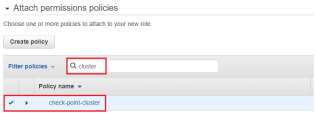
In Attach permissions policies, locate and select the policy you created in the previous steps:

Creating the VPC Environment
These steps give a high-level description about how to create a VPC environment.
-
Create a VPC.
-
Create an Internet Gateway in the VPC.
-
Create the external and internal subnets.
-
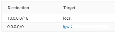
Create a route table and associate it with the external subnet, add a default route and point it to the Internet Gateway:
The Check Point Security Gateway![]() Dedicated Check Point server that runs Check Point software to inspect traffic and enforce Security Policies for connected network resources. can enforce a more sophisticated Security Policy
Dedicated Check Point server that runs Check Point software to inspect traffic and enforce Security Policies for connected network resources. can enforce a more sophisticated Security Policy![]() Collection of rules that control network traffic and enforce organization guidelines for data protection and access to resources with packet inspection., making the VPC security groups redundant. This procedure explains how to create a permissive VPC security group to prevent a possible conflict between the VPC security groups and the Check Point security policy.
Collection of rules that control network traffic and enforce organization guidelines for data protection and access to resources with packet inspection., making the VPC security groups redundant. This procedure explains how to create a permissive VPC security group to prevent a possible conflict between the VPC security groups and the Check Point security policy.
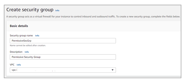
To create a new security group:
-
Go to EC2.
-
Select Security Groups in the left menu.
-
Click Create Security Group.
-
In the Group name field, enter the group name - PermissiveSecGrp.
-
In the Description field, enter: Permissive Security Group.
-
In the VPC field, select the VPC.
-
Click Yes > select Create.
-
-
Create a new rule
 Set of traffic parameters and other conditions in a Rule Base (Security Policy) that cause specified actions to be taken for a communication session. for this Security Group that accepts all traffic from any source address:
-
In the Security Groups list, select the new PermissiveSecGrp.
-
Go to the Inbound Rules tab > click Edit inbound rules.
-
Create a new rule that accepts all traffic from any source address.
-
Click Save Rules.

-

Launch the Cluster Members
Launch a Check Point CloudGuard Network Security instance from the AWS marketplace.
Use these settings:
-
Choose an Instance Type.
-
In the Network field, select your VPC
-
In the Subnet field, select your external subnet.
-
In the IAM role field, select the IAM role you created in the previous steps (refer to section "Create an IAM role" above).

Note - To assign the IAM role to the instance, it is necessary to have special IAM privileges.
For more information, see Granting Permission to Launch EC2 Instances with IAM Roles ("iam:PassRole" Permission).
-
In the Network interfaces section > Primary IP field, enter the member's external private IP address (in our example - 10.0.0.20).
-
When prompted to select a Security Group, use the permissive group you created in the previous steps (refer to section Creating the VPC Environment).
-
Launch the instance
-
After the instance starts, go to EC2 > Network Interfaces > Create network interface.
-
Enter the necessary information:
- Description: "Internal interface"
- Subnet: select the subnet 10.0.1.0/24 (in our example)
- Private IP: 10.0.1.20 (in our example)
- Security Group: select the permissive group created in the previous steps (refer to section Creating the VPC Environment above - "To create a new security group")
- Description: "Internal interface"
-
Attach the interface to the Cluster Member
Security Gateway that is part of a cluster. instance -
To add additional interfaces, repeat the above steps.
-
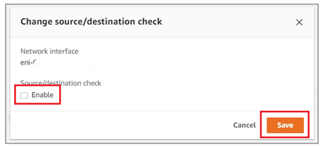
Right-click on all interfaces that you created and uncheck the source/destination check Enable:
-
Allocate an elastic IP address, or select an available one.
-
Associate the elastic IP address with the external private IP address of the instance (in our example - 10.0.0.20). We use this IP address to manage the Cluster Member.
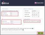
Check Point First Time Configuration Wizard
Do these steps from vSEC Gateway for Amazon Web Services Getting Started Guide, "Installing and Configuring the vSEC Gateway":
-
Enter password for admin user.
-
Enter an Activation Key (it is used later in SmartConsole to establish trust with the Cluster Member. See Step 5: Configuring a Check Point Cluster in SmartConsole
-
Select the checkbox Enable cluster membership for this gateway.
-
Click Go.

Repeat the above steps to launch a second Cluster Member instance.
On Member A (but not on Member B):
-
Add a secondary private IP address to the External interface
-
Assign another elastic IP address to the External interface (this IP address is used as the Cluster public IP address)
-
Add a secondary private IP address to the internal interface.
Deploying Cluster CloudFormation Template
To launch the Security Cluster template into your AWS account, click here, and find Security Cluster.
|
|
Notes -
|
Parameters for Deploying a Security Cluster into a New VPC
VPC Network Configuration:
|
Parameter Name |
Default Value |
Description |
|---|---|---|
|
|
10.0.0.0/16 |
The CIDR block for the VPC |
|
|
Requires Input |
The availability zone in which to deploy the cluster. |
|
|
10.0.10.0/24 |
The external subnet of the cluster. The cluster's public IPs will be generated from this subnet. |
|
|
10.0.11.0/24 |
The internal subnet of the cluster. The cluster's private IPs will be generated from this subnet. |
EC2 Instance Configuration:
|
Parameter Name |
Default Value |
Description |
|---|---|---|
|
|
Check-Point-Cluster |
The name tag of the Security Gateway instances (optional). |
|
|
c5.xlarge |
The instance type of the Security Gateway. |
|
|
Requires input |
The EC2 Key Pair to allow SSH access to the instance. |
|
|
True |
Allocate an Elastic IP for each cluster member, in addition to the shared cluster Elastic IP. |
|
|
100 |
|
|
|
alias/aws/ebs |
KMS or CMK key Identifier - Use key ID, alias or ARN. Key alias should be prefixed with 'alias/' (e.g. for KMS default alias 'aws/ebs' - insert 'alias/aws/ebs'). |
|
|
False |
Enable SSH connection over AWS web console, see sk163494. |
|
|
Optional |
A predefined IAM role to attach to the cluster profile. |
Check Point Settings:
|
Parameter Name |
Default Value |
Description |
|---|---|---|
|
|
"version"-"license" |
The license to use for the Security Gateways. By default, "version" points to the current recommended version and "license" is set to NGTX. |
|
|
/etc/cli.sh |
Change the admin shell to enable advanced command line configuration. |
|
|
Optional |
The administrator password hash. Run this command to get the password hash:
|
|
|
Requires input |
The Secure Internal Communication key creates trusted connections between Check Point components. Choose a random string consisting of at least 8 alphanumeric characters. |
Quick Connect to Smart-1 Cloud:
Smart-1 Cloud (Check Point’s management server as a Service) is a recommended option to start using CloudGuard Network Security Gateways.
|
Parameter Name |
Default Value |
Description |
|---|---|---|
Smart-1 Cloud Token for member A
|
Requires input |
Follow the instructions in sk180501 to create tokens for each member and paste them into the applicable fields. |
|
|
Requires input |
Follow the instructions in sk180501 to create tokens for each member and paste them into the applicable fields. |
Advanced Settings:
|
Parameter Name |
Default Value |
Description |
|---|---|---|
|
|
Optional |
Name tag prefix of the resources. |
|
|
Optional |
The host name will be appended with member-a/b accordingly. |
|
|
True |
Automatically download Blade Contracts and other important data. Improve product experience by sending data to Check Point. |
|
|
Optional |
An optional script with semicolon (;) separated commands to run on the initial boot. |
|
|
169.254.169.123 (Optional) |
Option to input a different Primary NTP server. |
|
|
0.pool.ntp.org (Optional) |
Option to input a different Secondary NTP server. |
Parameters for Deploying a Security Cluster into an Existing VPC
VPC Network Configuration:
|
Parameter Name |
Default Value |
Description |
|---|---|---|
|
|
Requires Input |
The ID of your existing VPC. |
|
|
Requires Input |
The public subnet of the cluster. The cluster's public IPs will be generated from this subnet. |
|
|
Requires Input |
The private subnet of the cluster. The cluster's private IPs will be generated from this subnet. |
|
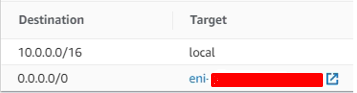
|
Optional |
Set 0.0.0.0/0 route to the Active Cluster member instance in this route table (e.g. rtb-12a34567). Route table cannot have an existing 0.0.0.0/0 route. If empty - traffic will not be routed through the Security Cluster, this requires manual configuration in the Route Table. |
EC2 Instance Configuration:
|
Parameter Name |
Default Value |
Description |
|---|---|---|
|
|
Check-Point-Cluster |
The name tag of the Security Gateway instances (optional). |
|
|
c5.xlarge |
The instance type of the Security Gateway. |
|
|
Requires input |
The EC2 Key Pair to allow SSH access to the instance. |
|
|
True |
Allocate an Elastic IP for each cluster member, in addition to the shared cluster Elastic IP. |
|
|
100 |
|
|
|
alias/aws/ebs |
KMS or CMK key Identifier - Use key ID, alias or ARN. Key alias should be prefixed with 'alias/' (e.g. for KMS default alias 'aws/ebs' - insert 'alias/aws/ebs'). |
|
|
False |
Enable SSH connection over AWS web console, see sk163494. |
|
|
Optional |
A predefined IAM role to attach to the cluster profile. |
Check Point Settings:
|
Parameter Name |
Default Value |
Description |
|---|---|---|
|
|
"version"-"license" |
The license to use for the Security Gateways. By default, "version" points to the current recommended version and "license" is set to NGTX. |
|
|
/etc/cli.sh |
Change the admin shell to enable advanced command line configuration. |
|
|
Optional |
The administrator password hash. Run this command to get the password hash:
|
|
|
Requires input |
The Secure Internal Communication key creates trusted connections between Check Point components. Choose a random string consisting of at least 8 alphanumeric characters. |
Quick Connect to Smart-1 Cloud:
Smart-1 Cloud (Check Point’s management server as a Service) is a recommended option to start using CloudGuard Network Security gateways.
|
Parameter Name |
Default Value |
Description |
|---|---|---|
Smart-1 Cloud Token for member A
|
Requires input |
Follow the instructions in sk180501 to create tokens for each member and paste them into the applicable fields. |
|
|
Requires input |
Follow the instructions in sk180501 to create tokens for each member and paste them into the applicable fields. |
Advanced Settings:
|
Parameter Name |
Default Value |
Description |
|---|---|---|
|
|
Optional |
Name tag prefix of the resources. |
|
|
Optional |
The host name will be appended with member-a/b accordingly. |
|
|
True |
Automatically download Blade Contracts and other important data. Improve product experience by sending data to Check Point. |
|
|
Optional |
An optional script with semicolon (;) separated commands to run on the initial boot. |
|
|
169.254.169.123 (Optional) |
Option to input a different Primary NTP server. |
|
|
0.pool.ntp.org (Optional) |
Option to input a different Secondary NTP server. |
Step 4: Deploy the Check Point Security Management Server
We recommend you to use Smart-1 Cloud (Check Point's management server as a Service) to manage CloudGuard Network Security Gateways.
Refer to sk180501 for step-by-step instructions for connecting CloudGuard Network Public Cloud Gateways to Smart-1 Cloud management.
You can also use one of these options to deploy the Check Point Security Management Server.
-
Use the existing on-premises Security Management Server or existing Security Management Server
Check Point Single-Domain Security Management Server or a Multi-Domain Security Management Server. in AWS.
Note - The Security Management Server must be version R81.20 or higher.
-
Deploy a new Security Management Server
Dedicated Check Point server that runs Check Point software to manage the objects and policies in a Check Point environment within a single management Domain. Synonym: Single-Domain Security Management Server. with the Management CloudFormation template (see sk130372).
Step 5: Configuring a Check Point Cluster in SmartConsole
-
Connect with SmartConsole to Security Management Server / Domain Management Server.
-
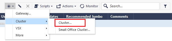
Click on New > select Cluster
-
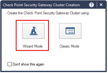
Click Wizard Mode.
-
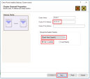
Define the cluster's general properties:
-
In the Cluster Name field, enter the desired name for cluster object (in our example - Cluster1).
-
In the Cluster IPv4 Address field, enter the cluster's external private IP address (in our example - 10.0.0.10).
-
In the Choose the Cluster's Solution list, select Check Point ClusterXL and High Availability.
-
Click Next.
-
-
Define Cluster Members:
-
Member A:
-
Click Add > select New Cluster Member.
-
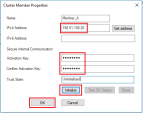
In the Name field, enter the desired member's name (in our example: Member_A).
-
In the IPv4 Address field, enter the member's Elastic IP address (in our example: 198.51.100.20).
-
In the Activation Key field, enter the activation key you have created earlier (refer to section "Check Point First Time Configuration Wizard".
-
Click Initialize.
-
Click OK
-
-
Member B:
-
Click Add > select New Cluster Member.
-
In the Name field, enter the desired member's name (in our example - Member_B).
-
In the IPv4 Address field, enter the member's Elastic IP address (in our example - 198.51.100.30).
-
In the Activation Key field, enter the activation key you have created earlier (refer to section "Check Point First Time Configuration Wizard".
-
Click Initialize.
-
Click OK

-
-
After adding both Cluster Members, click Next.
-
-
To start configuring the topology of the cluster, click Next.
-
Configure the Internal Virtual IP address (in our example:
10.0.1.10 / 255.255.255.0).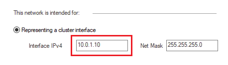
-
Click Next.
-
Configure the External Virtual IP address (in our example:
10.0.0.10 / 255.255.255.0).
-
Click Next.
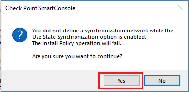
A warning appears that synchronization network was not defined.
Click Yes.
-
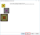
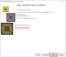
The Cluster definition wizard is now complete.
Select the checkbox Edit Cluster's Properties > click Finish.
-
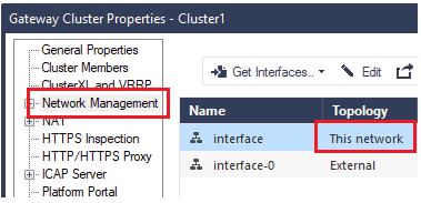
Cluster properties window opens.
Go to Network Management > double click This Network.
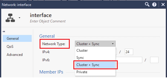
-
Choose Cluster + Sync for Network Type.
-
On each Network interface, click Edit and disable Anti-Spoofing.
-
Verify the settings: close cluster object properties OK.
-
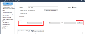
In R82 and higher, after configuring the cluster object and cluster members, you must change the Hardware type of the Security Gateways object that report to the Security Management Server.
For that:
-
In SmartConsole, double-click the cluster object to open its properties.
-
On the General Properties page, in the Platform section, click Get.
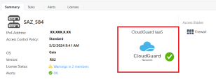
The value in the Hardware field must change from Open Server to CloudGuard IaaS.
-
Click OK to save the changes and close cluster object properties.
As a result, on the Summary tab of this cluster object, a CloudGuard Network logo with a green mark is displayed.
-
-
Install policy on the cluster members.


Step 6: Configure NAT Rules
In SmartConsole, create the NAT rules below to provide Internet connectivity from the internal subnets:
|
No. |
Original Source |
Original Destination |
Original Services |
Translated Source |
Translated Destination |
Translated Services |
Install On |
Comments |
|---|---|---|---|---|---|---|---|---|
| 1 |
Virtual Private Cloud |
Virtual Private Cloud |
*Any |
= Original |
= Original |
= Original |
Cluster object |
Avoid NAT in the Virtual Private Cloud |
| 2 |
App-subnet |
App-subnet |
*Any |
= Original |
= Original |
= Original |
Cluster object |
|
| 3 |
App-subnet |
*Any |
*Any |
App-subnet (hidden address) |
= Original |
= Original |
Cluster object |
|
| 4 |
Web-subnet |
Web-subnet |
*Any |
= Original |
= Original |
= Original |
Cluster object |
|
| 5 |
Web-subnet |
*Any |
*Any |
Web-subnet (hidden address) |
= Original |
= Original |
Cluster object |
|
|
|
Notes about NAT rules: -
|
For each internal subnet, create a network object:
|
Step |
Description |
|---|---|
| 1 |
Double-click the Web-subnet object. The Web-subnet object window shows. |
| 2 | Select the NAT tab > Add automatic address translation rules. |
| 3 | In the Translation method field, select Hide > Hide Behind Gateway. |
| 4 | In the Install on Gateway field, select the cluster object. |
| 5 |
Click OK. This creates the automatic NAT rules. |
| 6 | Install the applicable Access Control Policy on the cluster object. |
Step 7: Post Deployment - Add Route to Active Member
Create a route table and associate it with the internal subnet, add a default route and point it to Active member's internal interface:
Step 8: Reviewing and Testing the Deployment
-
Use the cphaprob state command and the cphaprob -a if command on each Cluster Member to validate that the cluster is operating correctly.
Output of cphaprob state command on both Cluster Member must show identical information (except the "(local)" string).
Example:
[Expert@HostName:0]# cphaprob state
Cluster Mode:   High Availability (Active Up) with IGMP Membership
Number     Unique Address  Assigned Load   State
1 (local)  10.0.1.20       0%              Active
2          10.0.1.30       100%            Standby
-
Simulate a cluster failover.
Examples:
-
Shut down the internal interface of the Active Cluster Member and run:
clusterXL_admin down -
Reboot the Active Cluster Member instance form the AWS console.
After a few seconds, the second Cluster Member reports itself as the Active member.
Go to the AWS Console and confirm that:
- All secondary private IP addresses that were assigned to the 1st member are now assigned to 2nd member
- In all routing tables associated with internal subnets in the VPC, the default route is pointing to the internal interfaces of the member that has taken over.
Note - You might need to refresh the AWS Console to see the changes.
-
-
Verify that the Active Cluster Member is the instance that was deployed with the secondary private IP addresses:
- Open the Amazon EC2 console.
- In the left navigation pane, select Instances.
- Select the Active Cluster Member.
- In the Description tab, verify that there are two private IP addresses in the Secondary private IPs field.
If not, simulate a cluster failover as described in step 2.