Deployment Steps of Cloud Firewall for AWS Auto Scaling Groups
Use the steps listed below to deploy your Cloud Firewall for AWS![]() Amazon® Web Services. Public cloud platform that offers global compute, storage, database, application and other cloud services. Auto Scaling Groups.
Amazon® Web Services. Public cloud platform that offers global compute, storage, database, application and other cloud services. Auto Scaling Groups.
Step 1: Preparing Your AWS Account
To prepare your AWS account, do these steps:
-
If you do not already have an AWS account, create one at AWS.
-
Use the region selector in the navigation bar to choose the AWS region, where you want to deploy Check Point Cloud Firewall Auto Scaling on AWS.
-
Create a key pair in your preferred region.
-
If necessary, request a service limit increase for the AWS resources you are going to use.
You may have to do this, if you have an existing deployment that uses the AWS resources below, and you may exceed the default limit with this deployment.
The resources that may need a service limit increase are:
-
Number of On-demand EC2 instances.
-
Number of Elastic IP addresses.
-
Number of VPCs for each region.
-
Number of Network Load Balancers.
-
Number of Application Load Balancers.
By default, this Deployment guide uses c5.xlarge for the Cloud Firewall Gateways and m5.xlarge for the Security Management Server![]() Dedicated Check Point server that runs Check Point software to manage the objects and policies in a Check Point environment within a single management Domain. Synonym: Single-Domain Security Management Server..
Dedicated Check Point server that runs Check Point software to manage the objects and policies in a Check Point environment within a single management Domain. Synonym: Single-Domain Security Management Server..
Deployment minimum permissions
For a successful deployment, the relevant IAM policy must have minimum permissions set configured below.
In the AWS VPC![]() AWS Virtual Private Cloud. A private cloud that exists in the public cloud of Amazon. It is isolated from other Virtual Networks in the AWS cloud. Console navigate to IAM service, select the relevant IAM policy and copy/paste this text:
AWS Virtual Private Cloud. A private cloud that exists in the public cloud of Amazon. It is isolated from other Virtual Networks in the AWS cloud. Console navigate to IAM service, select the relevant IAM policy and copy/paste this text:
{
    "Version": "2012-10-17",
    "Statement": [
        {
            "Sid": "Permissions",
            "Effect": "Allow",
            "Action": [
                "SNS:CreateTopic",
                "SNS:DeleteTopic",
                "SNS:GetTopicAttributes",
                "SNS:Subscribe",
                "autoscaling:CreateAutoScalingGroup",
                "autoscaling:DeleteAutoScalingGroup",
                "autoscaling:DeletePolicy",
                "autoscaling:DescribeAutoScalingGroups",
                "autoscaling:DescribeScalingActivities",
                "autoscaling:PutNotificationConfiguration",
                "autoscaling:PutScalingPolicy",
                "autoscaling:UpdateAutoScalingGroup",
                "cloudformation:CreateStack",
                "cloudformation:DeleteStack",
                "cloudformation:DescribeStacks",
                "cloudformation:ListStackResources",
                "cloudformation:ValidateTemplate",
                "cloudwatch:DeleteAlarms",
                "cloudwatch:PutMetricAlarm",
                "ec2:AllocateAddress",
                "ec2:AssociateAddress",
                "ec2:AuthorizeSecurityGroupEgress",
                "ec2:AuthorizeSecurityGroupIngress",
                "ec2:CreateLaunchTemplate",
                "ec2:CreateNetworkInterface",
                "ec2:CreateSecurityGroup",
                "ec2:CreateTags",
                "ec2:DeleteLaunchTemplate",
                "ec2:DeleteNetworkInterface",
                "ec2:DeleteSecurityGroup",
                "ec2:DescribeAddresses",
                "ec2:DescribeInstances",
                "ec2:DescribeKeyPairs",
                "ec2:DescribeLaunchTemplateVersions",
                "ec2:DescribeLaunchTemplates",
                "ec2:DescribeNetworkInterfaces",
                "ec2:DescribeSecurityGroups",
                "ec2:DescribeSubnets",
                "ec2:DescribeVpcs",
                "ec2:DescribeRegions",
                "ec2:ModifyNetworkInterfaceAttribute",
                "ec2:ReleaseAddress",
                "ec2:RevokeSecurityGroupEgress",
                "ec2:RunInstances",
                "ec2:TerminateInstances",
                "elasticloadbalancing:ApplySecurityGroupsToLoadBalancer",
                "elasticloadbalancing:AttachLoadBalancerToSubnets",
                "elasticloadbalancing:ConfigureHealthCheck",
                "elasticloadbalancing:CreateLoadBalancer",
                "elasticloadbalancing:CreateLoadBalancerListeners",
                "elasticloadbalancing:CreateLoadBalancerPolicy",
                "elasticloadbalancing:DeleteLoadBalancer",
                "elasticloadbalancing:DeleteLoadBalancerPolicy",
                "elasticloadbalancing:DescribeInstanceHealth",
                "elasticloadbalancing:DescribeLoadBalancerAttributes",
                "elasticloadbalancing:DescribeLoadBalancerPolicies",
                "elasticloadbalancing:DescribeLoadBalancers",
                "elasticloadbalancing:DescribeTags",
                "elasticloadbalancing:DescribeTargetHealth",
                "elasticloadbalancing:ModifyLoadBalancerAttributes",
                "iam:AddRoleToInstanceProfile",
                "iam:CreateInstanceProfile",
                "iam:CreateRole",
                "iam:DeleteInstanceProfile",
                "iam:DeleteRole",
                "iam:DeleteRolePolicy",
                "iam:PutRolePolicy",
                "iam:RemoveRoleFromInstanceProfile"
            ],
            "Resource": "*"
        },
        {
            "Sid": "IAMPassRole",
            "Effect": "Allow",
            "Action": "iam:PassRole",
            "Resource": "*",
            "Condition": {
                "StringEquals": {
                    "iam:PassedToService": "ec2.amazonaws.com"
                }
            }
        }
    ]
}
Step 2: Subscribing to the Check Point Cloud Firewall
To subscribe to the Check Point Cloud Firewall, do these steps:
-
Log in to the AWS Marketplace.
-
Select one of these licensing options for Cloud Firewall Gateways:
-
Select Continue to subscribe.
-
Select Accept Terms to confirm that you accept the AWS Marketplace license agreement. After accepting the terms you can continue to Step 3: Deploy the Check Point Security Management Server.

Note - Do this step one time for each account subscription.
-
If you want to deploy a Security Management Server
 Check Point Single-Domain Security Management Server or a Multi-Domain Security Management Server., repeat Steps 3 and 4 in this procedure and select one of these licensing options:
Note - If you want to manage more than five Cloud Firewall Gateways, select the BYOL option to purchase a license. Contact Check Point Sales to purchase a license.
|
|
Note - In the deployment steps that follow, you are prompted for the licensing information for the Cloud Firewall Gateways and Security Management Server that you selected. |
Step 3: Deploy the Check Point Security Management Server
We recommend you to use Smart-1 Cloud (Check Point's Security Management Server as a Service) to manage Cloud Firewall AWS Auto Scaling Group.
Refer to Smart-1 Cloud Administration Guide > Using the settings > Cloud Management Extension (CME) Configuration for step-by-step instructions for enabling CME in Smart-1 Cloud.
Other available options to deploy the Security Management Server are:
-
Deploying a new Security Management Server with a CloudFormation Template.
-
Using the Existing On-Premises Security Management Server or the Cloud Security Management Server in AWS.
To configure the Security Management Server to automatically provision newly deployed Cloud Firewall Gateways, refer to sk130372 > Automatic Provisioning![]() Check Point Software Blade on a Management Server that manages large-scale deployments of Check Point Security Gateways using configuration profiles. Synonyms: SmartProvisioning, SmartLSM, Large-Scale Management, LSM. with Security Management Server.
Check Point Software Blade on a Management Server that manages large-scale deployments of Check Point Security Gateways using configuration profiles. Synonyms: SmartProvisioning, SmartLSM, Large-Scale Management, LSM. with Security Management Server.
Security Policy
A Security Policy![]() Collection of rules that control network traffic and enforce organization guidelines for data protection and access to resources with packet inspection. package is a collection of different types of policies that are enforced after you install the policy on the Cloud Firewall Gateways.
Collection of rules that control network traffic and enforce organization guidelines for data protection and access to resources with packet inspection. package is a collection of different types of policies that are enforced after you install the policy on the Cloud Firewall Gateways.
A policy package can have one or more of these policy types:
-
Access Control
-
Desktop Security
-
Threat Prevention
The Standard policy package is the default Security Policy defined in a newly deployed Security Management Server. Each policy package has a default cleanup rule![]() Set of traffic parameters and other conditions in a Rule Base (Security Policy) that cause specified actions to be taken for a communication session. that drops all traffic.
Set of traffic parameters and other conditions in a Rule Base (Security Policy) that cause specified actions to be taken for a communication session. that drops all traffic.
When you configure Cloud Management Extension (CME) on the Security Management Server with the autoprov_cfg utility, specify the name of the Security Policy package to be installed on the Auto Scaling group instances with the -po parameter. For the default Security Policy, use the value "Standard" (a capital "S" is required), for this parameter.
If you want to configure more policy packages and install a different policy package on the Cloud Firewall Gateways deployed for the Auto Scaling group solution, then specify the name that you want to give that policy package when you run autoprov_cfg. Afterward, create and configure the policy by connecting to your Security Management Server with SmartConsole![]() Check Point GUI application used to manage a Check Point environment - configure Security Policies, configure devices, monitor products and events, install updates, and so on..
Check Point GUI application used to manage a Check Point environment - configure Security Policies, configure devices, monitor products and events, install updates, and so on..
Deploying a new Security Management Server with a CloudFormation Template
Deploy the Security Management Server separately as described in sk130372.
Then, create an IAM role with read and write permissions as described in Using the Existing On-Premises Security Management Server or the Cloud Security Management Server in AWS or deploy the IAM role and attach it to the Security Management Server.
Using the Existing On-Premises Security Management Server or the Cloud Security Management Server in AWS
In AWS VPC Console, configure the required permissions for the Security Management Server:
{
    "Statement": [
        {
            "Action": [
                "elasticloadbalancing:DescribeTargetHealth",
                "elasticloadbalancing:DescribeTargetGroups",
                "elasticloadbalancing:DescribeTags",
                "elasticloadbalancing:DescribeRules",
                "elasticloadbalancing:DescribeLoadBalancers",
                "elasticloadbalancing:DescribeListeners",
                "ec2:DescribeVpcs",
                "ec2:DescribeVpcEndpoints",
                "ec2:DescribeVpcEndpointServiceConfigurations",
                "ec2:DescribeSubnets",
                "ec2:DescribeSecurityGroups",
                "ec2:DescribeRouteTables",
                "ec2:DescribeRegions",
                "ec2:DescribeNetworkInterfaces",
                "ec2:DescribeInternetGateways",
                "ec2:DescribeInstances",
                "autoscaling:DescribeAutoScalingGroups"
            ],
            "Effect": "Allow",
            "Resource": "*"
        }
    ],
    "Version": "2012-10-17"
}
Step 4: Creating an External Elastic Load Balancer
Set up an external ELB to receive traffic from the Internet and forward it to the pool of Cloud Firewall Gateways.
It is assumed that an internal ELB with these settings already exists:
-
The internal ELB is in front of a group of internal server instances.
-
The internal ELB is listening on a unique high port (for example, 8081).
|
|
Notes -
|
Create an External ELB in your VPC with these settings:
-
Listens on a public port (for example, port 80).
-
Sends traffic to the high port (for example, port 8081).
-
Deployed in the same subnets where you intend to deploy the Cloud Firewall Auto Scaling Group.
-
Has a Security Group that allows traffic from any source to the public port.
-
Health checks should use the same high port (e.g. 8081).
Follow these steps to configure the Application Load Balancer:
-
Log into the AWS Management Console.
-
From the menu bar, select Load Balancers > click Create Load Balancer > select Application Load Balancer.
-
Enter the Load Balancer name.
-
Select Internet-facing.
-
On the Network Mapping section select the VPC to locate the ELB in.
-
Select the Availability Zones for the ELB, and in each Availability Zone select the applicable external subnet.
-
In the Security Groups section select at minimum one Security Group.
-
In Listeners and routing section, enter the protocol and port that the Load Balancer will route traffic to.
-
For Target Group, select a target group or create a new one. Do not register any targets. These are configured at a later step through the Auto Scaling group.
-
Review the configuration.
-
Click Create.
Content Based Routing:
Instead of deploying multiple internal ELB's to route traffic to multiple applications, you can use Content Based Routing with Application Load Balancer. To do this, follow these steps:
-
After deploying an Application Load Balancer, open the AWS Management Console.
-
From the menu bar, click Load Balancers > select an Application Load Balancer > Listeners.
-
Select the listener that routes the traffic to the applications.
-
Click View/edit rules and select the plus icon.
-
Click Insert Rule.
-
Add the conditions and actions for your application.
-
Click Save.
|
|
Note - Each listener on the Application Load Balancer has a default rule that you cannot remove and is applied to any traffic that does not match any other rule. |
Content Based Policy
-
Verify that the Application Control
Check Point Software Blade on a Security Gateway that allows granular control over specific web-enabled applications by using deep packet inspection. Acronym: APPI. is enabled on the Auto Scaling Cloud Firewall Gateways. -
In SmartConsole, from the Navigation Toolbar, select Security Policies.
-
Select a policy tab such as Standard.
-
In the Access Control, right click on Policy and click Edit Policy.
-
Select the plus icon on the Access Control pane and click New Layer.
-
Enter a name for the new policy layer (e.g. Application Control Layer).
-
Below Blades, select the checkbox Application & URL Filtering.
-
Click OK.
-
-
Select the newly created Access Control Policy Layer.
For each application, it is necessary to configure an Access Control rule.
-
Select the Add Rule Above icon.
-
Configure the rule's Name, Source, Destination, Action, and Track.
-
Below Services & Applications, select the plus icon and then select the asterisk icon.
-
Select Custom Application/Site > Application/Site.
-
Enter a name for the new application, e.g. "applicaiton1".
-
Add the application URL to the list. Regular expressions are supported.
-
Click OK.
-
-
To apply the new rules to existing Cloud Firewall Gateways (new Cloud Firewall Gateways in the Auto Scaling Group enforce the policy automatically), click Install Policy.
Follow these steps to configure the Network Load Balancer:
-
Log in to the AWS Management Console.
-
From the main menu bar, select Load Balancers > click Create Load Balancer > select Network Load Balancer.
-
Enter the Load Balancer name.
-
Check "Internet-facing".
-
Select your VPC and Availability Zones.
-
In Listeners and routing enter the Load Balancer Port.
-
For Default action, select a target group or create new one. Do not register any targets, these are configured at a later stage through the Auto Scaling Group.
-
Review the configuration.
-
Click Create load balancer.
|
|
Notes:
|

|
|
Note - For HTTPS protocol, you must configure the listeners with HTTPS protocol. In addition, the server's SSL Certificate must be provided. To enable inbound HTTPS Inspection |
Using Standard Ports on the Internal ELB Listeners
If you set the internal ELB listeners to listen to protocol HTTP, HTTPS or SSL\TLS on their standard ports, i.e. port 80 for HTTP and port 443 for HTTPS or SSL\TLS, the Cloud Firewall Gateways will automatically expect to receive traffic from a custom high port. The default high ports are 9080 for port 80 and 9443 for port 443.
The NAT and Firewall rules will be automatically configured with the custom high port as the origin port and the standard port as the destination port.
To change the default high ports, or to configure multiple internal ELBs to listen to the standard ports, tag the internal ELB as follows:
Tag Key: x-chkp-forwarding
Tag Value: a space-separated list of <PROTOCOL>-<ORIGIN-PORT>-<DESTINATION-PORT> items representing the desired forwarding rules.
Replace <PROTOCOL> with a protocol (TCP, HTTP, HTTPS, SSL, UDP or TCP_UDP), <ORIGIN-PORT> with the port that the external ELB forwards traffic to, and <DESTINATION-PORT> with the internal ELB listener port, e.g. "HTTP-9081-80 HTTPS-9444-443 TCP-9022-22 SSL-9444-443".
This modifies the created NAT and Firewall rules to the selected protocol, origin and destination port.
|
|
Notes:
|
Step 5: Deploying the Cloud Firewall Auto Scaling Group
To launch the Auto Scale group template, refer to sk111013 > Cloud Firewall for AWS Auto Scale Group.
Prerequisites:
-
A VPC with a minimum of two Availability Zones, each with a public and private subnet.
-
A workload of servers deployed in the private subnets (possibly part of its own Auto Scaling group).
-
An internal Elastic Load Balancer (ELB) that sends traffic to the workload of servers.
To deploy a web service secured by an Auto Scaling group of Check Point Cloud Firewall Gateways, and automatically complete this configuration, see the AWS Quick Start for Check Point Cloud Firewall Auto Scaling.
To launch the Transit Gateway template into your AWS account, go to sk111013 > Cloud Firewall for AWS Auto Scale Group with Transit Gateway.
-
Newly provisioned Cloud Firewall Gateways automatically receive the most recently published Security Policy. For existing Cloud Firewall Gateways to get the Security Policy after manual changes, you must manually install the policy on the existing Cloud Firewall Gateways.
-
Important- As scaling events occur, Cloud Firewall Gateways objects are automatically created and deleted. Therefore, it is not recommended to use those objects explicitly in rules or to manually edit them.
Parameters for Deploying a Cloud Firewall Gateway Auto Scaling into an Existing VPC
VPC Network Configuration:
|
Parameter Name |
Default Value |
Description |
|---|---|---|
|
|
Requires Input |
The ID of your existing VPC. |
|
|
Requires Input |
The ID of your existing subnets. |
EC2 Instance Configuration:
|
Parameter Name |
Default Value |
Description |
|---|---|---|
|
|
Check-Point-Gateway |
The name tag of the Cloud Firewall Gateway instances (optional). |
|
|
c5.xlarge |
The instance type of the Cloud Firewall Gateways. |
|
|
Requires Input |
The EC2 Key Pair to allow SSH access to the instances. |
|
|
100 |
|
|
|
True |
Encrypt Auto Scaling instances volume with default AWS KMS key. |
|
|
False |
Enable SSH connection over AWS web console, see sk163494. |
|
|
True |
True deploys the instance with metadata v2 token. |
Auto Scaling Configuration:
|
Parameter Name |
Default Value |
Description |
|---|---|---|
|
|
IPv4 |
Specifies the IP mode for the Auto Scale Group and other AWS resources. Available options are: IPv4 | DualStack | IPv6. Default value: IPv4. |
|
|
2 |
The minimal number of gateways in the Auto Scaling group. |
|
|
10 |
The maximal number of Cloud Firewall Gateways in the Auto Scaling group. |
|
|
Optional |
Notifications about scaling events will be sent to this email address (optional). |
|
|
Optional |
A list of Target Groups to associate with the Auto Scaling group (comma-separated list of ARNs, without spaces) (optional). |
Check Point Settings:
|
Parameter Name |
Default Value |
Description |
|---|---|---|
|
|
"version"-"license" |
The license to use for the Cloud Firewall Gateways. By default, "version" points to the current recommended version and "license" is set to NGTX. |
|
|
/etc/cli.sh |
Change the admin shell to enable advanced command line configuration. |
|
|
Optional |
The administrator password hash. Run this command to get the password hash: openssl passwd -6 <PASSWORD> |
|
|
Requires input |
The Secure Internal Communication key creates trusted connections between Check Point components. Choose a random string consisting of at least 8 alphanumeric characters. |
|
|
True |
Automatically download Blade Contracts and other important data. Improve product experience by sending data to Check Point. |
|
|
False |
Report Check Point-specific CloudWatch metrics. |
|
|
Optional |
An optional script with semicolon-separated commands to run on the initial boot (optional). |
Automatic Provisioning with Security Management Server Settings:
|
Parameter Name |
Default Value |
Description |
|---|---|---|
|
|
private |
Determines if the Cloud Firewall Gateways are provisioned using their private or public address. |
|
|
management-server |
The name that represents the Security Management Server in the automatic provisioning configuration. |
|
|
ASG-configuration |
A name of a Cloud Firewall Gateway configuration template in the automatic provisioning configuration. |
Step 6: Post Deployment Configuration
Attaching the External Elastic Load Balancer to the Cloud Firewall Auto Scaling group
If you have a Target Group ARN in the Cloud Firewall Auto Scaling group CloudFormation template, then the Load Balancer is attached to your newly deployed Cloud Firewall Auto Scaling group and you can proceed to section Adding Tags to the Internal Elastic Load Balancer.
Otherwise, it is required to manually attach the external ELB to the Cloud Firewall Auto Scaling group.
If you created a Network Load Balancer, follow these steps to attach the external ELB to the Cloud Firewall Auto Scaling group:
-
Open the Amazon VPC console.
-
From main menu bar, select Target Groups.
-
Select the target group.
-
Set a target group’s health check:
-
For CME Take 250 and Cloud Firewall Gateway's versions R81.10 and higher:
Follow the steps in Configuring Health check settings for Network Load Balancer’s Target Group.
-
For CME Take lower than 250 or Cloud Firewall Gateway’s versions R81 and lower:
Set the target group's health check for traffic port.
-
-
Open the Amazon EC2 console.
-
From the main menu bar, select Auto Scaling Groups.
-
Select the Cloud Firewall Auto Scaling group and click Edit.
-
In the Load Balancing section, select the checkbox next to Network Load Balancer target groups.
-
Select the Target Group of your External Load Balancer from the list.
-
Click Update.
|
|
Note - If not all Network External Load Balancers target groups health check configurations are set with service TCP and port 8117, set the health probe to the traffic protocol and port. |
If you created an Application Load Balancer, follow these steps to attach the external ELB to the Cloud Firewall Auto Scaling group:
-
Open the Amazon VPC console.
-
From the main menu bar, select Target Groups.
-
Select the target group.
-
Set the target group’s health check for the traffic port.
-
Open the Amazon EC2 console.
-
From the main menu bar, select Auto Scaling Groups.
-
Select the Cloud Firewall Auto Scaling group and click Edit.
-
In the Load Balancing section, select the checkbox next to Application Load Balancer target groups.
-
Select the Target Group of your External Load Balancer from the list.
-
Click Update.
Configuring Health check settings for Network Load Balancer’s Target Group
-
Open the Amazon EC2 console.
-
From main menu bar, select Load Balancing > Target Groups.
-
Select the applicable target group.
-
Select the Health checks section and click Edit.
-
Below the Health checks section, select TCP for Health check protocol.
-
Click on Advanced health check settings.
-
In the Health check port section, select Override and insert port 8117.
-
Click Save changes.
Configuring Health Probe for IPv6
-
Open SmartConsole.
-
In the right panel, click New > More > Service > Other Service....

The New Other Service pop-up window opens.
-
In this window, on the General tab:

-
Enter a name for the service (for example,
IPv6_health_check). -
Set IP Protocol to
6.
-
-
On the Advanced tab:

-
Set Match to
IPV6_VER tcp,dport=8117,direction=0. -
Set Action to
(call KFUNC_XLATE_FOLD <443, 2; ::> or drop).
-
-
Click OK to save the changes and close the New Other Service window.
-
Go to Security Policies and create an Access Control Rule:
-
Source: Any (or restrict to your Load Balancer)
-
Destination: LocalGateway
-
Service: IPv6_health_check (the service created earlier)
-
Action: Accept
-
Track: Log (recommended for troubleshooting)
-
Adding Tags to the Internal Elastic Load Balancer
For the Security Management Server to recognize your AWS tags, you must add them to the internal ELBs. The Security Management Server is then able to automatically provision the Cloud Firewall Gateways to forward traffic to these internal ELBs.
-
Open the Amazon EC2 console.
-
From main menu bar, select Load Balancers > select the internal ELB.
-
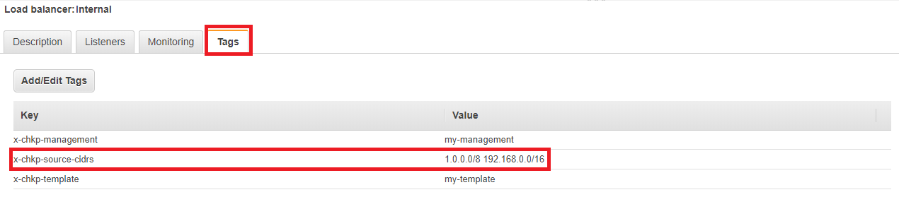
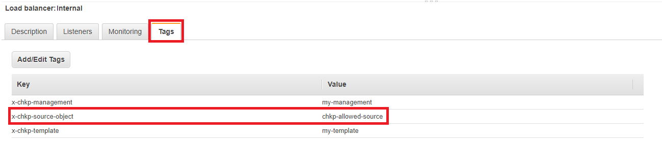
From the Tags tab, add these tags:
-
Tag Key: x-chkp-management
Tag Value: <MANAGEMENT-NAME> -
Tag Key: x-chkp-template
Tag Value: <TEMPLATE-NAME> -
Tag Key: x-chkp-ignore-ports (optional)
Tag Value: <PORTS-LIST>
-
Where:
-
<MANAGEMENT-NAME> - Specifies the name of the Security Management Server. Use the same name you used when you executed the
autoprov_cfg utilityor when you deployed the CloudFormation template. -
<TEMPLATE-NAME> - Specifies the name of the Autoscaling group's template. Use the same name you used when you executed the
autoprov_cfg utilityor when you deployed the CloudFormation template.
|
|
Note:
|