Configuring a High Availability Cluster in GCP
Prerequisites:
-
Google Cloud Platform
 Google® Cloud Platform is a suite of products and services that includes hosting, cloud computing, database services and more. Acronym: GCP. Service Account with the following permissions:
-
Compute Admin
-
Cloud Infrastructure Manager Agent
-
Service Account User
-
Infrastructure Manager Service Agent
-
Service Usage Admin
-
Service Usage Consumer
You can also create the service account during the deployment.

Note - This prerequisite is required only for Marketplace deployments.
-
Step 1: Enable Google Private Access to the Cluster Network
|
|
Note - If the VPC was created during deployment, you can skip this step. |
To enable Google Private Access to the Cluster![]() Two or more Security Gateways that work together in a redundant configuration - High Availability, or Load Sharing. Network:
Two or more Security Gateways that work together in a redundant configuration - High Availability, or Load Sharing. Network:
-
From Cloud Platform, select VPC network > VPC networks.
-
Select cluster-network / cluster network-subnet.
-
Set Private Google access to On.
Step 2: Deploy a Template in GCP
Deploy this solution throughout the GCP![]() See 'Google Cloud Platform'. Portal:
See 'Google Cloud Platform'. Portal:
- Check Point Cloud Firewall High Availability A redundant cluster mode, where only one Cluster Member (Active member) processes all the traffic, while other Cluster Members (Standby members) are ready to be promoted to Active state if the current Active member fails. In the High Availability mode, the Cluster Virtual IP address (that represents the cluster on that network) is associated: (1) With physical MAC Address of Active member (2) With virtual MAC Address. Synonym: Active/Standby. Acronym: HA. BYOL (Bring Your Own License)
OR
- Check Point Cloud Firewall High Availability PAYG (Pay as You Go)
|
Parameter |
Description |
||
|---|---|---|---|
|
Deployment name |
The name of the deployment. Deployment name must contain only lowercase characters, numbers, or dashes. It must start with a lowercase letter and cannot end with a dash. |
||
|
Deployment Service Account |
Select an existing service account with the required permissions (as explained in the prerequisites section) or create a new one. |
||
|
Machines type |
The machine type for both Cluster Members. Machines type determines the specification of your machines including memory, virtual cores, and persistent disk limits. |
||
|
Boot disk type |
The type of disk used for deploying the Cluster Members. |
||
|
Boot disk size in GB |
The size of the disk used for deploying the Cluster Members. |
||
|
OS Version |
The Check Point Cloud Firewall Gateway version to deploy. |
||
|
Deploy HA with public IPs |
Clear this checkbox if you want to deploy the HA with private IP addresses only. |
||
|
The public address of your Security Management Server VPN peers addresses cannot be in this CIDR block, so this value cannot be the zero-address. For the Security Management Servers and Cloud Firewall Gateways compatibility, refer to sk113113. For Management HA/Multi-Domain Security Management Server |
|||
|
The Secure Internal Communication key that creates trusted connections between Check Point components. Trust is required to install policies on Cloud Firewall Gateways and to send logs between Cloud Firewall Gateways and Security Management Servers. |
|||
|
Automatically generate an administrator password |
To manage the environment's security, administrators can connect to the Security Management Server with SmartConsole For additional security, it is recommended to change the password after deployment. |
||
|
Maintenance Mode password hash |
Maintenance mode password hash (relevant only for R81.20 and higher versions). Generate a password hash with the command |
||
|
Allow download from/upload to Check Point |
Do not select this checkbox if you do not want to automatically download Software Blade |
||
|
Admin shell |
Change the admin shell to enable advanced command line configuration. |
||
|
Public SSH key for the user 'admin' |
The public SSH key used to connect to both Cluster Members with the user 'admin'. |
||
|
Enable Stackdriver monitoring |
Select this checkbox to enable Stackdriver Monitoring. |
||
|
Member A Zone |
The zone for deploying Member A. The zone determines available computing resources and where your data is stored and used. See GCP Regions and Zones documentation for more information. |
||
|
Member B Zone |
The zone for deploying Member B. Must be in the same region as Member A's zone. |
||
|
Smart-1 Cloud Token Member A |
The token you generate in Smart-1 Cloud portal. |
||
|
Smart-1 Cloud Token Member B |
The token you generate in Smart-1 Cloud portal. |
||
|
Cluster external subnet CIDR |
The Cluster's Public IP address will be translated to a private address assigned to the Active Provide an RFC 1918 CIDR block in the Cluster external subnet CIDR field, or select a Network and a Subnetwork below the CIDR field. If a range is specified, a new VPC will be created, and the deployment will ignore the selected network above.
|
||
|
Firewall |
These GCP rules will determine if ICMP / TCP / UDP / SCTP / ESP traffic is enabled by default for the provided IP CIDR sources. |
||
|
Management subnet CIDR |
The Public IP address used to manage each member. It is translated to a private address in this external network. Provide an RFC 1918 CIDR block in the Management external subnet CIDR field, or select a Network and a Subnetwork below the CIDR field. If a range is specified, a new VPC will be created, and the deployment will ignore the selected network above. |
||
|
Number of internal networks |
This number will determine how many of the networks specified below this field will be used in this deployment. |
||
|
Internal network(s) |
Provide a RFC 1918 CIDR block in the internal subnet CIDR field, or select a Network and a Subnetwork below the CIDR field. If a range is specified, a new VPC will be created, and the deployment will ignore the selected network above. |
|
|
Notes:
|
Manage the GCP HA with Management High Availability/Multi-Domain Security Management Server High Availability
To manage the GCP HA with Management High Availability![]() Deployment and configuration mode of two Check Point Management Servers, in which they automatically synchronize the management databases with each other. In this mode, one Management Server is Active, and the other is Standby. Acronyms: Management HA, MGMT HA./Multi-Domain Security Management Server High Availability you must set a static route to the Secondary Management IP address on both Cluster Members:
Deployment and configuration mode of two Check Point Management Servers, in which they automatically synchronize the management databases with each other. In this mode, one Management Server is Active, and the other is Standby. Acronyms: Management HA, MGMT HA./Multi-Domain Security Management Server High Availability you must set a static route to the Secondary Management IP address on both Cluster Members:
-
Connect with SSH to each one of the Cluster members.
-
From the Gaia Clish
The name of the default command line shell in Check Point Gaia operating system. This is a restricted shell (role-based administration controls the number of commands available in the shell)., run the command:set static-route <SECONDARY_MANAGEMENT_IP> nexthop gateway address <MANAGEMENT_NETWORK_GATEWAY> on-
SECONDARY_MANAGEMENT_IP- The public address of the secondary Management server using the CIDR notation (IPv4 Address / Mask Length). -
MANAGEMENT_NETWORK_GATEWAY- The Management (nic1) subnet Gateway: In the GCP portal, go to VPC networks, select the Management VPC (nic1) > SUBNETS, and copy the value below Gateway.
-
-
Run:
save config
The deployment takes about five minutes. After the deployment is finished, information is displayed in the deployment details page, such as the Public IP addresses created and the network used for Primary Cluster Synchronization used later in this guide.
Components of the Check Point Solution
- Virtual Private Cloud Networks and subnets:
Cluster
Management
Internal
-
Two Virtual Machines configured as a Check Point cluster.
- Public IP addresses for each Cluster Member Security Gateway that is part of a cluster. in the Cluster VPC:
Primary Public IP address
- Secondary Public IP address
Note - The addresses are not attached to the member's NICs until Step 4: Configure Cluster Objects in SmartConsole.
- Public IP addresses for Security Management Server to each Cluster Member in Management VPC:
Member A IP address
Member B IP address
|
|
Important - No other Virtual Machines can be deployed in the solution's subnet. |
-
Network interfaces can only be configured when instances are created.
-
By default, subnets/CIDR are automatically suggested. If you do not delete it, a new VPC network and a subnet within it, in the same region as the cluster members' Zones, is created.
-
If you want to use existing networks instead of specifying IP CIDR blocks, create them with a subnet in the same region as the cluster members Zones before starting this deployment. When deploying, delete the suggested subnet's address in "Cluster/Management/Internal subnet CIDR", and then select from the subnet CIDR in your existing VPC. If you specify both, then precedence is given to the CIDR field.
-
The Cluster Members each have a network interface in each of the subnetworks specified in this deployment. IP ranges of those subnets must not overlap.
-
The Security Cluster manipulates the routing in the networks you defined as internal in this deployment. The result is that all outbound traffic goes through the Cluster Member that is currently active.
-
It does not deploy any other Virtual Machines in the solution's frontend and backend subnets.
-
Virtual Machines that are launched in the backend subnets, may require Internet access to do final provisioning. Launch these Virtual Machines only after you have applied Hide NAT rules on the cluster object to support this type of connectivity.
-
The Check Point First Time Configuration Wizard automatically deploys after you have set up the cluster object. The cluster object is configured based on the applies parameters.
-
After the First Time Configuration Wizard completes, the Virtual Machines automatically reboot.
-
The member operating mode (A or B) is decided independently of the deployment or the order in which the members were added to the cluster. Instead, it is decided by Private IP addresses of their main network interface.
-
The cluster's secondary address is used for internet access to the member to which it is attached, while it is in standby
State of a Cluster Member that is ready to be promoted to Active state (if the current Active Cluster Member fails). Applies only to ClusterXL High Availability Mode. mode, so that it will be able to receive important updates. The address is not used in the configuration of the cluster. -
The Compute Engine default service account must exist and be enabled in the project.
Step 3 (Optional): Deploy the Cluster without a Public IP address
When you configure High Availability in GCP, you automatically receive Public IP addresses. Do this procedure to remove the Public IP addresses and configure your HA to work with Private IP addresses.
|
|
Note - For new deployments from the GCP Marketplace only, you can clear the Deploy HA with Public IPs checkbox and skip this procedure. |
-
GCP HA deployment.
-
Important: Enable Google private access to the Cluster network.
-
Image build 991001558 and higher.
-
Remove the Public IP addresses:
-
Stop both Cluster members (from the GCP portal) and click Edit.
-
Go to Network interfaces > select the Cluster's external interface > in External IPv4 address select None > Done.
-
Repeat step b. for the Management's interface and save the changes.
-
Go to IP addresses in the GCP portal, search the names of the Public IP addresses, and click on RELEASE STATIC ADDRESS at the top of the page.
For new deployments, search for these Public IP addresses
-
<your-deployment-name>-primary-cluster-address
-
<your-deployment-name>-secondary-cluster-address
-
<your-deployment-name>-member-a-address
-
<your-deployment-name>-member-b-address
-
-
-
Change the Cluster's Public IP addresses in the configuration file $FWDIR/conf/gcp-ha.json on the two Cluster members:
-
Connect with SSH to each Cluster member.
-
Edit the gcp-ha.json file with the command:
# vi $FWDIR/conf/gcp-ha.json -
Change the values of
public_ipandsecondary_public_iptono-public-ip, for example:{
"debug": false,
"public_ip": "no-public-ip",
"secondary_public_ip": "no-public-ip",
"dest_ranges": [
"0.0.0.0/0"
]
}
-
Save the changes in the file and exit the editor.
-
-
If the Security Management Server is in the same VPC as the Cluster members, add these NAT rules:

-
Continue to the next step: Configure Cluster Objects in SmartConsole.
-
For the Cluster's IP address, use member's A Private IP address of the external interface (NIC 0).
-
Each Cluster member uses the Private IP address of the Security Management Server interface (NIC 1).
-
|
|
Notes:
|
Step 4: Configure Cluster Objects in SmartConsole
To configure objects in SmartConsole:
| Step |
Description |
||
|---|---|---|---|
|
|||
|
1 |
Click the Objects menu > New > More > Network Object > Gateways & Servers > Cluster > New Cluster. |
||
|
2 |
Select Wizard Mode. The Check Point Installed Gateway Cluster wizard window opens. |
||
|
3 |
Enter a Cluster Name. Example: |
||
|
4 |
In the Cluster IPv4 Address field, enter the cluster IP address (VIP). You can find the cluster IP address in the GCP portal:
|
||
|
5 |
Click Next. The Gateway Cluster Properties window opens. |
||
|
6 |
Click Add new cluster member.
|
||
|
7 |
Repeat the Step 7 to add the second Cluster Member. |
||
|
8 |
Click Next. The Cluster Topology window opens. |
||
|
9 |
Select the subnetwork provided in the Management network field during the deployment as the Synchronization network. |
||
|
10 |
Configure the other subnetworks as Private use for each member. |
||
|
11 |
Complete the wizard, and then click Publish to save the settings. |
||
|
12 |
Open the Cluster object. |
||
|
13 |
|
||
|
14 |
Click OK |
||
|
15 |
Open the Cluster object. |
||
|
16 |
In the Network management tab, disable Anti-Spoofing for all interfaces by editing those interfaces in the cluster object. |
||
|
17 |
The IPsec VPN |
||
|
18 |
Click OK. |
||
|
19 |
Install the applicable Access Control Policy on the cluster object. |
||
A few minutes after the applicable Access Control Policy is installed, the following changes occur automatically in GCP:
- The following Public IP addresses for each Cluster Member in Cluster VPC will be attached:
Primary Public IP address.
Secondary Public IP address.
- In each of the internal VPC networks, a GCP Route routes all outbound traffic (
0.0.0.0/0) to the Active member with high priority (1) and to the secondary member with lower priority (2).
|
|
Notes:
|
Step 5 (Optional): Configure External and Internal Load Balancers
You can add a Load Balancer to your Cloud Firewall for the GCP environment. After you complete this procedure, the Cloud Firewall Gateways start responding to GCP probes.
|
|
Note - This feature is only available to machines that run Cloud Firewall version R81.10 and higher. |
-
Create an instance group in GCP.
-
In the GCP Portal, search for Instance groups.
-
Click Create instance group > New unmanaged instance group.
-
Select the region where the HA is deployed.
-
Select the Cluster's external network.
-
In VM instances, select both Cluster's members.
-
Click Create.
Note - If each Cluster Member is in a different zone, create one unmanaged instance group for each.
-
-
Create an External Load Balancer in Google Cloud Console.
-
Open the Load Balancing section in Google Cloud Console.
-
Click Create.
-
Select Type > Network Load Balancing. Click Next.
-
Select Passthrough load balancer. Click Next.
-
Select Public facing ("From internet to my VMs").
-
Click Configure.
Backend configuration
-
Enter a name for the new External Load Balancer.
-
Select the region where the Cloud Firewall Gateways High Availability Cluster was deployed.
-
From the Instance group drop-down
State of a Cluster Member during a failure when one of the Critical Devices reports its state as "problem": In ClusterXL, applies to the state of the Security Gateway component; in 3rd-party / OPSEC cluster, applies to the state of the State Synchronization mechanism. A Cluster Member in this state does not process any traffic passing through cluster. list, select the deployed Cloud Firewall Gateways unmanaged instance group. (If you created two unmanaged instance groups, select both by adding another backend). -
In Health check, click Create a new health check:
-
Enter a name for the health check. For example, "
cloudguard-gateways-healthchecks". -
For Port number, enter
8117. (Other ports are not supported.) -
Click Save and continue.
-
-
From Session affinity, select Client IP and protocol.
Frontend configuration
-
Enter a name for the frontend. For example, "
app1-ext-frontend". -
In IP, select a static Public IP address or create a new one.
-
In Port, select the port on which this frontend should listen.
-
Click Review and finalize to review the External Load Balancer configuration.
-
Click Create.
-
-
Create an Internal Load Balancer in Google Cloud Console.
-
Open the Load Balancing section in Google Cloud Console.
-
Click Create.
-
Select Type > Network Load Balancing. Click Next.
-
Select Passthrough load balancer. Click Next.
-
Select Internal ("Only between VMs").
-
Click Configure.
Backend configuration
-
Enter a name for the new Internal Load Balancer.
-
Select the region where the Cloud Firewall Gateways High Availability Cluster was deployed.
-
Choose the internal network the Internal Load Balancer will be facing.
-
From the Instance group drop-down list, select the deployed Cloud Firewall Gateways unmanaged instance group. (If you created two unmanaged instance groups, select both by adding another backend).
-
In Health check, click Create a new health check (if you have already created one for the External Load Balancer, you can use it here as well):
-
Enter a name for the health check. For example, "
cloudguard-gateways-healthchecks". -
For Port number, enter
8117. (Other ports are not supported.) -
Click Save and continue.
-
-
From Session affinity, select Client IP and protocol.
Frontend configuration
-
Enter a name for the frontend. For example, "
app1-int-frontend". -
In IP, select a static internal IP address or create a new one.
-
In Port, select All.
-
Click Review and finalize to review the Internal Load Balancer configuration.
-
Click Create.
-
-
Create Firewall and NAT Rules to allow inbound traffic to the published service or application.
The HA Cluster deployed using the Google Cloud Marketplace template creates a network interface in the external and internal networks. Each Cloud Firewall Gateway in the Cluster has a dynamic object for each network interface. This allows for easier and clearer configuration of Firewall and NAT rules.
A dynamic object is a "logical" object where the IP address is resolved differently for each Cloud Firewall Gateway.
With a dynamic object for each network interface, you can describe Firewall and NAT rules. This dynamic object uses the network interface on which the Cloud Firewall Gateway sends or receives traffic without explicitly stating its IP address.
These dynamic objects are created automatically on each Cloud Firewall Gateway in the Cluster:
Network
Interface
Dynamic Object
External
eth0LocalGatewayExternalInternal
eth1LocalGatewayInternalHow to create dynamic objects
Note - Dynamic objects on the Cloud Firewall Gateway are created automatically.
To create dynamic objects on the Security Management Server, do these steps:
-
In SmartConsole, connect to the Security Management Server (or to the Domain Management Server in the Multi-Domain Security Management Server environment).
-
Create a Dynamic Object
Special object type, whose IP address is not known in advance. The Security Gateway resolves the IP address of this object in real time. named LocalGatewayExternal. For this, in the Object Browser, click New > More > Network Object > Dynamic Object. A Dynamic Object window opens.
Note - Skip this step if the corresponding Dynamic Object already exists.
-
Enter the name of the object. For example,
LocalGatewayExternal. -
Click OK.
-
Repeat Step b for
LocalGatewayInternal.
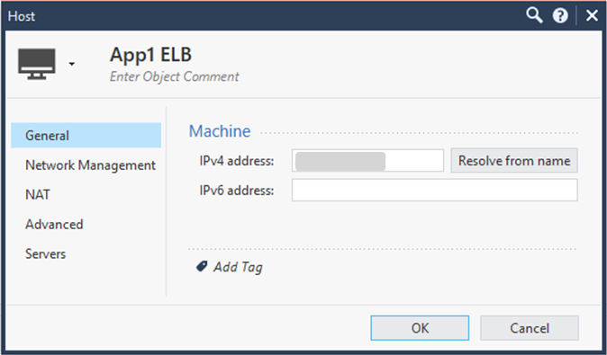
How to create the External Load Balancer Host object
Note - Create a Host object for each Public IP address published on the External Load Balancer.
To create the External Load Balancer Host object, do these steps:
-
In the Object Browser, click New > More > Network Object > Host.
The Host window opens.
-
Enter a descriptive name (for example,
App1-ELB). -
Enter the External Load Balancer's Public IP address.
Example:
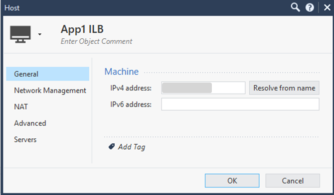
How to create the Internal Load Balancer Host object
Note - Create a Host object for each Internal Load Balancer.
To create the Internal Load Balancer Host object, do these steps:
-
In the Object Browser, click New > More > Network Object > Host. The Host window opens.
-
Enter a descriptive name (for example,
App1-ILB). -
Enter the Internal Load Balancer's Private IP address.
Example:
Notes:
-
GCP TCP Load Balancers forward traffic to the Cloud Firewall Gateways without changing the destination address of the original request. The request's destination address remains the Public IP address of the External Load Balancer.
-
If you have not created an outbound CA certificate, follow the instructions below to create one.

Important - You must have an Outbound CA certificate for an inbound SSL inspection use case.
How to create a Firewall rule
Do these steps:
Step
Description
1
For each GCP forwarding
Process of transferring of an incoming traffic from one Cluster Member to another Cluster Member for processing. There are two types of forwarding the incoming traffic between Cluster Members - Packet forwarding and Chain forwarding. For more information, see "Forwarding Layer in Cluster" and "ARP Forwarding". rule, create a corresponding Firewall rule with these values:Source:
Any(or any other applicable value)Destination
The Public IP address on the External Load Balancer that will accept this traffic.
For example,
App1-ElB.Services:
The service on which the External Load Balancer is listening. For example,
http.Example:
Name
Source
Destination
Services &
Applications
Data
Action
Track
AllowApplAll_InternetApp1-ELBhttp*AnyAcceptLog2
For each Load Balancer rule, create an applicable NAT rule with these values:
Rule
Value
Original Source
All_Internet(do not use "Any")Original Destination
App1-ELBOriginal Services
The service on which the External Load Balancer is listening (HTTP).
Translated Source
LocalGatewayInternal- Right-click on the cell and set the NAT Method toHide.Host
The Host object representing the Internal Load Balancer.
Translated Service
HTTP(or any service representing the port on which the Internal Load Balancer is listening).Example:
Original
SourceOriginal
DestinationOriginal
ServicesTranslated
SourceTranslate
DestinationTranslated
ServiceAll_InternetApp1 ELBhttpH
LocalGatewayInternalS
App1 ILBOriginalHow to set the HTTPS Inspection
Do these steps:
-
In SmartConsole, go to each Cloud Firewall Gateway object and click the HTTPS Inspection tab.
-
Click Server Certificates > Create Certificate.
-
Enter the required information and click OK.
-
Create an HTTPS service similar to the HTTP service from the Create Firewall and NAT Rules to allow inbound traffic to the published service or application. section (select port number 8443).
-
In the Security policy, go to the HTTPS inspection table and add this rule:
-
Source: Any
-
Destination: Any (do not use the Internet object)
-
Service: Select the HTTPS service created in Create an External Load Balancer in Google Cloud Console.
-
Action: Inspect
-
Certificate: The certificate you created in Step b
-
-
Save the changes. Click the diskette icon at the top or press CTRL+S.
-
Publish the changes in SmartConsole.
-
Install the Security Policy
Collection of rules that control network traffic and enforce organization guidelines for data protection and access to resources with packet inspection. on any existing Cloud Firewall Gateway.
-
-
Configure a GCP route.
For the traffic to pass through the Internal Load Balancer, add a route with priority 0 in the internal VPCs in GCP. For example:

-
Configure subnets on the Security Management Server.
-
On the Security Management Server, create a table of subnets that are transferred to the Cloud Firewall Gateways after policy installation.
-
Add this section to the $FWDIR/conf/user.def.FW1 file on the Security Management Server:
Copycloud_balancer_ips = {
<35.191.0.1, 35.191.255.254>,
<130.211.0.1, 130.211.3.254>,
<209.85.152.1, 209.85.155.254>,
<209.85.204.1, 209.85.207.254>
};
Important - For the R82 Security Management Server, add the section above to these files:
-
$FWDIR/conf/user.def.FW1 -
$FWDIR/conf/user.def.R8120CMP
-
-
Install the policy.
-
For more information on Google's Load Balancer, refer to: https://cloud.google.com/load-balancing/docs/network/.
Step 6: Enable Outbound Traffic
To enable outbound traffic:
-
From SmartConsole, connect to the Security Management Server.
-
Find the Security Cluster object in the Gateways & Servers tab.
-
Select the NAT tab.
-
Select the Hide internal networks behind the Gateway's external IP checkbox.
-
Click OK.
-
Install policy.
|
|
Note - NAT does not support connection synchronization during failover. If you configure the cluster to always hide the internal networks (by selecting to automatically add address translation rules - instead of the option described above) this prevents connection synchronization in additional use cases, such as East-West traffic between internal VPCs. |
Step 7: Create Object LocalGatewayExternal in SmartConsole
In SmartConsole, create the Dynamic object called LocalGatewayExternal.
This object represents the Cluster Member's Private IP addresses.
|
|
Note - This Dynamic object step is used in Step 9: Configure VPN. |
Step 8: Configure Inbound Protection (Without Load Balancers)
-
You need to configure Access Control and NAT rules for North-South inbound traffic.
-
You can configure the Cluster's External IP address to listen on the TCP port 443, and forward this traffic to the Active Cluster Member. The Active Cluster Member then inspects the traffic and forward it to the Application server on the TCP port 8084.
-
The Active Cluster Member uses NAT to forward traffic, that belongs to the two web applications, to the appropriate web server.
-
NAT rules are defined with the special Dynamic Object.
-
The Dynamic object
LocalGatewayExternalrepresents the Private IP addresses of the external interface of Member 1 and Member 2. -
For more information, see Step 4: Create Object LocalGatewayExternal in SmartConsole.
|
Step |
Description |
|---|---|
|
1 |
Connect with SmartConsole to your Security Management Server. |
|
2 |
Create a host object to represent:
|
|
3 |
Create a new TCP service. Do the following for each internal port, such as port 8081. Do these steps:
|
Create a NAT rule with these values.
|
NAT Rule |
Value |
|---|---|
|
Rule No |
1 |
|
Original Source |
|
|
Original Destination |
LocalGatewayExternal |
|
Original Services |
The service object that represents the internal port. |
|
Translated Source |
|
|
Translated Destination |
The Host object that represents your web server. |
|
Translated Services |
The service object that represents the port on which the Active member listens (for example, HTTP). |
|
Install On |
|
About this NAT rule:
-
Matches any traffic that arrives at the Cloud Firewall Gateway on the applicable internal port.
-
Translates the destination IP address to the IP address of the Web Servers.
Step 9: Configure VPN
|
Step |
Description |
||
|---|---|---|---|
|
1 |
Create a Network Group object to represent the encryption domain of the cluster:
|
||
|
2 |
Decide if you want to proceed with a default VPN community or use any of your existing VPN Communities. In the first case, just follow the steps below. In the second case, make sure the VPN Community you plan to use is properly configured. For that:
|
||
|
3 |
Enable the VPN Blade and configure your Network Group as the encryption domain of the cluster object:
|
||
|
4 |
Configure the VPN community:
|
||
|
5 |
Configure the outgoing VPN interface:
|
||
|
6 |
Configure the VPN Community to use Permanent Tunnels:
|
||
|
7 |
Install the applicable Access Control Policy on the cluster object. |
Check Point's Remote Access VPN solutions let you create a VPN tunnel between a remote user and the internal network.
Remote Access VPN is supported with GCP HA in the version R81.20 and higher.
For more information, see the R82.10 Remote Access VPN Administration Guide
Step 10: (Optional) Configuring Multiple HA Clusters in the Same VPC
The Shared VPC feature makes sure that when multiple clusters operate within the same internal VPC, the routes created by each deployment have unique names. This prevents route conflicts or overwrites, allowing deployments to coexist safely in shared network environments.
|
|
Important - Version B991001727 or higher is required for this deployment. To verify your version number:
|
|
Step |
Description |
|---|---|
|
1 |
Locate the configuration file on each HA cluster member:
|
|
2 |
Add the
|
|
3 |
Load the new configuration on each HA cluster member. Use this command:
|
|
|
Notes:
|