Using DC Power
To use the DC power connector:
-
Insert the positive and negative wires into the V+ V- and ground (middle) contacts on the DC power connector.
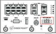
For more information on the features shown in the diagram, see theFront Panel.
-
Tighten the wire-clamps screws securely to prevent the DC wires coming loose.
-
Fasten the 2 side screws of the terminal block connector.

Before wiring the device, make sure that:
-
The DC power connector is suitable for 14 AWG (6A). Torque value is 0.60 Newton/meter (5 Pound/inch).
-
The cross sectional area of the earthing conductors should be at least 14AWG.
-
The temperature rating of the input connection cable should be higher than 95°C.
-
The product supports one power input:
-
3 pin DC power connector, connected the customer’s infrastructure power source, with the following:
-
Nominal: from 12 to 60VDC, -48VDC, as DC Mains
-
Tolerances: -15% for 12VDC, and +20% for 60VDC
-
Maximum Range: from 12 to 72VDC, as DC Source
-
-
-
Based upon the product specification provided by the manufacturer, this unit is intended to be supplied by an UL Listed power supply suitable for use at Tma 75°C, altitude 5000m, and these voltage and current:
-
For V85RWL series: 12VDC-60VDC, -48VDC, 2.3A
-
For V85R series: 12VDC-60VDC, -48VDC, 2.1A
-
For V-81R series 12VDC-60VDC, -48VDC, 2.1A
-
-
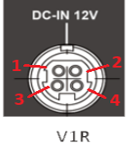
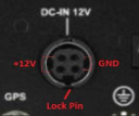
The socket description defines the purpose of each pin:
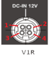

Key
Description
1
+12V
2
Ground (GND)
3
+12V
4
Ground (GND)

Contact Check Point for more information or if you require further assistance.
-48VDC Powering
-
To power the 1575R appliance with -48VDC supply, you need a special power source/supply, such as Delta DPS1800-48/30.
-
Connect the power supply “+” pole to the 1575R “+” pole.
-
Connect the power supply "-" pole to the 1575R “-“ pole.
Power sub-station
To comply with the power sub-station certification (IEEE 1613 and IEC 61850-3), you must connect both power inputs for power redundancy.
To connect DC power to the equipment:
-
Turn OFF all power sources and equipment that will be attached to this appliance.
-
Connect protective earthing first, with at least 14 AWG G/Y color PE conductor, diameter 4.0mm min., screw type PE terminal, and a Spring/Star washer to provide satisfactory locking.
-
Attach signal cables to the appliance.
-
Attach the power cords to the appliance.
For DC systems, make sure the polarity is 12-60VDC, or -48VDC connections.
-
Attach the signal cables to other devices.
-
Connect the power cords to their sources.
-
Turn ON all the power sources.
To disconnect DC power from the equipment:
-
Turn OFF all power sources and equipment that are attached to this appliance.
Disconnect DC power sources at the breaker panel or by turning off the power source. Then remove the DC cables.
-
Remove the signal cables from the connectors.
-
Remove the protective earthing conductor from the devices.
Tolerance
This equipment is intended for power supplied by DC mains.
-
The product supports 10.2VDC~72VDC, but with no power input tolerance.
Make sure the product is connected with a power supply of output voltage lower than 72VDC. A UPS, battery or power regulator is recommended.
-
If the power supply cannot provide stable voltage, we recommend to select lower voltage like 48VDC to prevent damage due to over voltage.
Field Wiring for DC Mains
Only trained service personnel are authorized to install and remove the 12VDC-60VDC Mains or the power adapter AC2DC, and make the connections to and disconnections from the 12VDC-60VDC Mains.
The customer is responsible for ensuring that only trained service personnel install or remove the 12VDC-60VDC power cable.
Safety Statement
|
|
Caution |

To reduce the risk of electric shock or energy hazards:
-
It is the customer's responsibility to supply the necessary power cable.
-
Use a circuit breaker that is rated at 20 amps.
-
Use one of these wires with a minimal temperature rating of 90°C:
-
1.5 mm2 (14 AWG) single copper wire
-
1.5 mm2 (14 AWG) multi-core copper
-
-
Strip the wire, and leave the bare lead approximately 10mm for terminals connection.
-
Apply a torque to the wiring-terminal screws to 0.60 Newton/meter (5 Pound/inch).
-
Wire strip length is 4-4 mm.
-
For supply connections, use wires with a minimal temperature rating of 90°C.
-
If the power source requires ring terminals, you must use a crimping tool to install the ring terminals to the power cord wires.
The ring terminals must be UL approved and must accommodate the wire that is described above.
This equipment is designed to permit the connection the earthed conductor of the DC supply circuit to the earthed conductor at the equipment. If this connection is made, all of the following conditions must be met:
-
This equipment shall be connected directly to the DC supply system earthed electrode conductor or to a bonding jumper from an earthing terminal bar or bus, to which the DC supply system earthed electrode conductor is connected.
-
This equipment shall be located in the same immediate area (such as, adjacent cabinets) as any other equipment that has a connection between the earthed conductor of the same DC supply circuit and the earthed conductor, and also the point of earthed of the DC system. The DC system shall not be earthed elsewhere.
-
The DC supply source shall be located within the same premises as this equipment.
-
Switching or disconnecting devices shall not be in the earthed circuit conductor between the DC source and the point of connection of the earthed electrode conductor.
|
|
Danger |
Electrical current from power, telephone, and communication cables is hazardous and should be handled with caution.
To avoid a shock hazard:
-
Do not connect or disconnect any cables or perform installation, maintenance, or reconfiguration of this product during an electrical storm.
-
Connect all power cords to properly wired sources.
-
Connect to properly wired power sources any equipment that will be attached to this product.
-
When possible, use one hand only to connect or disconnect signal cables.
-
Never turn on any equipment when there is evidence of fire, water, or structural damage.
-
Disconnect the attached DC power sources before you open the device covers, unless you are instructed otherwise in the installation and configuration procedures.
-
Connect and disconnect cables as described when you install, move, or open covers on this product or attached devices.
CAUTION:
Wiring methods used for the connection of the equipment to the DC mains supply are accordance with the National Electrical Code, ANSI/NFPA 70, and the Canadian Electrical Code, Part I, CSA C22.1.
CAUTION:
This equipment has a connection between the earthed conductor of the DC supply circuit and the earthing conductor. See installation instructions.
This equipment has a connection between the earthed conductor of the DC supply circuit and the earthing conductor. All of the following installation conditions must be met:
-
This equipment shall be connected directly to the DC supply system earthing electrode conductor or to a bonding jumper from an earthing terminal bar or bus to which the DC supply system earthing electrode conductor is connected.
-
This equipment shall be located in the same immediate area (such as adjacent cabinets) as any other equipment that has a connection between the earthed conductor of the same DC supply circuit and the earthing conductor, and also the point of earthing of the DC system. The DC system shall not be earthed elsewhere.
-
The DC supply source shall be located within the same premises as this equipment.
-
Switching or disconnecting devices shall not be in the earthed circuit conductor between the DC source and the point of the connection of the earthing electrode conductor.
Installation manual of field wiring for DC Power connected
Attention: This equipment must be installed and removed by trained skilled person in a restricted-access location, as defined by the NEC and IEC 62368-1/IEC 60950-1, The Standard for Safety of Audio/video, information and communication technology equipment.