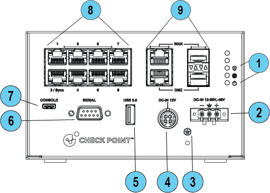
Front Panel
|
Wired |
|
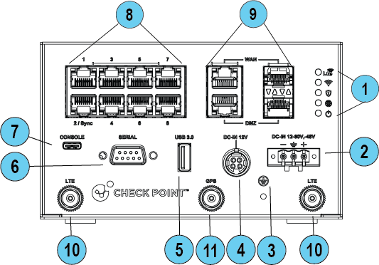
WiFi-LTE |
|
|
|
|
|
|
Note - The Tower LEDs reflect the system status. The 5 LEDs are bi-color (blue and red). |

|
Key |
Item |
Description |
||||||||||
|---|---|---|---|---|---|---|---|---|---|---|---|---|
|
1 |
LEDs |
From top to bottom:
|
||||||||||
|
2 |
12-60V, - 48VDC input |
Connects to the power source cable from your power infrastructure. |
||||||||||
|
3 |
Ground screw |
Protective earthing terminal. |
||||||||||
|
4 |
Power cord socket |
Plug the power adapter cord in here. Use only Check Point power adapters. |
||||||||||
|
5 |
USB port 3.0 (Type-A) |
USB port 3.0 for software download. |
||||||||||
|
6 |
Serial port |
Plug in the serial cable here (standard DB9). |
||||||||||
|
7 |
Console |
Plug in the USB (Type-C) serial console cable here. Baud rate: 115200. |
||||||||||
|
8 |
LAN ports |
LAN ports 1-8. Port #2 is Sync in a cluster. Support 10 / 100 MbE and 1 GbE. |
||||||||||
|
9 |
WAN and DMZ ports |
WAN and DMZ ports support copper RJ45 and fiber interface types. The RJ45 port supports 10 / 100 MbE and 1 GbE. The SFP port supports only 1 GbE.
|
||||||||||
|
10 |
LTE Antennas (WiFi-LTE model only) |
Attach 2 LTE Antennas here:
|
||||||||||
|
11 |
GPS Antenna |
The GPS function is seldom used. You can attach one of the LTE antennas in this position or purchase from a 3rd party vendor. |


|
|
Best Practice -To improve the speed and reliability of the LTE communication link, attach the second LTE antenna (Aux). |

|
|
Notes:
|
Management LED
The Management LED shows the status of the retries mechanism:
|
Action |
Management LED Activity |
|---|---|
|
Zero Touch is running. |
Blinks red (slowly) |
|
Successfully connected to Zero Touch Cloud Server and saved the deployment script. |
Blinks red (rapidly) |
|
Zero Touch process is completed. SMP activation is not needed. |
Off |
|
Activation sleeping time. |
Blinks blue (slowly) |
|
Reactivation. |
Blinks blue (rapidly) |
|
SMP is connected. |
Solid blue |
|
SMP mode is off. |
Off |
|
Gateway failed to connect to the SMP and will exit from the retry script. |
Solid red |
Wait times before retry:
|
Failure |
Waiting Time |
|---|---|
|
1st |
2 minutes |
|
2nd |
4 minutes |
|
3rd |
8 minutes |
|
4th |
16 minutes |
|
Subsequent |
Retries every 16 minutes until Cloud Services are successfully activated |
Network LEDs
The table below describes the network LEDs (RJ45 WAN and LAN ports and the SFP).
Each port uses a bi-color LED to reflect the link/activity and speed.
The SFP port supports only 1GbE.