Connecting DC Power to the 61000 and 41000 Chassis
Connect the DC PEMs in the Chassis to an external battery power source.
You must have a mains DC power supply system that includes batteries and a branch circuit breaker of 125A for each DC PEM.
The DC PEM is described in DC Power Entry Modules (PEMs) for the 61000 and 41000 Chassis.
Required Tools and Parts:
-
4 DC wire leads for each DC PEM that connect to the DC power supply.
Use 6AWG wires. There is no standard for DC wire color coding. Use the color codes on the DC power source (battery) for the DC wire leads.
-
4 barrel lugs (Panduit LCD6-10A-L) for each DC PEM to connect the wire leads to the DC PEM terminal blocks.
-
Crimping tool to connect the wire leads to the lugs.
-
Wire cutter.
-
Wire stripper.
-
Hexagonal-head socket wrench, or nut driver for tightening nuts to terminal studs on each DC PEM.
-
Screwdriver.
Wires and Lugs are not supplied by Check Point
To connect DC power:
Note - These instructions assume that you already installed the DC PEMs in the Chassis.
|
Step |
Instructions |
|---|---|
|
1 |
Set the branch circuit breakers at the mains to the "OFF" position. |
|
2 |
On the both DC PEMs, set all the circuit breakers to the "OFF" position. |
|
3 |
On the first DC PEM, remove the protective plastic cover. Use an appropriate screwdriver. |
|
4 |
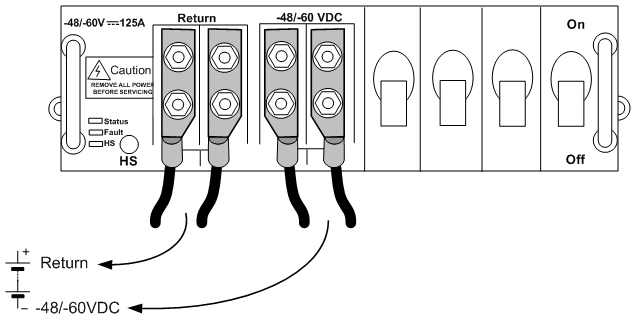
Where the PEM is marked -48/-60 VDC and Return, remove the nuts from the terminal studs. Use a socket wrench or nut driver. |
|
5 |
Connect the -48/-60 VDC cables to the battery:
|
|
6 |
Connect the Return cables to the battery:
|
|
7 |
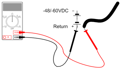
Use a multimeter to make sure the polarity and the range of the DC voltage are correct. Use a multimeter to measure the resistance between the disconnected DC PEM wire leads and the Battery's Return terminal. For all the DC PEM wire leads, one at a time:
|
|
8 |
At the DC PEM:
|
|
9 |
Repeat Steps 3 - 8 for the second DC PEM. |
|
10 |
Set the branch circuit breakers at the mains to the "ON" position. |